Page is loading ...

IB140064EN For more information visit: www.eaton.com
Operation and Maintenance Manual, Automatic Transfer
Switch, Bypass Isolation, Contactor Type, Open/Closed
Transition, ATC-900 Controller, 3000A Frame
Instruction Booklet
Description Page
Introduction . . . . . . . . . . . . . . . . . . . . . . . . . . . . . . . . . . . . 3
Receiving, Handling, and Storage . . . . . . . . . . . . . . . . . . . . . 3
Equipment Description. . . . . . . . . . . . . . . . . . . . . . . . . . . . . 9
Installation and Wiring . . . . . . . . . . . . . . . . . . . . . . . . . . . . .14
Operation of the Bypass Isolation Transfer Switch . . . . . . . . 18
Draw-out, Racking-in, and Removal of Either Contactor . . . . . 24
Testing and Problem Solving . . . . . . . . . . . . . . . . . . . . . . . 25
Maintenance . . . . . . . . . . . . . . . . . . . . . . . . . . . . . . . . . . 27
Renewal Parts Guide . . . . . . . . . . . . . . . . . . . . . . . . . . . . . 29
ATS Quick Start Instructions . . . . . . . . . . . . . . . . . . . . . . . 31

For more information visit: www.eaton.com IB140064EN
Instructional Booklet
Page 2 Effective: April 2018
Operation and Maintenance Manual, Automatic Transfer Switch, Bypass Isolation,
Contactor Type, Open/Closed Transition, ATC-900 Controller, 3000A Frame
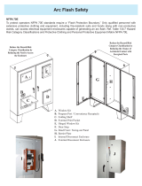
Figure 1. Typical Automatic Transfer Switch Equipment
Nameplate.
Step 1: Remove any dirt or debris that may have collected during
shipment or installation. NEVER use high pressure blow-
ing air. This could drive dirt or other foreign objects into
electrical or mechanical components which could cause
damage. Use an industrial quality vacuum cleaner to
remove any dirt or foreign objects.
Step 2: Be certain all cable connections are correct and that the
phase rotation of both sources match.
Step 3: Inspect the engine start connections and verify the cor-
rect connection of all control wires.
Step 4: Check all programmable setpoints and adjust as neces-
sary. In addition, adjust any optional accessories as
required.
Step 5: Be certain that the actual lug torque values are in keeping
with the requirements outlined in this instruction book to
insure the integrity of power connections.
Step 6: Check to be sure that all covers and barriers are properly
installed and fastened.
ALL POSSIBLE CONTINGENCIES WHICH MAY ARISE DURING INSTAL-
LATION, OPERATION, OR MAINTENANCE, AND ALL DETAILS AND
VARIATIONS OF THIS EQUIPMENT DO NOT PURPORT TO BE COV-
ERED BY THESE INSTRUCTIONS. IF FURTHER INFORMATION IS
DESIRED BY THE PURCHASER REGARDING HIS PARTICULAR INSTAL-
LATION, OPERATION, OR MAINTENANCE OF PARTICULAR EQUIP-
MENT, CONTACT AN EATON REPRESENTATIVE.
WARNING
READ AND UNDERSTAND THE INSTRUCTIONS CONTAINED HEREIN-
AFTER BEFORE ATTEMPTING TO UNPACK, ASSEMBLE, OPERATE,
OR MAINTAIN THIS EQUIPMENT.
WHILE ENERGIZED, AN ARC FLASH AND SHOCK HAZARD EXISTS.
CONSULT NFPA 70E, OSHA AND OTHER APPLICABLE REQUIRE-
MENTS PERTAINING TO OPERATOR SAFETY PRIOR TO SERVICING
EQUIPMENT. ALL WORK ASSOCIATED WITH SUCH ELECTRICAL
EQUIPMENT SHOULD BE PERFORMED ONLY BY A QUALIFIED/COM-
PETENT PERSON AS DEFINED BY APPLICABLE REGULATION WHO
SHOULD ALSO FOLLOW ALL APPLICABLE PROTECTIVE CLOTHING
SYSTEM REQUIREMENTS AND REVIEW APPROPRIATE HAZARD
ASSESSMENT AND ENERGY CONTROL PRECAUTIONS AND PROCE-
DURES. FAILURE TO FOLLOW THIS WARNING COULD LEAD TO
DEATH OR SEVERE INJURY.
TRANSFER SWITCH EQUIPMENT COVERED BY THIS INSTRUCTION
BOOK IS DESIGNED AND TESTED TO OPERATE WITHIN ITS NAME-
PLATE RATINGS. OPERATION OUTSIDE OF THESE RATINGS MAY
CAUSE THE EQUIPMENT TO FAIL RESULTING IN DEATH, SERIOUS
BODILY INJURY, AND/OR PROPERTY DAMAGE. ALL RESPONSIBLE
PERSONNEL SHOULD LOCATE THE DOOR MOUNTED EQUIPMENT
NAMEPLATE AND BE FAMILIAR WITH THE INFORMATION PROVIDED
ON THE NAMEPLATE. A TYPICAL EQUIPMENT NAMEPLATE IS
SHOWN IN FIGURE 1.
E
/1
1of1
Automatic Transfer Switch
Cat No: #"#&%835
GO No: MST0321
Item 1
Poles: 3 Amps:
Volt: 480 VAC
Phase: 3 Hertz: 60 Wire: 4
NOTICE
A FINAL INSPECTION OF THE EQUIPMENT SHOULD BE PERFORMED
PRIOR TO ENERGIZING THE TRANSFER SWITCH.

IB140064EN For more information visit: www.eaton.com
Instructional Booklet
Effective: April 2018 Page 3
Operation and Maintenance Manual, Automatic Transfer Switch, Bypass Isolation,
Contactor Type, Open/Closed Transition, ATC-900 Controller, 3000A Frame
Section 1: Introduction
1.1 Preliminary Comments and Safety Precautions
This technical document is intended to cover most aspects associ-
ated with the installation, application, operation, and maintenance
of ATC-900 controlled contactor based transfer switch equipment
with ratings from usually 1600 through 3000 amperes (A). It is
provided as a guide for authorized and qualified personnel only.
Please refer to the specific WARNING and CAUTION in Section
1.1.2 before proceeding. If further information is required by the
purchaser regarding a particular installation, application, or mainte-
nance activity, contact an Eaton representative See Section 7.4
for Eaton Care number). For information associated with the con-
trol, refer to the separate instruction book for the ATC-900
included in the packet.
1.1.1 Warranty and Liability Information
No warranties, expressed or implied, including warranties of fit-
ness for a particular purpose of merchant-ability, or warranties
arising from course of dealing or usage of trade, are made regard-
ing the information, recommendations and descriptions contained
herein. In no event will Eaton be responsible to the purchaser or
user in contract, in tort (including negligence), strict liability or
otherwise for any special, indirect, incidental or consequential
damage or loss whatsoever, including but not limited to damage or
loss of use of equipment, plant or power system, cost of capital,
loss of power, additional expenses in the use of existing power
facilities, or claims against the purchaser or user by its customers
resulting from the use of the information and descriptions con-
tained herein.
1.1.2 Safety Precautions
All safety codes, safety standards, and/or regulations must be
strictly observed in the installation, operation, and maintenance of
this device.
.
Section 2: Receiving, Handling, and Storage
2.1 Receiving
Every effort is made to ensure that the transfer switch equipment
arrives at its destination undamaged and ready for installation.
Crating and packing is designed to protect internal components as
well as the enclosure. Transfer switch enclosures are skid
mounted and suited for fork lift movement. Care should be exer-
cised, however, to protect the equipment from impact at all times.
Do not remove the protective packaging until the equipment is at
the installation location and ready for installation.
When the transfer switch equipment reaches its destination, the
customer should inspect the shipping container for any obvious
signs of rough handling and/or external damage incurred during
transportation. Record any external and internal damage observed
for reporting to the transportation carrier and Eaton, once a thor-
ough inspection is completed. All claims should be as specific as
possible and include the Shop Order and General Order numbers.
A shipping label which includes a variety of equipment and cus-
tomer information, such as General Order Number (GO #) and Cat-
alog Number (Cat #) is affixed to the top of the shipping container.
Make certain that this information matches other shipping paper
information.
Each transfer switch enclosure is bolted to a rigid wooden pallet.
The pallet is open at two ends for movement by a fork lift. The
shipment is secured and further protected with shrink wrap. Do
not discard the packing material until the equipment is ready for
installation.
A vinyl packet of documents will be found within the enclosure,
usually attached to the inside of the door. Important documents,
such as test reports, wiring diagrams, and appropriate instruction
leaflets, are enclosed within the paclet and should be filed in a
safe place. There may also be keys for the unit depending on the
options.
2.2 Handling
As previously mentioned, the transfer switch equipment is pack-
aged for fork lift movement. Once the equipment is at the installa-
tion location and ready for installation, the packaging material can
be removed. Once the enclosure is unbolted from the wooden pal-
let, it can be installed using the lifting provision located on the top
of the structure. The outside brackets are for shipping purposes
only. Us the internal seismic washers with bolts as shown in Sec-
tion 3. The switch weight is from 2800 lbs to 3100 lbs depending
on the build.
2.3 Storage
Although well packaged, this equipment is not suitable for storage
outdoors. The equipment warranty will not be applicable if there
is evidence of outdoor storage. If the equipment is to be stored
indoors for any period of time, it should be stored with its protec-
tive packaging material in place. Protect the equipment at all
times from excessive moisture, construction dirt, corrosive condi-
tions, and other contaminants.
It is strongly suggested that the package-protected equipment be
stored in a climate controlled environment of -20° to 85°C
(-4° to 185°F) with a relative humidity of 80% or less.
WARNING
THE WARNINGS AND CAUTIONS INCLUDED AS PART OF THE PRO-
CEDURAL STEPS IN THIS DOCUMENT ARE FOR PERSONNEL SAFETY
AND PROTECTION OF EQUIPMENT FROM DAMAGE. AN EXAMPLE
OF A TYPICAL WARNING LABEL HEADING IS SHOWN ABOVE TO
FAMILIARIZE PERSONNEL WITH THE STYLE OF PRESENTATION.
THIS WILL HELP TO INSURE THAT PERSONNEL ARE ALERT TO
WARNINGS, WHICH APPEAR THROUGHOUT THE DOCUMENT. IN
ADDITION, CAUTIONS ARE ALL UPPER CASE AND BOLDFACE.
CAUTION
DO NOT ATTEMPT TO SERVICE OR PERFORM MAINTENANCE ON
EQUIPMENT WHILE IT IS ENERGIZED. FAILURE TO FOLLOW THIS
WARNING COULD LEAD TO DEATH OR SEVERE INJURY. ALWAYS
VERIFY THAT NO VOLTAGE IS PRESENT ON EQUIPMENT PRIOR TO
SERVICING. WHILE ENERGIZED, AN ARC FLASH AND SHOCK HAZ-
ARD EXISTS. CONSULT NFPA 70E AND OSHA GUIDELINES FOR
OPERATOR SAFETY PRIOR TO OPERATING, INSPECTING OR SERVIC-
ING EQUIPMENT.

For more information visit: www.eaton.com IB140064EN
Instructional Booklet
Page 4 Effective: April 2018
Operation and Maintenance Manual, Automatic Transfer Switch, Bypass Isolation,
Contactor Type, Open/Closed Transition, ATC-900 Controller, 3000A Frame
2.4 General Information
Transfer switches are used to protect critical electrical loads
against loss of power. The Source 1 power source of the load is
backed-up by a Source 2 power source. A transfer switch is con-
nected to both the Source 1 and Source 2 power sources and sup-
plies the load with power from one of these two sources. In the
event that power is lost from the Source 1 power source, the
transfer switch transfers the load to the Source 2 power source.
This open transition transfer can be automatic or manual, depend-
ing upon the type of transfer switch equipment being used. Once
Source 1 power is restored, the load is automatically or manually
transferred back to the Source 1 power source, again depending
upon the type of transfer equipment being used.
In addition, the closed transition feature may be applied where it is
desirable to avoid any momentary power interruptions. If both
sources are acceptable as determined by the ATC-900 controller,
a make-before-break transition is performed during a transfer or
retransfer operation.
2.4.1 Transfer Switch
Open/closed transition bypass isolation type automatic transfer
switches consist of four basic elements.
1. Main contacts to connect and disconnect the load to and from
the source of power.
2. Intelligence/supervisory circuits to constantly monitor the con-
dition of the power sources and thus provide the intelligence
necessary for the switch and related circuit operation, includ-
ing safety related logic.
3. Switching devices to effect the transfer of the main contacts
from source to source.
4. Voltage selection, bypass selection, and transformer panel.
The Bypass Isolation Switch shown in Figure 2 is designed for
applications where maintenance, inspection, and testing must be
performed while maintaining continuous power to the load. This
is typically required in critical life support systems and standby
power situations calling for safe system maintenance with no
power disruptions. Such a design allows for the quick removal of
either (patented) switching devices for inspection, maintenance,
or replacement. See Section 3 for more information.
2.4.2 Design Configuration
The Eaton transfer switch is a rugged, compact design utilizing
power contactors to transfer essential loads from one power
source to another. Open transition switching devices are inter-
locked (Mechanically and Electrically) to prevent both switching
devices from being closed at the same time.
The switching devices are in a compact vertical arrangement. The
logic of the switch follows the Product Line's smartEST (smart
Eaton Switch Technology) switch approach. It contains the pat-
ented Dual Automatic Contactor operation. The controller is tied
to both contactors making them both totally automatic. A stan-
dard maintenance switch (MIS) and slider right door make the
switch very safe and easy to maintain and work with. The enclo-
sure is free standing, and is seismic certified.
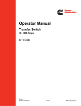
The switching devices have a high withstand/close rating (Table
1). Figure 3 shows the schematic of the Bypass Isolation Switch.
As mentioned, the unit can also be operated as a redundant auto-
matic switch with the controller being full activated with the pri-
mary (ATS) or redundant (Bypass) switch. There is not a need to
move the Bypass contactor to the ATS slot if the ATS contactor is
removed for a dual redundant switch to operate. One contactor
can perform Open or Closed operations.
Table 1. System Coordination Information - UL1008 Withstand Closing Ratings
Tested in accordance with UL1008.
See specific breaker listing for all current breakers listed per UL1008 specification.
Seismic rated at 125%
WARNING
THE CLOSED TRANSITION PRODUCT CONTAINS A SPECIAL CON-
TACT ARRANGEMENT (OVERLAPPING CONTACTS). MISUSE CAN
RESULT IN DEATH, SEVERE PERSONAL INJURY, AND/OR PROPERTY
DAMAGE.
TRANSFER SWITCH
AMPERE RATING
SHORT-CIRCUIT (0.05 SEC)
600V (kA)
SHORT-TIME (0.50 SEC)
600V (kA)
FUSE PROTECTION
FUSE TYPES: L
600V (KA)
UL 1008
1600 100 85 200
2000 100 85 200
2600 100 85 200
3000 100 85 200

IB140064EN For more information visit: www.eaton.com
Instructional Booklet
Effective: April 2018 Page 5
Operation and Maintenance Manual, Automatic Transfer Switch, Bypass Isolation,
Contactor Type, Open/Closed Transition, ATC-900 Controller, 3000A Frame
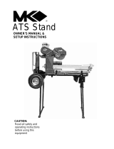
Figure 2. ATS (#1) or Bypass (#2) Shown in Removal Position.
Figure 3. Typical Bypass Isolation Switch, Dual Drawout.
SHOWN AS
NORMAL OPERATION
ATS
SOURCE 1
ATS
SOURCE 2
BYPASS
SOURCE 1
BYPASS
SOURCE 2
LOAD
(4)
(3)
(1)
(2)

For more information visit: www.eaton.com IB140064EN
Instructional Booklet
Page 6 Effective: April 2018
Operation and Maintenance Manual, Automatic Transfer Switch, Bypass Isolation,
Contactor Type, Open/Closed Transition, ATC-900 Controller, 3000A Frame
2.5 Draw-out Switching Devices
All switching devices are 100% rated (including the neutral),
Underwriters Laboratories (UL) 1008 listed, and are built and
tested in an ISO 9002 certified facility to applicable NEMA, ANSI,
IEEE, and UL standards.
There is no difference in the bottom contactor vs the top contac-
tor. The bottom contactor is referred as the ATS (or #1) and the
top contactor is the Bypass (or #2). Figure 4 shows the two con-
tactors in the switch. Either contactor can do all of the transfers
for the loads during the life of the switch. Both contactors are
mounted with mechanical and electrical safety interlocks, in a
"slide" mechanism (Figure 5), allowing the switching device to be
“drawn-out”and isolated for testing or further removed for service,
maintenance, and/or replacement.
Figure 4. Contactor Devices Installed in the Transfer Switch, Both
are Identical.
2.5.2 Draw-out Switching Devices
The ATS draw-out switching device is a design having three posi-
tions with the compartment door closed (RACKED IN, ISOLATED,
RAKED OUT). Figure 5 shows the contactor fully disconnected
from the transfer switch. It is ready for removal. The ATS draw-
out switching device is equipped with both primary and secondary
disconnects to provide for the draw-out functioning. The primary
contacts (Figure 6) are for the high current S1, S2, and load con-
tacts. The secondary contacts are the control and feedback con-
tacts. The secondary connectors are on the top of the contactor
and are somewhat floating for easy racking-in. The operating
mechanism is electrically operated and also has a mechanical man-
ual (paddle) operation if required in an emergency. The user can
choose between three modes of operation, Automatic, Non-Auto-
matic, and Manual. When removed, either switching device can be
inspected, tested, and minor maintenance performed. The inside
of the compartment can also be inspected with the ATS switching
device withdrawn. Although a shutter is standard, caution must
be taken as there is voltage on the run-backs (copper) in the back
of the cell once the contactor is removed.
Figure 5. Draw-out Switching Device Fully Extended for Removal.
BYPASS
ATS
WARNING
DO NOT ATTEMPT TO REMOVE EITHER CONTACTOR WITHOUT A
LIFTING DEVICE AND BEFORE THE SWITCH IS MOUNTED TO THE
FLOOR.
WARNING
EXERCISE CAUTION WHEN PERFORMING MAINTENANCE OR SER-
VICING EQUIPMENT WHILE IT IS ENERGIZED. FAILURE TO FOLLOW
THIS WARNING COULD LEAD TO DEATH OR SEVERE INJURY. WHILE
ENERGIZED, AN ARC FLASH AND SHOCK HAZARD EXISTS. CON-
SULT NFPA 70E AND OSHA GUIDELINES FOR OPERATOR SAFETY
PRIOR TO SERVICING OR OPERATING EQUIPMENT.

IB140064EN For more information visit: www.eaton.com
Instructional Booklet
Effective: April 2018 Page 7
Operation and Maintenance Manual, Automatic Transfer Switch, Bypass Isolation,
Contactor Type, Open/Closed Transition, ATC-900 Controller, 3000A Frame
Figure 6. Four Pole Primary Connections on the ATS Switching
Device, Secondary Connections (Not Shown) on Top.
2.6 Transfer Switch Catalog Number Identification
Transfer switch equipment catalog numbers provide a significant
amount of relevant information that pertains to a particular piece
of equipment. The catalog number identification table (Table 2)
provides the required interpretation information. An example for
an open transition switch is offered to initially simplify the pro-
cess.
Example: Catalog Number (circled numbers correspond to position
headings in Table 2).
The catalog number BIC9F5E30400XSU describes a dual drawout
bypass isolation transfer switch with the switching devices
mounted vertically in the enclosure. The intelligence, represented
by the ATC-900 is a microprocessor-based logic package. The
contactor is used as the switching device and it is a 3 position
type. The continuous current rating of this equipment is 3000A
and is applicable up to 600 Vac, 60 Hz. The transfer switch equip-
ment is enclosed in a NEMA 1 enclosure and is listed for Under-
writers Laboratories (UL) and Canadian Standards Association
(CSA) applications. It is also Seismic qualified.
Table 2. Transfer Switch Catalog Number Explanation.
Secondary Contacts
BI C & % 300 X S U
1to2 3 4 5 6 7 8 9to
12 13 14 15
to
BI
3000
Orientation
C= Contactor
Amperes
2000=2000A
2600=2600A
3000=3000A
Voltage
A=120V, 60Hz
B=208V, 60Hz
E=600V, 60Hz
G=220V, 50Hz
H=380V, 50Hz
K=600V, 50Hz
M=230V, 50Hz
N=401V, 50Hz
O=415V, 50Hz
W=240V, 60Hz
X=480V, 60Hz
Z=365V, 50Hz
Number
of Poles
2=2 pole
3=3 pole
4= 4 pole
Enclosure
S=NEMA 1
R=NEMA 3R
Logic
9=ATC-900
Certification
U=UL Listed
R=UL Recognized
Type
BI=Bypass
Isolation
Open
Transition
C 9
F5
X
3 X
S
U
Mechanism
CB=Bypass
Isolation
Closed
Transition
F5=F type, inphase/
delayed transition
E=Draw-out
Switch
G5=G type, inphase/
delayed transition
1600=1600A

For more information visit: www.eaton.com IB140064EN
Instructional Booklet
Page 8 Effective: April 2018
Operation and Maintenance Manual, Automatic Transfer Switch, Bypass Isolation,
Contactor Type, Open/Closed Transition, ATC-900 Controller, 3000A Frame
2.7 Environmental Conditions
2.7.1 Operational Conditions
Normally, an ATS is applied indoors in an electrical equipment
room. The ambient temperature range for operation is between -
20 and 60°C (-4 to 140°F), no greater than 90% humidity (non-
condensing). A heater option may be required for general heating
or condensation.
2.8 Glossary
With respect to their use within this document and as they relate
to transfer switch and controller operation, the following terminol-
ogy is defined. Other specific terms can be found in the
ATC-900's instruction booklet.
Automatic Operation
The transfer switch is controlled by the ATC-900 and is self acting
in either Open or Closed Transition.
Available
A source is defined as “available” when it is within its undervolt-
age/overvoltage/ underfrequency/overfrequency (if applicable) set-
point ranges for the nominal voltage and frequency setting.
Bypass
To transfer to another switching device, same source, with no
power interruption.
Connected
Connected is defined as when the load is connected to either the
preferred or alternate source.
Failed or Fails
A source is defined as “failed” when it is outside of the applicable
voltage and frequency setpoint ranges for the nominal voltage and
frequency setting for a time exceeding 0.5 seconds after the time
delay emergency fail (TDEF) time delays expires.
Failsafe
Failsafe is a feature that prevents disconnection from the only
available power source and also forces a transfer or re-transfer
operation to the only available power source.
Re-Transfer
Re-transfer is defined as a change of the load connection from the
alternate source to the preferred source.
Manual Operation
A transfer between power sources is accomplished using the man-
ual controls located on the face of the switching device.
Monitor Mode
Provides an input to disable automatic control in the ATC-900
controller. The controller continues to accurately monitor source
status and set points can be changed, however no action will be
initiated by the controller.
Non-Automatic Operation
The transfer switch is not self acting and the user may transfer
the load to Source 1, open, or source 2 electrically. The user could
remove power to the load if the source switched to is not pow-
ered.
Source 1
Source 1 is the primary source (normal source, normal power
source, or normal).
Source 2
Source 2 is the secondary source (emergency source, emergency
power source, emergency, standby, or backup source).
Source 1: Failed or Fails
Source 1 is defined as “failed” when it is outside of its undervolt-
age/overvoltage/ underfrequency/overfrequency (if applicable) set-
point ranges for the nominal voltage and frequency setting.
Source 2: Failed or Fails
Source 2 is defined as “failed” when it is outside of its undervolt-
age/overvoltage/ underfrequency/overfrequency (if applicable) set-
point ranges for the nominal voltage and frequency setting for a
time exceeding 0.5 seconds after the Time Delay Emergency Fail
(TDEF) time delay expires.
Transfer
Transfer is defined as a change of the load connection from the
preferred source to the alternate source.
Trip (Open)
Device is not connected to Source 1/ or Source 2.
The main contacts are open, in the "neutral" position.

IB140064EN For more information visit: www.eaton.com
Instructional Booklet
Effective: April 2018 Page 9
Operation and Maintenance Manual, Automatic Transfer Switch, Bypass Isolation,
Contactor Type, Open/Closed Transition, ATC-900 Controller, 3000A Frame
Section 3: Equipment Description
3.1 General
The ATS consists of of these main LRUs (Line Replaceable Units):
1. The contactor switching devices;
2. The voltage selection at the transformer PT panel;
3. The Logic Control (ATC-900);
4. The Logic Controller;
5. The Slider door including the components and customer cus-
tom order components.
The transfer switch shown in Figure 7 is depicted with both con-
tactor doors open and the Maintenance slider door also opened.
The slider door has all the components including any custom order
engineered (COE) items. The COE components are usually near
the bottom of the door. The transformer assembly is very accessi-
ble and is on the shelf at the bottom of the slider door. There is an
Maintenance (MIS) switch that turns off power to the slider door
(see Section 5.4).
The customer connections such as “Engine Start” and user I/Os
are on the slider door and are very convenient for the user.
Figure 7. The Bypass Isolation Switch.
ATC-Controller
ATS Secondary Terminal Blocks
Logic Controller
Contactor
Front Access Panel
Slider Door
Maintenance Isolation Switch (MIS)
Main Terminal Blocks
Option Panel
Transformer Assy
(CPT)
ATS (#1)
Bypass (#2)
Bypass Secondary Terminal Blocks
Switching
Devices

For more information visit: www.eaton.com IB140064EN
Instructional Booklet
Page 10 Effective: April 2018
Operation and Maintenance Manual, Automatic Transfer Switch, Bypass Isolation,
Contactor Type, Open/Closed Transition, ATC-900 Controller, 3000A Frame
3.2 Switching Device (Contactor)
The switching device consists of a means for making load, power,
and neutral connections. The main contacts and the switching
mechanism are all on one steel frame (see Figure 8). The actual
power connections fingers are shown in Figure 9.
Figure 8. Front View of Switching Device.
Figure 9. Rear View of Switching Device.
3.2.1 Main Contacts
The main contacts connect and disconnect the load to and from
the different power sources. The main contacts for the Source 1,
Source 2, and Load power sources are continuous duty devices
that are rated for all classes of loads. In addition, they have high
dielectric strength, heavy-duty switching and withstand/closing
capabilities. As shown in Figure 9, the top row are the S1 connec-
tions, the middle row are the Load connections, and the bottom
row are the S2 connections.
3.2.2 Switch Device Interlocks (Mechanical and Electrical)
The transfer switch has electrical and mechanical interlocks to
prevent the two sets of main contacts from being closed simulta-
neously (Source 1 to Source 2) except in the closed transition
mode. If not a closed transition type, there are mechanical inter-
locks inside the contactor to prevent the contactor from closing
on S1 and S2 at the same time. (Closed transition is performed on
the same contactor, ATS or Bypass). There are electrical inter-
locks to remove both sources on a single contactor if it is over
100 msec as the closed transition's open is less than 100 msec
by specification.
There are also mechanical and electrical interlocks that go
between each contactor to prevent the closures of the different
sources. A synapse of the interlocks are described below:
Closed Transition Interlocks:
ATS S1 & S2 Electrical Interlock
Bypass S1 & S2 Electrical Interlock
ATS & Bypass S1 & S2 Electrical & Mechanical Interlocks
Open Transition Interlocks:
ATS S1 & S2 Electrical & Mechanical Interlocks
Bypass S1 & S2 Electrical & Mechanical Interlocks
ATS & Bypass S1 & S2 Electrical & Mechanical Interlocks
Figure 10 shows the mechanical interlocks between the two con-
tactors (ATS and Bypass Switch). When the operation is per-
formed to go from the ATS to the Bypass or the Bypass to the
ATS, the same source is closed for about a second. This is nor-
mal since both contactors are available for Automatic (patented)
operation. There is also an electrical Interlock in case a manual
close using the paddle is used.

IB140064EN For more information visit: www.eaton.com
Instructional Booklet
Effective: April 2018 Page 11
Operation and Maintenance Manual, Automatic Transfer Switch, Bypass Isolation,
Contactor Type, Open/Closed Transition, ATC-900 Controller, 3000A Frame
Figure 10. External Contactor Mechanical Interlock.
3.2.3 Draw-out Interlocks
The transfer switch has several safety interlocks in the draw-out
mechanism to ensure that the switching device is always in the
“neutral” position when connecting or disconnecting it from the
line and load stabs.
The switching device will close on an available source Automati-
cally (ATS or Bypass) only with the door(s) closed and latched.
For example; when a contactor (either one) is isolated or removed
and the other contactor is in the automatic mode will automati-
cally switch if a power source becomes available. In this case, the
contactor that is loaded will require the door to be closed in order
for it to operate in the automatic or non-automatic mode. If the
automatic operation is not desired, turn the top switch to Non-
Auto and the controller will then be placed in Monitor Mode.
Please see Section 5, Operation, for more information and usage
maps.
3.2.4 Switching Devices
The transfer switch uses contactor switching devices. A colored
indicator flag on the contactor shows whether it is in the OFF
(OPEN) or ON (CLOSED) position (see Figure 8). These are not vis-
ible when the doors are closed and latched. The controller is used
to show the user the position of each contactor when the door is
closed.
The contactor switching device is electrically closed by momentar-
ily (milliseconds) energizing a spring release. The spring is always
charged when power is on and takes about 3 seconds to charge.
3.2.5 Draw-out Mechanism
The draw-out mechanism is described in detail in Section 6. The
draw-out mechanism is designed to operate with the door closed
and latched for additional safety. Figure 11 shows the unit being
racked-in or out, with a 1/2" socket, from the power runbacks
with the door closed and latched. Figure 12 shows the switching
device drawn out with the slider door open. A lifting device is
required to remove a contactor.
Figure 11. Racked in or Draw-out Mechanism.
Figure 12. Draw-out Switching Device Fully Extended (Removed)
from the Transfer Switch's Runbacks. ATS or Bypass.
WARNING
EXERCISE CAUTION WHEN PERFORMING MAINTENANCE OR SER-
VICE EQUIPMENT WHILE IT IS ENERGIZED. FAILURE TO FOLLOW
THIS WARNING COULD LEAD TO DEATH OR SEVERE INJURY. USE
THE MIS SWITCH. WHILE ENERGIZED, AN ARC FLASH AND SHOCK
HAZARD EXISTS. CONSULT NFPA 70E AND OSHA GUIDELINES FOR
OPERATOR SAFETY PRIOR TO SERVICING OR OPERATING EQUIP-
MENT.
WARNING
DO NOT ATTEMPT WITH DOOR OPEN.

For more information visit: www.eaton.com IB140064EN
Instructional Booklet
Page 12 Effective: April 2018
Operation and Maintenance Manual, Automatic Transfer Switch, Bypass Isolation,
Contactor Type, Open/Closed Transition, ATC-900 Controller, 3000A Frame
3.3 Line Voltage Selection Panel
The voltage selection panel consists of multi-tap transformers,
contained in a steel case mounted in the bottom of the control
compartment (Figure 13). The cover has two connectors on it,
with the one being selectable depending on the voltage applied to
S1 and S2. The transformer unit is easily removed by removing
the two front screws and disconnecting the two plugs. The rear
of the transformer enclosure has two flanges that are inserted into
two slots. The voltage is selected by simply removing the plug
from the default selected voltage on the cover plate and installing
the plug to the desired available voltage. Ensure that the plug is
inserted into the intended voltage at start-up. There is a similar
selection panel for international voltages. Depending on the
options of the switch, some may only have a single tap on the
transformer.
Figure 13. Transformer Voltage Selection Terminals.
3.4 ATC-900 Controller
The Controller panel provides the intelligence and supervisory cir-
cuits which constantly monitor the condition of both the Source 1
and Source 2 power sources, thus providing the required intelli-
gence for transfer operations. Detailed information for controller
operation is presented in separate documents:
• ATC-900 Instruction Book (IB140012EN - Open or Closed Tran-
sition.
• There is an additional Logic Controller (LC) for controlling the
interlocks, the ATS contactor removal/insertion logic, and the
bypass functions. It is located on the slider door and is a white
metal box. The unit is made to be a Line Replaceable Unit
(LRU).
• For current metering, there is a DCT module available that
attaches on to the back of the ATC-900, see Figure 23 The
DCT also serves as a 24VDC input for backup power to the
controller. See the ATC-900 instruction booklet for more infor-
mation. The DCT module could be used with the buffer to keep
the controller powered for about 20 seconds (to keep communi-
cations active); which is more than enough to ride through a
power outage.
• I/O Modules are available that will increase inputs and outputs
(4 in and 4 out per module) if additional I/Os are required. See
the ATC-900 instruction booklet for more information.
3.5 Neutrals
All 2-pole and 3-pole transfer switches are equipped with 100%
rated neutral connections. Figure 14 shows the interconnect 4-
pole bus configuration for the Switch. Figure 15 shows the ground
bar. The bus is also marked with S1, S2, and neutral. The 3-pole
would have a separate neutral in the rear bus copper area.
Figure 14. 4 Pole Rear Copper Bus, no Lugs Shown.
Ground Bar
LOAD
S1
S2

IB140064EN For more information visit: www.eaton.com
Instructional Booklet
Effective: April 2018 Page 13
Operation and Maintenance Manual, Automatic Transfer Switch, Bypass Isolation,
Contactor Type, Open/Closed Transition, ATC-900 Controller, 3000A Frame
Figure 15. Ground Bar.
3.6 Features/Options
3.6.1 Some Popular Features for the Automatic Transfer Switch
A variety of standard and optional features are available for Eaton
ATSs. All features or combinations of features may not be avail-
able on specific ATSs. All features and/or accessories are Under-
writers Laboratories (UL) listed unless noted. The primary function
of the controller is to accurately monitor power sources and pro-
vide the necessary intelligence to operate a transfer switch in an
appropriate and timely manner. In addition, the controllers pro-
vides useful present and historical data, reliable two-way commu-
nications, and programming through the device’s faceplate or
communications option.
3.6.1.1 Standard Features
There are a several standard features of the ATC-900 Controller.
All features are activated to the user except three items: 1) closed
transition, 2) I/O Module(s), and the DCT module. Please see the
specific controller Instruction booklet for the many standard fea-
tures available. A variety of programmable features are available
to meet a wide variety of application requirements. Individual fea-
tures or feature combinations provide the intelligence required to
tailor switches to individual needs. The specific variable setpoints
associated with standard and factory activated features are stored
in a nonvolatile memory and feature setpoints are available for
customer adjustments. The USB can be used to download/upload
setpoints, and download events.
3.7 Enclosure
The rugged steel switch enclosure is supplied with hinges to
insure proper support of the doors and door mounted devices.
The hinges have removable hinge pins to facilitate door removal
and all doors contain connectors for easy electrical reconnect. The
doors are supplied as standard with padlock latches. Cable entry
holes are the customer’s responsibility. The right-side slider door
is used to mount a variety of lights, switches, and push buttons,
depending upon the options required for a particular switch. The
switch enclosures and some internal steel mounting plates, such
as the transformer panel mounting plate, go through a pre-treat-
ment cleaning system prior to painting to insure a durable finish.
Should the enclosure become scratched and in need of touch up
paint, use ANSI 61. All remaining steel is galvanized. The standard
switch enclosure is NEMA Type 1 for general indoor use.
There are many other options for these switches such as meter-
ing, Remote Annunciator Control (RAC), ATS-Monitor, Gateways,
and Surge devices. Please consult factory for more features and
options.
3.8 Standards
Eaton transfer switch equipment is listed for application by UL and
CSA. In addition, Eaton Automatic Transfer Switches are listed
under Standard UL 1008. This standard covers requirements for
Automatic Transfer Switches intended for use in ordinary loca-
tions to provide for lighting and power as follows:
a. In emergency systems, in accordance with articles 517 and
700 in the National Electrical Code (NEC), American National
Standards Institute/National Fire Protection Association
(ANSI/NFPA) 70 and the NFPA No. 76A and/or
b. In stand-by systems, in accordance with article 702 of the
NEC and/or
c. In legally required stand-by systems in accordance with article
701 of the NEC.
d. In Critical Operations Power Systems (COPS) per article 708 of
the NEC.
Eaton Automatic Transfer Switches are available to meet NFPA
110 for emergency and stand-by power systems, and NFPA 99
for health care facilities when ordered with the appropriate
options.
3.9 Power Off Buffer
For faster switching times when power is removed from the
switch, there is a non-maintenance buffer added that keeps power
onto the Logic Controller, not the ATC, for about 30 seconds.
The additional time that the Logic Controller unit is powered pre-
vents it from having to reset when the normal source fails. It is a
small device and and is located on the slider door panel.
The buffer is din-rail mounted and is factory set (22-24Volts) with
no maintenance required. The green LED on the Buffer will flash
when the unit is being discharge or charged, otherwise it will
remain on. Since this transfer switch has a buffer, the DCT mod-
ule could be used with the buffer to keep the controller powered
for about 20 seconds (to keep communications active); which is
more than enough time to ride through a power outage.
Ground

For more information visit: www.eaton.com IB140064EN
Instructional Booklet
Page 14 Effective: April 2018
Operation and Maintenance Manual, Automatic Transfer Switch, Bypass Isolation,
Contactor Type, Open/Closed Transition, ATC-900 Controller, 3000A Frame
Section 4: Installation and Wiring
4.1 General
Eaton transfer switches are factory wired and automatically tested
with a test report included. Installation requires solidly mounting
the enclosed unit and connecting the power cables and auxiliary
pilot circuits. Physical mounting procedures and power cable con-
nections are covered in this section. All other required wiring or
electrical connection references are covered in a separate Cus-
tomer Wiring Diagram packaged with the transfer switch.
Locate the wiring booklet, review it, and keep it readily available
for reference purposes during installation and testing. Once a
transfer switch is properly installed and wired, it should be
mechanically and electrically checked for proper installation and
operation. The procedures for these initial mechanical and electri-
cal checks are outlined in Section 7 of this instruction manual.
4.2 Mounting Location
Choose a location that offers a flat, rigid mounting surface capa-
ble of supporting the weight of the enclosed transfer switch
equipment. Avoid locations that are moist, hot, or dusty. How-
ever, Eaton offers enclosure designs that can be used in special
environments. If there are any doubts as to the suitability of the
location, discuss it with your Eaton representative.
Check to make certain that there are no pipes, wires, or other haz-
ards in the immediate area that could create a problem. The pan-
els provide ample room for rear cable entry from top, bottom, and
sides. At no time should cable be routed to retard the action of
relays or cover the logic in a way that restricts adjustments.
Maintain proper electrical clearances between live metal parts and
grounded metal.
4.3 Unpackaging and Inspection
Proceed with the following four steps.
Step 1: Carefully uncrate the transfer switch. If damage is visible,
please contact your local Eaton sales representative or the
factory.
Step 2: Visually verify that there are no broken or damaged com-
ponents or evidence of distorted metal or loose wires as a
result of rough handling.
Step 3: A label on the door provides specifications for your trans-
fer switch. Verify that these specifications comply with
your requirements.
Step 4: Remove any braces or packing used to protect the trans-
fer switch or internal components during shipping. The
switch has 12 bolts holding the unit down into the pallet
each with a seismic washer. Do not throw away the seis-
mic washers as they will be used when mounting the
switch on the pad.
4.4 Mounting Procedure
With the enclosed transfer switch equipment unpacked and ready
for mounting, proceed with the following steps.
Step 1: Mounting and cabling access is best provided by remov-
ing side and rear covers (when applicable). If required to
remove the enclosure covers a 3/8 socket will be
required. The back and two sides are similar in that if the
lower panels need to be removed, the top panel must be
removed first.
Step 2: Gently maneuver the switch into its location using all of
the supplied lift brackets.
Step 3: Bolt the enclosure to the base (see Figures 16 & 17). Seis-
mic mechanical mounting requirements use 12 5/8-11
UNC grade 5 or better hex head bolts with the included
washers (Eaton pn. 66A8231H14). Also see the outline
drawing for locations.
Step 4: Tighten bolts to 120 ft-lbs (163 N
m).
Figure 16. Mounting With Seismic Washer.
CAUTION
SINCE THE ENCLOSED TRANSFER SWITCH MUST BE LIFTED INTO
PLACE FOR MOUNTING, BE CERTAIN THAT ADEQUATE RESOURCES
ARE AVAILABLE FOR LISTING TO AVOID PERSONNEL INJURIES OR
EQUIPMENT DAMAGE.
CAUTION
EXTREME CARE SHOULD BE TAKEN TO PROTECT THE TRANSFER
SWITCH FROM DRILL CHIPS, FILLINGS, AND OTHER CONTAMI-
NANTS WHEN MAKING THE CABLE ENTRY HOLES AND MOUNTING
THE ENCLOSURE TO PREVENT COMPONENT DAMAGE OR A
FUTURE MALFUNCTION.
NOTICE
CABLE ENTRY HOLES ARE NOT PART OF THE ENCLOSURE WHEN
SHIPPED FROM THE FACTORY AND MUST BE PROVIDED IN THE
FIELD, EITHER BEFORE OR AFTER MOUNTING THE ENCLOSURE.

IB140064EN For more information visit: www.eaton.com
Instructional Booklet
Effective: April 2018 Page 15
Operation and Maintenance Manual, Automatic Transfer Switch, Bypass Isolation,
Contactor Type, Open/Closed Transition, ATC-900 Controller, 3000A Frame
Figure 17. Mounting using 12 Seismic Washers.
4.5 Power Cable Connections
The standard outline for the switch is shown in Figure 18. The
normal outline dimensions are 44.00 w x 90 h x 60 d.
Figure 20
shows the connections for the Switch. The bus is labeled inside
the unit as shown in Figure 19. The Ground bar is also shown. The
4-pole would have the neutral on the rear bus copper as shown
and a 3-pole would have a separate neutral. All will be 100%
rated.
Figure 18. Enclosure Outline.
WASHER
SEISMIC
WASHER
60
89.74
44.00
90
20.61
47.03
CG

For more information visit: www.eaton.com IB140064EN
Instructional Booklet
Page 16 Effective: April 2018
Operation and Maintenance Manual, Automatic Transfer Switch, Bypass Isolation,
Contactor Type, Open/Closed Transition, ATC-900 Controller, 3000A Frame
Figure 19. 4 Pole Bus & Ground Bar Shown.
Proceed with the following steps:
Step 1: Verify that the line and load cables comply with applica-
ble electrical codes.
Step 2: Verify that the transfer switch rated current and voltage
(see identification plate on the door of the transfer
switch) agree with system current and voltage.
Step 3: After the transfer switch is mounted, provide the conduit
or cable openings as required. Ensure that no metal filings
contaminate the transfer switch components.
Step 4: Test all power cables before connecting them to the unit
to insure that the conductors or the cable insulation have
not been damaged while being pulled into position.
Step 5: Carefully strip the insulation from the power cables.
Avoid nicking or ringing of the conductor strands. Pre-
pare the stripped conductor termination end by cleaning
it with a wire brush.
Step 6: Make the necessary connections of any options using the
wiring diagrams supplied with the unit.
Power cables are to be connected to solderless screw type lugs
located on the transfer switch switching devices. Refer to the
separate Customer Wiring Diagrams supplied with the transfer
switch equipment for power termination. Verify that the lugs sup-
plied will accommodate the power cables being used. Also verify
that the cables comply with local electrical codes. Standard trans-
fer switch equipment, as supplied from the factory, will accommo-
date the wire sizes shown in Table 3. Compression lugs are
available as an option.
Power sources, load conductors, and control wiring should be
connected to locations as indicated in the customer wiring dia-
gram supplied with the ATS equipment.
Table 3. Wire Size for Available Power Cable
Connections.
.
Once the ATS equipment has been installed and wired, perform
the initial mechanical and electrical procedures as outlined in Sec-
tion 6 to verify that the equipment is installed and operating prop-
erly.
DANGER
POWER CONDUCTORS MAY HAVE VOLTAGE PRESENT THAT CAN
CAUSE SEVERE PERSONAL INJURY OR DEATH. DE-ENERGIZE ALL
POWER AND CONTROL CIRCUIT CONDUCTORS (FIGURE 19) TO BE
CONNECTED TO THE TRANSFER SWITCH EQUIPMENT BEFORE INITI-
ATING WORK WITH THE CONDUCTORS AND/OR TERMINATING
THEM TO THE EQUIPMENT. ALWAYS VERIFY THAT NO VOLATGE IS
PRESENT ON THE EQUIPMENT PRIOR TO SERVICING. CONSULT
NFPA 70E AND OSHA GUIDELINES FOR OPERATOR SAFETY PRIOR
TO SERVICING EQUIPMENT.
CAUTION
USE OF CABLE LUGS NOT DESIGNED FOR THE TRANSFER SWITCH
APPLICATIONS MAY CAUSE HEATING PROBLEMS.
CAUTION
TO HELP PREVENT COMPONENT DAMAGE OR FUTURE MALFUNC-
TIONS, USE EXTREME CARE TO KEEP CONTAMINANTS OUT OF THE
TRANSFER SWITCH EQUIPMENT WHEN MAKING POWER CABLE
CONNECTIONS.
Ground Bar
LOAD
S1
S2
AMPS MAX # OF
CONDUCTORS
TERMINAL SIZE TORQUE FT-LB (NM)
1600- 8 1/0-750 CU/AL 32 (42)
2600-3000 12 1/0-750 CU/AL 32 (42)
WARNING
POWER CONDUCTORS AND CONTROL WIRING MAY HAVE VOLT-
AGE PRESENT THAT CAN CAUSE SEVERE PERSONAL INJURY OR
DEATH. DEENERGIZE ALL POWER AND CONTROL CIRCUIT CON-
DUCTORS BEFORE BEGINNING TO PERFORM ANY WIRING ACTIVITY
TO OR WITHIN THE ATS EQUIPMENT. ALWAYS VERIFY THAT NO
VOLTAGE IS PRESENT ON EQUIPMENT PRIOR TO SERVICING.
WHILE ENERGIZED, AN ARC FLASH AND SHOKC HAZARD EXISTS.
CONSULT NFPA 70E AND OSHA GUIDELINES FOR OPERATOR
SAFETY PRIOR TO SERVICING, INSPECTING OR OPERATING EQUIP-
MENT.
CAUTION
ENSURE THE ATS VOLTAGE IS SET CORRECTLY ON THE TRANS-
FORMER PANEL. IT SHOULD BE THE SAME AS THE SOURCE 1 AND
SOURCE 2 LINE VOLTAGES. OPERATING THE EQUIPMENT ON
IMPROPER VOLTAGE CAN CAUSE EQUIPMENT DAMAGE.

IB140064EN For more information visit: www.eaton.com
Instructional Booklet
Effective: April 2018 Page 17
Operation and Maintenance Manual, Automatic Transfer Switch, Bypass Isolation,
Contactor Type, Open/Closed Transition, ATC-900 Controller, 3000A Frame
.
4.5.1 Customer Interface Terminal Blocks
There are terminal blocks inside the control compartment on the
slider door for customer interface shown in Figure 20 and the
table below. Refer to the switch drawings for locations and func-
tions of the terminal blocks. The auxiliary form C position terminal
blocks are located on the top of each contactor (Figure 21) and
contain a total of 6 user form C type on source 1 and 8 user form
C type on source 2 (no powered required) contacts. Sheet S002
of the transfer switch drawings shows a map of the unused Auxil-
iary contacts. More form C auxiliary type contacts can be
obtained from the outputs of the ATC-900 controller.
Contact Ratings (Position Contacts):
Figure 20. Terminal Blocks for Interface in Easy Access Position
Located on the Pull-out Slider Door.
Figure 21. Auxiliary Terminal Blocks on Top of Each Contactor.
As shown in Figure 20, there are two KV (decision relays) to allow
for more power for the control circuits. There is also an RST relay
for internal use. The optional thermostat for a heater is on the left
side.
CAUTION
IMPROPER POWER CABLE CONNECTIONS CAN CAUSE EXCESSIVE
HEAT AND SUBSEQUENT EQUIPMENT FAILURE. ENSURE ALL CON-
NECTIONS ARE TORQUED TO VALUES AS INDICATED ON THE
LABEL AFFIXED TO THE EQUIPMENT DOOR.
CAUTION
ENSURE THAT SWITCH IS PROPERLY GROUNDED. IMPROPER
GROUNDING CAN CAUSE EQUIPMENT DAMAGE OR EQUIPMENT
MALFUNCTION.
TB1 DC+ Volts (Internal Use)
TB2 DC 0 Volts (Internal Use)
TB3 120VAC COM
TB5 S1IN (Internal Use)
TB6 S2IN (Internal Use)
TBJ9 User Controller Inputs
TB9 Alarm (120VAC & COM) for relay
TBJ15 Engine Contacts (N.O. Source 2 in Red)
TB25 I/O Module(s) power
R E S I S T I V E L A M P I N D U C T I V E M O T O R I N - R U S H
NC NO NC NO NC NO NC NO NC NO
125 VAC 10A 2A 1A 7.5 3A 1.5A 30A 5A
250 VAC 10A 1.5A 0.7A 7.5 2A 1A 30A 15A
KV KV2 RST
TBJ9
TB2
TB3
TB1
TB5
TB7
TB25
TB6
TB9
TBJ15
Thermostat

For more information visit: www.eaton.com IB140064EN
Instructional Booklet
Page 18 Effective: April 2018
Operation and Maintenance Manual, Automatic Transfer Switch, Bypass Isolation,
Contactor Type, Open/Closed Transition, ATC-900 Controller, 3000A Frame
4.6 Voltage Selection Adjustment
The user must assure that the correct voltage for the input is cho-
sen (Figure 22). The voltage is selected by simply removing the
plug from the default selected voltage on the cover plate of the
transformer panel and installing the plug to the desired available
voltage. The voltage selection can be domestic or international
voltages. Depending on the options, ie, surge protection device,
the unit may have one voltage tap with the unit’s voltage ordered.
Figure 22. Voltage Selection Adjustment.
Section 5: Operation of the Bypass Isolation
Transfer Switch
5.1 General
A transfer switch provides main contacts to connect and discon-
nect the load to and from the Source 1 and Source 2 power
sources. This transfer switch is unique in that either contactor can
be used in the following manner:
1) Both can be used in Automatic operation.
2) Both can be used in Non-Automatic operation.
3) Either one can be drawn out and electrically tested while the
the other is in the automatic mode or non-automatic; chosen
by the user.
Several of these positive attributes are patented.
5.1.1 Closed Transition
For Closed Transition, if that option is ordered, the unit will arrive
from the factory with the Closed Transition provided.
There is the ability to make the unit into an open transition by sim-
ply changing the setpoints. Open transitions include in-phase, TDN
or LVD. See the ATC-900 instruction booklet as there are many
different scenerios that could be used for any requirement. Figure
23 shows a picture of the ATC-900. The IB for the ATC-900 is
included or on-line (IB140012EN.)
Note: If one of the contactors is isolated or removed, the unit will be fully
automatic in either, including all functions: closed transition, In-Phase,
TDN, or Load Voltage Decay. No setpoint updates need to be made.
WARNING
DISCONNECT ALL SOURCES OF POWER PRIOR TO SELECTING
OPERATING VOLTAGE. THE MIS SWITCH WILL DISCONNECT
POWER TO THE TRANSFORMER. ALWAYS VERIFY THAT NO VOLT-
AGE IS PRESENT ON EQUIPMENT PRIOR TO SERVICING. WHILE
ENERGIZED, AND ARC FLASH AND SHOCK HAZARD EXISTS. CON-
SULT NFPA 70E AND OSHA GUIDELINES FOR OPERATOR SAFETY
PRIOR TO SERVICING, INSPECTING OR OPERATING EQUIPMENT.
FAILURE TO DO SO MAY RESULT IN SERIOUS INJURY OR DEATH.
CAUTION
BE SURE THAT THE CORRECT VOLTAGE IS SELECTED TO MATCH
THE SYSTEM VOLTAGE. AN IMPROPER SELECTION AND/OR CON-
NECTION COULD RESULT IN EQUIPMENT DAMAGE.
WARNING
THE SWITCH CONTAINS A SPECIAL CONTACT ARRANGEMENT
(OVERLAPPING CONTACTS). MISUSE CAN RESULT IN DEATH,
SEVERE PERSONAL INJURY, AND/OR PROPERTY DAMAGE.

IB140064EN For more information visit: www.eaton.com
Instructional Booklet
Effective: April 2018 Page 19
Operation and Maintenance Manual, Automatic Transfer Switch, Bypass Isolation,
Contactor Type, Open/Closed Transition, ATC-900 Controller, 3000A Frame
Figure 23. ATC-900 Controller with the Optional DCT Module Attached.
CAUTION
POWER CONDUCTORS AND CONTROL WIRING MAY HAVE VOLT-
AGE PRESENT THAT CAN CAUSE SEVERE PERSONAL INJURY OR
DEATH. DE-ENERGIZE ALL POWER OR CONTROL CIRCUIT CONDUC-
TORS BEFORE BEGINNING TO PERFORM ANY WIRING ACTIVITY TO
OR WITHIN THE TRANSFER SWITCH EQUIPMENT. USE THE MIS
SWITCH. ALWAYS VERIFY THAT NO VOLTAGE IS PRESENT ON
EQUIPMENT PRIOR TO SERVICING. WHILE ENERGIZED, AN ARC
FLASH AND SHOCK HAZARD EXISTS. CONSULT NFPA 70E AND
OSHA GUIDELINES FOR OPERATOR SAFETY PRIOR TO SERVICING,
INSPECTING OR OPERATING EQUIPMENT.

For more information visit: www.eaton.com IB140064EN
Instructional Booklet
Page 20 Effective: April 2018
Operation and Maintenance Manual, Automatic Transfer Switch, Bypass Isolation,
Contactor Type, Open/Closed Transition, ATC-900 Controller, 3000A Frame
5.2 Operator Panel
The design of this transfer switch allows quick removal of either
contactor for inspection or maintenance or, if required, quick
replacement. Although a contactor may be removed, the other
contactor is automatic including Closed Transition. Figure 24
shows the simple operation panel with some descriptive words.
Figure 24. Operating Panel.
* Door(s) must be closed and latched for Automatic or Non-Auto Operation.
This side is for the top contactor
Bypass (#2)
Automatic Operation of the
Bypass Switch. The ATS can be
isolated and electrically tested
(with the Test switch in the Enable
position) or removed.
This side is for the bottom contactor
ATS (#1)
Automatic Operation of the ATS
Switch. The Bypass Switch can be
isolated and electrically tested (with
the Test switch in the Enable position)
or removed.
Non-Auto operation of the
Bypass. The controller will display
Monitor Mode. The Bypass can
be electrically-manually operated
using the Source Select switch
(with the Test switch in the
Disable position White lamp on).
The ATS switch can be isolated
and electrically tested (with the
Test switch in the Enable position)
or removed (White lamp off).
USB Socket to the ATC-900
Non-Auto operation of the ATS . The
controller will display Monitor Mode.
The ATS can be electrically-manually
operated using the Source Select
switch (with the Test switch in the
Disable position White lamp on). The
Bypass switch can be isolated and
electrically tested (with the Test
switch in the Enable position) or
removed (White lamp off).
The Source Select switch selects the
position of either the ATS or Bypass
switch when in the isolated position or
in the non-auto position. At least one
power source is required. Caution: In
the non-auto position, the load power
can be removed.
Auto & Enable = ATS or Bypass
Switch in Isolated test mode,
other switch is in automatic
(Green Lamp on)
Non-Auto & Disable = Manual
operation of ATS or Bypass
Switch. Monitor Mode is shown
on Controller (White lamp is on)
Non-Auto & Enable = Isolated
ATS or Bypass Switch in test.
Monitor Mode is shown on
Controller (White lamp is off)
Status for both doors.
Off Doors are closed and
latched
Flashing At lease one door is
unlatched*
Push to test lamps, release to
determine which switch can be
isolated (Yellow Door lamp will stay on
for 2 minutes).
Status lamps for the ATS and Bypass:
Light Rack Position
Off Racked-in (for operation)
Solid Between Positions
Flash 1/sec Isolated (for testing)
Flash every Racked-out (for removal)
5 sec
/