Page is loading ...

708 BUS EXTENDER MODULES
Installation Guide
DESCRIPTION
RED
1 2 3 4
5 6
YEL GRN BLK
CONNECT
TO PANEL
MODEL 708
RED
1 2 3 4
5 6
YEL GRN BLK
CONNECT
TO DEVICES
MODEL 708
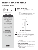
Model708Bus Extender Modules
allow you to increase the length
of LX‑Bus or Keypad Bus wiring
to a maximum of4,000ft while
providing immunity to wire noise.
Use708Modules in applications
such as long wire runs, noisy
environments, or where the bus run
is bundled with other wires, such as
telephone company wire.
The included pair of708modules
connect between the panel and
LX‑Bus or Keypad Bus devices.
These modules are referred
to as the Panel Moduleand
DevicesModulerespectively.
Compatibility
• All DMP XT and XR Series panels
• All DMP LX‑Bus and Keypad Bus
devices
What is Included?
• One pair of708Bus Extender
Modules in Universal Housings
• Hardware pack
1
MOUNT THE MODULES
The708comes in a high‑impact plastic housing that you can
mount directly to a wall, backboard, or other flat surface. For easy
installation, the back of the housing contains multiple holes that
allow you to mount themodule on a single‑gang switch box or
ring. Themodule can also be mounted in a DMP enclosure using
the standard3‑hole mounting pattern. Refer to Figure 2and
Figure 3as needed during installation.
1. Hold the plastic standos against the inside of the enclosure
side wall.
2. Insert the included Phillips head screws from the outside of
the enclosure into the standos. Tighten the screws.
3. Carefully snap the module onto the standos.
WIRE THE PANEL MODULE
2
Use18to22AWG wire to connect thePanel Moduledirectly to
the Keypad Bus or use a dual‑ended4‑wire harness to connect
directly to the LX‑Bus. This connection allows the module to
communicate with the panel and receive12VDC power. For more
information about wiring, refer to Wiring Specifications. Refer to
Figure 4andFigure 5when wiring themodule.
Caution: To avoid potential equipment damage from lightning
strikes, do not run LX‑Bus, Keypad Bus, or708bus wires
underground.
Connect to the LX‑Bus
At the Panel Module, connect wires to the RED, YEL, GRN, and
BLK terminals. Connect the red, yellow, green, and black wires to
the corresponding4‑wire harness leads. Connect the other end of
the harness to the LX‑Bus header.
Connect to the Keypad Bus
At the Panel Module, connect wires to the RED, YEL, GRN, and
BLK terminals. Connect the red, yellow, green, and black wires to
panel Terminal7, 8, 9, and10respectively.
Figure 1: 708 Modules
Figure 2: Mounting Hole Locations Figure 3: Stando Installation
Mounting
holes

2 708 INSTALLATION GUIDE | DIGITAL MONITORING PRODUCTS
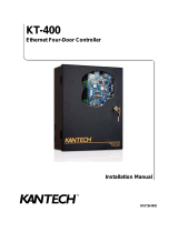
WIRE THE DEVICES MODULE
Observe polarity and connect a12VDC power supply, such as a Model505‑12, to Terminal1 (positive) and
Terminal6 (negative). Connect RED, YEL, GRN, and BLK Terminals from the Devices Moduleto devices
compatible with LX‑Bus or Keypad Bus connections. Refer to the appropriate module installation guide as
needed. For more information, refer to Figure 4andFigure 5.
Note: The modules should be powered by a 24‑hour power source that cannot be interrupted by a sensor
reset. It is not necessary to wire the negative power supply wire in common with the panel Terminal10
(black) wire.
4
3
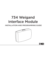
Use18‑24AWG straight, shielded, or twisted pair wire. Maximum wiring distance between the two modules
is4,000ft. Connect Terminal2,3,4,and5 from the Panel Moduleto the corresponding terminals on the
Devices Module. For more information, refer to Figure 4.
Note: The connection between the two modules is for data transfer only. Do not connect any devices or
power sources between the two modules.
CONNECT THE MODULES
RED YEL GRN BLK
1 2 3 4
5 6
CONNECT
TO PANEL
MODEL 708
W2
W1
1 2 3 4
5 6
MODEL 708
W4
W3
Devices Module
Panel Module
Balance Jumper
Balance Jumper
CONNECT
TO DEVICES
To LX-Bus or
Keypad Bus
To Devices
To 12 VDC
Power Supply
RED YEL GRN BLK
RED YEL GRN BLK
Balance Jumper
Balance Jumpers
RED
BLACK
Max 4,000 ft
Figure 4: Connecting the Modules

708 INSTALLATION GUIDE | DIGITAL MONITORING PRODUCTS 3
Figure 5: Full Wiring Diagram
AC
1
2
3
4 5 6 7
8
10
11 12 13 14
15
16 17 18
9
+B
BELL
GND
SMK
GND
RED
YEL
GRN
BLK
Z1
Z2 Z3 Z4
Z5
20
Z6
AC
-B
GND
19
GND
21
Z7
22
GND
23
Z8
24
Z9
25
Z10+
26
Z10-
PROG
LX500
LX600
LX700
LX800
LX900
RED YEL GRN BLK
1 2 3 4
5 6
CONNECT
TO PANEL
MODEL 708
W2
W1
1 2 3 4
5 6
MODEL 708
LX-BUS
RED
RED
BLACK
RED
BLACK
BLACK
W4
W3
Device 708
505-12 Power Supply
LX-Bus or
Keypad Bus
Compatible
Device
Panel 708
PANEL
CONNECT
TO DEVICES
RED YEL GRN BLK
RED YEL GRN BLK
DC
Max 4,000 ft

Designed, engineered, and
manufactured in Springfield, MO
using U.S. and global components.
LT-0585 20015
708 BUS EXTENDER
MODULES
Specifications
Operating Voltage 12VDC
Operating Current
Panel 708 10mA
Device 708 10mA
Dimensions 4.50” W x 2.75” H x 1.75” D
11.43 cm W x 6.99 cm H x 4.45 cm D
Maximum Distance 4,000 ft between the two modules
Compatibility
All DMP XT and XR Series panels
All DMP LX-Bus and Keypad Bus devices
RED
1 2 3 4
5 6
YEL GRN BLK
CONNECT
TO PANEL
MODEL 708
RED
1 2 3 4
5 6
YEL GRN BLK
CONNECT
TO DEVICES
MODEL 708
INTRUSION • FIRE • ACCESS • NETWORKS
2500 North Partnership Boulevard
Springfield, Missouri 65803-8877
800.641.4282 | DMP.com
ADDITIONAL INFORMATION
Wiring Specifications
DMP recommends using 18 or 22 AWG for all LX‑Bus and Keypad Bus connections. The maximum wire distance between
any module and the DMP Keypad Bus or LX‑Bus circuit is 10 feet. To increase the wiring distance, install an auxiliary
power supply, such as a DMP Model 505‑12. Maximum voltage drop between a panel or auxiliary power supply and any
device is 2.0 VDC. If the voltage at any device is less than the required level, add an auxiliary power supply at the end of
the circuit.
To maintain auxiliary power integrity when using 22‑gauge wire on Keypad Bus circuits, do not exceed 500 feet. When
using 18‑gauge wire, do not exceed 1,000 feet. Maximum distance for any bus circuit is 2,500 feet regardless of wire
gauge. Each 2,500 foot bus circuit supports a maximum of 40 LX‑Bus devices.
For additional information refer to the LX‑Bus/Keypad Bus Wiring Application Note (LT‑2031) and the 710 Bus Splitter/
Repeater Module Installation Guide (LT‑0310).
Balance the708Buses
Each708has two balance jumpers that ensure communication is balanced between the two modules. Refer to
Figure 4for balance jumper locations. Before changing module jumper settings, test the LX‑Bus or Keypad Bus to ensure
proper system communication.
For a Panel Moduleconnected to the LX‑Bus, run the Diagnostics LX‑Bus test to verify communication. For more
information about testing the LX‑Bus, refer to the Diagnostics Function section in the appropriate panel programming
guide.
For a Panel Moduleconnected to the Keypad Bus, ensure other Keypad Bus devices are working properly and check all
Panel Modulewiring connections.
If test results indicate faulty708communication, change the jumper settings as follows.
Install the jumper across the W1header on the Panel Module, then install the jumper across the W3header on the
Devices Module. If communication is still faulty, remove all four jumpers from the708modules.
Factory Jumper Settings
The708modules come installed from the factory with the jumper across the W2header on the Panel Moduleand across
the W4header on the Devices Module. Jumpers are not installed across the W1header on the Panel Module or the
W3header on the Devices Module.
/