Page is loading ...

Q7-951
Qseven Carrier Board
User’s Manual
A14720205

Copyright
This publication contains information that is protected by copyright. No part of it
may be reproduced in any form or by any means or used to make any transfor-
mation/adaptation without the prior written permission from the copyright hold-
ers.
This publication is provided for informational purposes only. The manufacturer
makes no representations or warranties with respect to the contents or use
of this manual and specifically disclaims any express or implied warranties of
merchantability or fitness for any particular purpose. The user will assume the
entire risk of the use or the results of the use of this document. Further, the
manufacturer reserves the right to revise this publication and make changes to
its contents at any time, without obligation to notify any person or entity of such
revisions or changes.
© 2012. All Rights Reserved.
Trademarks
All trademarks and registered trademarks of products appearing in this manual
are the properties of their respective holders.

FCC and DOC Statement on Class B
This equipment has been tested and found to comply with the limits for a Class B
digital device, pursuant to Part 15 of the FCC rules. These limits are designed to
provide reasonable protection against harmful interference when the equipment
is operated in a residential installation. This equipment generates, uses and can
radiate radio frequency energy and, if not installed and used in accordance with
the instruction manual, may cause harmful interference to radio communications.
However, there is no guarantee that interference will not occur in a particular
installation. If this equipment does cause harmful interference to radio or televi-
sion reception, which can be determined by turning the equipment off and on,
the user is encouraged to try to correct the interference by one or more of the
following measures:
• Reorientorrelocatethereceivingantenna.
• Increasetheseparationbetweentheequipmentandthereceiver.
• Connecttheequipmentintoanoutletonacircuitdifferentfromthattowhich
the receiver is connected.
• ConsultthedealeroranexperiencedradioTVtechnicianforhelp.
Notice:
1. The changes or modifications not expressly approved by the party responsible
for compliance could void the user’s authority to operate the equipment.
2. Shielded interface cables must be used in order to comply with the emission
limits.

Table of Contents
Copyright ������������������������������������������������������������������������������������������� 2
Trademarks ���������������������������������������������������������������������������������������� 2
FCC and DOC Statement on Class B ���������������������������������������������� 3
About this Manual ����������������������������������������������������������������������������� 6
Warranty ������������������������������������������������������������������������������������������ 6
Static Electricity Precautions ������������������������������������������������������������� 7
Safety Measures ��������������������������������������������������������������������������������� 7
About the Package ���������������������������������������������������������������������������� 8
Before Using the System Board �������������������������������������������������������� 8
Chapter 1 - Introduction ������������������������������������������������������������������ 9
Specifications ���������������������������������������������������������������������������������� 9
Chapter 2 - Hardware Installation �������������������������������������������������� 11
System Board Layout �������������������������������������������������������������������� 11
Jumper Settings ����������������������������������������������������������������������������� 12
COM2 RS232/RS422/RS485 Select ��������������������������������������������� 12
USB Power Select ��������������������������������������������������������������������� 13
Panel Power Select ������������������������������������������������������������������� 14
Super IO Select ����������������������������������������������������������������������� 15
Power-on Select ����������������������������������������������������������������������� 16
Backlight Control Level Select ���������������������������������������������������� 17
AT Mode Select ������������������������������������������������������������������������ 18
Rear Panel I/O Ports ��������������������������������������������������������������������� 19
DC-in 12V ������������������������������������������������������������������������������� 20
Serial (COM) Ports ������������������������������������������������������������������� 21
VGA Port ��������������������������������������������������������������������������������� 22
RJ45 LAN Port ������������������������������������������������������������������������� 23
Universal Serial Bus Connectors ������������������������������������������������� 24
Audio �������������������������������������������������������������������������������������� 25

Internal I/O Connectors ................................................................ 26
S/PDIF Connector ..................................................................... 26
LVDS LCD Panel Connector and LCD/Inverter Power Connector ...... 27
Digital I/O Connector and Digital I/O Power Connector ................. 29
Mini PCIe ................................................................................ 30
SATA (Serial ATA) Connectors .................................................... 31
Cooling Fan Connectors ............................................................. 32
Chassis Intrusion Connector ...................................................... 33
Standby Power LED .................................................................. 34
WAN LED, LAN LED, PAN LED .................................................... 35
Front Panel Connectors ............................................................. 36
Battery ................................................................................... 37
MXM Connector ........................................................................ 38
I
2
C Connector .......................................................................... 41
Can-bus Connector ................................................................... 42
USB Client Connector ............................................................... 43
SM bus ................................................................................... 44
LPC Connector ......................................................................... 45
External Power......................................................................... 46

1
6
Introduction
About this Manual
An electronic file of this manual is included in the CD. To view the user’s manual
in the CD, insert the CD into a CD-ROM drive. The autorun screen (Main Board
Utility CD) will appear. Click “User’s Manual” on the main menu.
Warranty
1. Warranty does not cover damages or failures that arised from misuse of the
product, inability to use the product, unauthorized replacement or alteration
of components and product specifications.
2. The warranty is void if the product has been subjected to physical abuse,
improper installation, modification, accidents or unauthorized repair of the
product.
3. Unless otherwise instructed in this user’s manual, the user may not, under
any circumstances, attempt to perform service, adjustments or repairs on the
product, whether in or out of warranty. It must be returned to the purchase
point, factory or authorized service agency for all such work.
4. We will not be liable for any indirect, special, incidental or consequencial
damages to the product that has been modified or altered.

1
7
Introduction
Static Electricity Precautions
It is quite easy to inadvertently damage your PC, system board, components
or devices even before installing them in your system unit. Static electrical dis-
charge can damage computer components without causing any signs of physical
damage. You must take extra care in handling them to ensure against electro-
static build-up.
1. To prevent electrostatic build-up, leave the system board in its anti-static bag
until you are ready to install it.
2. Wear an antistatic wrist strap.
3. Do all preparation work on a static-free surface.
4. Hold the device only by its edges. Be careful not to touch any of the compo-
nents, contacts or connections.
5. Avoid touching the pins or contacts on all modules and connectors. Hold
modules or connectors by their ends.
Important:
Electrostatic discharge (ESD) can damage your processor, disk drive and
other components. Perform the upgrade instruction procedures described
at an ESD workstation only. If such a station is not available, you can
provide some ESD protection by wearing an antistatic wrist strap and
attaching it to a metal part of the system chassis. If a wrist strap is
unavailable, establish and maintain contact with the system chassis
throughout any procedures requiring ESD protection.
Safety Measures
To avoid damage to the system:
• UsethecorrectACinputvoltagerange.
To reduce the risk of electric shock:
• Unplug the power cord before removing the system chassis cover for instal-
lation or servicing. After installation or servicing, cover the system chassis
before plugging the power cord.
Battery:
• Dangerofexplosionifbatteryincorrectlyreplaced.
• Replace only with the same or equivalent type recommend by the manufac-
turer.
• Disposeofusedbatteriesaccordingtolocalordinance.

1
8
Introduction
About the Package
The system board package contains the following items. If any of these items are
missing or damaged, please contact your dealer or sales representative for as-
sistance.
One motherboard
One Serial ATA data cable
One power cable
One COM cable
One DVD
One QR (Quick Reference)
The system board and accessories in the package may not come similar to the
information listed above. This may differ in accordance to the sales region or
models in which it was sold. For more information about the standard package in
your region, please contact your dealer or sales representative.
Before Using the System Board
Before using the system board, prepare basic system components.
If you are installing the system board in a new system, you will need at least the
following internal components.
• A CPU
• Memory module
• Storage devices such as hard disk drive, CD-ROM, etc.
You will also need external system peripherals you intend to use which will nor-
mally include at least a keyboard, a mouse and a video display monitor.

1
9
Introduction
Chapter 1 - Introduction
Specifications
Graphics
Audio
Serial ATA
TPM
I/O Chip
Damage Free
Intelligence
Temperature
Humidity
Rear Panel I/O
Ports
• Chrontel CH7317B (SDVO to RGB DAC)
• Realtek ALC262 audio codec
• 2-channel audio output
• Two Serial ATA ports
• SATA speed up to 3Gb/s (SATA 2.0)
• Inneon SLB9635TT12
• Winbond 83627DHG-P controller
• LPC interface
• Supports system fan
• Default I/O port address “2Eh”
• Monitors system temperature and overheat alarm
• Monitors system fan speed and failure alarm
• 0
o
C to 60
o
C
• Operating: 10% to 90%
• 1 12V DC-in jack
• 1 DB-15 VGA port
• 1 DB-9 RS232 serial port
• 2 USB 2.0/1.1 ports
• 1 RJ45 LAN port
• 1 line-out jack

1
10
Introduction
I/O Connectors
Expansion Slots
Board to board
Connectors
PCB
• 2connectorsfor4externalUSB2.0/1.1ports
• 1connectorforanexternalRS232/422/485serialport
• 1LPCconnector
• 1I
2
C connector
• 1CAN-busconnector
• 1USBclientconnector
• 1LVDSLCDpanelconnector
-18/24-bitsinglechannel
• 1LCD/inverterpowerconnector
• 18-bitDigitalI/Oconnector
• 1DigitalI/Opowerconnector
• 1audioconnectorforline-in,line-outandmic-injacks
• 1S/PDIFconnector
• 2SerialATAconnectors
• 14-pin12V/5Vpowerconnector
• 1chassisintrusionconnector
• 1frontpanelconnector
• 1fanconnector
• 1SD/SDIO/MMCsocket
• 1miniPCIesocket
• OneMXMconnector
• 3.5”formfactor
• 102mm(4.02”)x147mm(5.79”)

11
2
Hardware Installation
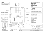
System Board Layout
Chapter 2 - Hardware Installation
VGA
COM 1
DIO
1
1
DIO
power
USB 0
USB 1
LAN
Line-out
1
7
1
7
SATA 1
SATA 0
Realtek
ALC262
Front
audio
1
9
10
1
S/PDIF
1
1
2
9
COM 2
LVDS LCD panel
40
12
39
1
LCD/Inverter
power
8
Battery
1
2
12
11
Front panel
1
5
2
6
Panel power
select (JP5)
USB 2-3
USB 4-5
1
2
9
10
9
10
1
USB Client
1
USB 2-5 power
select (JP4)
1
2
DC-IN
12V
1 2
3 4
5 6
COM 2
422/485 select
(JP1)
RS232/
MXM
1
External power
1
System fan
1
CAN bus
Mini PCIe
LPC
1
Chassis
intrusion
1
I C
1
1
1
Standby
power LED
WAN LED
LAN LED
PAN LED
Super IO Select
(JP6)
2
1
Backlight
level
select
(JP7)
1
2
ON
1
AT Mode
Select (SW1)
SM Bus
(J8)
USB 0-1
power
select
(JP3)
Power-on
select (JP2)

12
2
Hardware Installation
Jumper Settings
COM2 RS232/RS422/RS485 Select
1-2 On: RS232
(default)
3-4 On: RS422
Full Duplex
5-6 On: RS485
JP1 is used to congure COM 2 to RS232, RS422 (Full Duplex) or RS485.
The pin function of COM 2 will vary according to the jumper’s setting.
JP1
RS232 RS422
Full Duplex
RS485
COM 2
JP1
1
5
3
2
4
6
1
5
3
2
4
6
1
5
3
2
4
6
COM2
1
9
2
DCD-
TD
RD
DTR-
GND
RTS-
DSR-
CTS-
RI-
1
9
2
DATA+
N.C.
DATA-
N.C.
N.C.
N.C.
N.C.
N.C.
N.C.
1
9
2
RXD+
N.C.
RXD-
N.C.
N.C.
N.C.
N.C.
N.C.
N.C.

13
2
Hardware Installation
JP3 (for USB 0-1) and JP4 (for USB 2-5) are used to select the power of the USB
ports. Selecting +5V_standby will allow you to use a USB keyboard to wake up
the system.
Important:
If you are using the Wake-On-USB Keyboard/Mouse function for 2 USB
ports, the +5V_standby power source of your power supply must sup-
port ≥1.5A. For 3 or more USB ports, the +5V_standby power source of
your power supply must support ≥2A.
USB Power Select
USB 0-1
(JP3)
3
1
2 3 12
2-3 On: +5V_
standby
1-2 On: +5V
(default)
1
3
2
1
3
2
2-3 On: +5V_
standby
1-2 On: +5V
(default)
USB 2-5
(JP4)

14
2
Hardware Installation
Panel Power Select
JP5
JP5 is used to select the power supplied to the LCD panel.
Important:
Before powering-on the system, make sure JP5’s setting matches the
LCD panel’s specication. Selecting the incorrect voltage will seriously
damage the LCD panel.
1-2 On:
+12V
1
5
3
2
4
6
3-4 On: +5V
1
5
3
2
4
6
5-6 On:
+3.3V
(default)
1
5
3
2
4
6

15
2
Hardware Installation
Super IO Select
JP6
3
1
2
3
1
2
2-3 On: Disable
(default)
1-2 On: Enable
JP6 is used to select enable or disable the super IO select.

16
2
Hardware Installation
Power-on Select
JP2
3
1
3
1
2-3 On: Power-
on After G3
(default)
1-2 On: Power-on
via power button
To power-on after G3:
1. Set JP2 pins 2 and 3 to On.
2. Setthe“AfterG3”eldtoPower Off/WOL.
3. Set the “GbE Wake Up From S5” to Enabled.
TheBIOS eldsarein the“SouthBridge Conguration”submenu (Chipsetmenu)
of the AMI BIOS utility.
Topower-onviaACPower:
1. Set JP2 pins 2 and 3 to On.
2. Setthe“AfterG3”eldtoPower On.

17
2
Hardware Installation
Backlight Control Level Select
JP7
3
1
2
3
1
2
2-3 On: +3.3V
1-2 On: +5V
(default)
JP7isusedtoselectthebacklightcontrollevel+5Vor+3.3V.

18
2
Hardware Installation
AT Mode Select
SW1
1 Off: Disable
(default)
1 On: Enable
SW1 is used to select switch 1 to enable or disable the function.
1
ON
2 3 4 5 6
1
ON
2 3 4 5 6
2
ON
1
2
ON
1
2
ON
1
2
ON
1
1
ON
2 3 4 5 6
1
ON
2 3 4 5 6
2
ON
1
2
ON
1
2
ON
1
2
ON
1

19
2
Hardware Installation
Rear Panel I/O Ports
The rear panel I/O ports consist of the following:
• DC-in
• VGA port
• COM1 port
• LAN port
• 2 USB ports
• Line-out jack
USB LANDC-in COM 1VGA Line-out

20
2
Hardware Installation
DC-in 12V
This jack provides maximum of 60W power and is considered a low power solu-
tion. Connect a DC power cord to this jack. Use a power adapter with 12V DC
output voltage. Using a voltage higher than the recommended one may fail to
boot the system or cause damage to the system board.
/