Page is loading ...

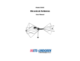
Model 3140B
BiConiLog™ Antenna
User Manual
Model 3140B mounted onto a 7-TR tripod (not included)

ETS-Lindgren L.P. reserves the right to make changes to any product described
herein in order to improve function, design, or for any other reason. Nothing
contained herein shall constitute ETS-Lindgren L.P. assuming any liability
whatsoever arising out of the application or use of any product or circuit
described herein. ETS-Lindgren L.P. does not convey any license under its
patent rights or the rights of others.
© Copyright 2000–2010 by ETS-Lindgren L.P. All Rights Reserved. No part
of this document may be copied by any means without written permission
from ETS-Lindgren L.P.
Trademarks used in this document: The ETS-Lindgren logo, MiniMast, and
BiConiLog are trademarks of ETS-Lindgren L.P.
Revision Record | MANUAL,MODEL 3140 | Part #399258, Rev. E
Revision Description Date
A Initial Release November, 2000
B Edits/updates January, 2002
C Edits/updates January, 2003
D Edits/updates May, 2003
E Rebrand May, 2010
ii |

Table of Contents
Notes, Cautions, and Warnings ................................................ v
1.0 Introduction .......................................................................... 7
About Mounting the Model 3140B ................................................................. 9
7-TR Tripod Positioner........................................................................... 9
ETS-Lindgren Product Information Bulletin ................................................. 10
2.0 Maintenance ....................................................................... 11
About Calibration ......................................................................................... 11
Service Procedures ..................................................................................... 11
3.0 Specifications ..................................................................... 13
Electrical Specifications ............................................................................... 13
Physical Specifications ................................................................................ 13
4.0 Assembly Instructions ...................................................... 15
Model 3140B Components .......................................................................... 15
Model 3140B Assembled ............................................................................. 16
Steps to Assemble the Model 3140B ........................................................... 17
Attach Bow Tie Elements..................................................................... 17
Attach T Leg Elements ........................................................................ 19
Attach Diagonal Struts ......................................................................... 21
Attach V Elements ............................................................................... 22
5.0 Mounting Instructions ....................................................... 23
Included Mounting Adapters ........................................................................ 23
Using Included Adapters to Mount to an Offset Boom ................................. 24
Attach Included Mounting Adapters to Model 3140B .......................... 24
Attach Model 3140B to an ETS-Lindgren Offset Boom ....................... 25
Mounting Illustrations ................................................................................... 26
Model 3140B on 7-TR Tripod Positioner ............................................. 26
Model 3140B on Model 2075 MiniMast ............................................... 27
Model 3140B on Model 2070/2071 Antenna Positioning Mast ............ 28
Additional Mounting Options ........................................................................ 29
7-TR and Mast Mounting Options ........................................................ 29
2x2 Boom Mounting Options ............................................................... 30
6.0 Application ......................................................................... 31
| iii

7.0 Typical Data ........................................................................ 33
Model 3140B Typical VSWR ....................................................................... 33
Model 3140B Typical Antenna Factors ........................................................ 34
Model 3140B Gain ....................................................................................... 35
Model 3140B Typical Forward Power (FP) .................................................. 36
Typical 1 Meter FP Based on 1 Meter Antenna Factor ....................... 37
Typical 3 Meter FP Based on 3 Meter Antenna Factor ....................... 38
Typical 3 Meter FP Over Ferrite Tile.................................................... 39
Typical 3 Meter FP Measured Over Conducting Ground .................... 40
Appendix A: Warranty ............................................................. 41
iv |

Notes, Cautions, and Warnings
Note: Denotes helpful information intended to
provide tips for better use of the product.
Caution: Denotes a hazard. Failure to follow
instructions could result in minor personal injury
and/or property damage. Included text gives proper
procedures.
Warning: Denotes a hazard. Failure to follow
instructions could result in SEVERE personal injury
and/or property damage. Included text gives proper
procedures.
See the ETS-Lindgren Product Information Bulletin for safety,
regulatory, and other product marking information.
| v

vi |
This page intentionally left blank.

1.0 Introduction
The ETS-Lindgren
Model 3140B BiConiLog
TM
is a
high-field antenna in the
bow tie/log periodic family,
providing the highest
field-to-power ratio at low
frequencies of any of the
BiConiLog antennas. The
Model 3140B is designed
specifically to generate the field
levels required for
immunity/susceptibility tests
required by standards such as
IEC/EN 61000-4-3 using the
lowest amount of input power
possible.
A BiConiLog antenna combines a broadband biconical-like bow tie antenna with
a standard log periodic dipole array (LPDA) to replace the traditional use of two
antennas in the 26 MHz to 3000 MHz electromagnetic compatibility (EMC) test
frequency range. Many EMC antennas are variations of a standard tuned dipole,
which must be nearly half a wavelength long to transmit or receive energy most
efficiently; at 26 MHz, a tuned dipole would have to be approximately 5.3 meters
long, 4.6 meters long at 30 MHz, and 2.8 meters long at 50 MHz. This is
unwieldy for many anechoic chambers and test sites. The end plates of the
Model 3140B T bow ties make the bow tie antenna segment look like an antenna
twice as long as the actual 1.6 meter length. The result is about a 10 dB
improvement in low frequency transmit gain compared to a regular bow tie of the
same length.
Although bow ties have been used for all of the elements on some log periodic
antenna designs in the past, in EMC applications the advantage gained is an
extension of the useful low frequency range of the typical LPDA from 100 MHz
down to 26 MHz. At 26 MHz, an efficient single dipole type antenna must be over
five meters long, whereas suitable performance is obtained here with a 1.6 meter
bow tie. A simple wire outline bow tie antenna is narrowband compared to a
sheet bow tie or biconical, so struts are added to the Model 3140B bow ties to
better simulate the broadband sheet bow tie.
Introduction | 7

The unique feature of the Model 3140B is the T bow tie elements. A T bow tie
increases the equivalent dipole electrical length, thereby decreasing resonant
frequency and increasing efficiency in the 20 MHz to 60 MHz range. Similarly, a
regular bow tie has a lower resonant frequency than an equal length single-wire
dipole. The T bow tie has the first resonance at a frequency where the length is
about 0.22
λ, a regular bow tie at a length of 0.3λ, and a tuned dipole at about
0.48
λ. Thus at 50 MHz the 1.4 meter long T bow tie of the Model 3140B behaves
like a 2.8 meter tuned dipole. Cross-polar radiation is minimized because current
flow on one of the T end frames is almost exactly cancelled by the
oppositely-phased current on the other T end.
The standard self-balun feed of the log periodic also provides a matched
balanced feed to the bow tie elements. To prevent cable pickup below 100 MHz
and to improve matching to the bow tie elements, the Model 3140B contains a
balun transformer which acts as a common-mode choke to keep unbalanced
current off the coaxial feed cable outer shield, as well as adding some additional
inductance to improve impedance matching to the bow ties. Even though the
Model 3140B is highly balanced (symmetry +/- 0.5 dB), in vertically polarized
measurements cable position can effect results, so it is recommended that the
cable be suspended horizontally back from the antenna at least one meter before
any vertical drop. Below 150 MHz bow tie radiation dominates with a dipole-like
pattern, while above 150 MHz the radiation in the plane of the elements is
directional.
The Model 3140B is designed only for immunity testing. The large size
of the antenna makes it impractical for emissions testing where height
scanning is required, and the bow tie end plates increase the
measurement uncertainty when the antenna is polarized vertically. For
that reason, individual calibrations are not provided for the
Model 3140B.
8 | Introduction

About Mounting the Model 3140B
The Model 3140B can be mounted on the 2-in square booms of these
ETS-Lindgren products:
• Model 7-TR Tripod Positioner
• Model 2075 MiniMast™
• Model 2070/2071 Antenna Positioning Mast
See Mounting Illustrations on page 26 for diagrams showing the
Model 3140B mounted to these ETS-Lindgren products.
For the variety of mounting options available for the Model 3140B, see
Mounting Instructions on page 23.
7-TR TRIPOD POSITIONER
ETS-Lindgren offers the non-metallic, non-reflective Model 7-TR for use at both
indoor and outdoor EMC test sites.
Constructed of PVC and fiberglass
components, providing increased stability
for physically large antennas. The unique
design allows for quick assembly,
disassembly, and convenient storage.
Allows several different configurations,
including options for manual or pneumatic
polarization. Quick height adjustment and
locking wheels provide ease of use during
testing. Maximum height is 2.17 m (85.8 in),
with a minimum height of 0.8 m (31.8 in).
This tripod can support a 13.5 kg (30 lb)
load.
Introduction | 9

ETS-Lindgren Product Information Bulletin
See the ETS-Lindgren Product Information Bulletin included with your shipment
for the following:
• Warranty information
• Safety, regulatory, and other product marking information
• Steps to receive your shipment
• Steps to return a component for service
• ETS-Lindgren calibration service
• ETS-Lindgren contact information
10 | Introduction

2.0 Maintenance
Before performing any maintenance,
follow the safety information in the
ETS-Lindgren Product Information
Bulletin included with your shipment.
Maintenance of the Model 3140B is
limited to external components such as
cables or connectors.
If you have any questions concerning
maintenance, contact ETS-Lindgren
Customer Service.
WARRANTY
About Calibration
The Model 3140B BiConiLog
TM
Antenna was designed for immunity
testing, so the generated field is measured with a calibrated
field probe, not the Model 3140B. For that reason, it is not required
that the Model 3140B be recalibrated regularly. If you would like to
have your Model 3140B antenna verified or serviced please contact
ETS-Lindgren Calibration.
See the Product Information Bulletin included with your shipment for information
on ETS-Lindgren calibration services.
Service Procedures
For the steps to return a system or system component to ETS-Lindgren for
service, see the Product Information Bulletin included with your shipment.
Maintenance | 11

This page intentionally left blank.
12 | Maintenance

3.0 Specifications
Electrical Specifications
Frequency Range: 26 MHz–3000 MHz
Input Impedance: 50 Ω
VSWR (Average): 2:1
CW Power (Average):
• 26 MHz to 150 MHz = 750 W
• 150 MHz to 600 MHz = 500 W
• 600 MHz to 1 GHz = 365 W
• 1 GHz to 3 GHz = 200 W
Symmetry: +/- 0.5 dB
Connector: Type N female
Physical Specifications
Height (T Bow Tie): 76.65 cm (30.18 in)
Width (T Bow Tie): 161.5 cm (63.60 in)
Depth (Length): 151.3 cm (59.6 in)
Weight: 10 kg (22 lb)
Specifications | 13

This page intentionally left blank.
14 | Specifications

4.0 Assembly Instructions
Before connecting any components, follow the
safety information in the ETS-Lindgren
Product Information Bulletin included with your
shipment.
Model 3140B Components
The Model 3140B BiConiLog™ Antenna consists of the following:
• Antenna
• Bow tie elements (2)
• Long T leg elements (2)
• Diagonal struts (4)
• V elements (2)
• Boom assembly
• Mount knobs (2): one 7/8-in (104169) and one 1/4-in (104136)
• Polarizing adapters (100989) for booms with 7/8-in mount holes (2)
• Thread inserts (105861B) 7/8 in-to-1/4 in (2)
Assembly Instructions | 15

Model 3140B Assembled
16 | Assembly Instructions

Steps to Assemble the Model 3140B
To eliminate stress and prevent damage to the
balun box connection, you must support the
antenna while attaching the bow tie elements.
A
TTACH
B
OW
T
IE
E
LEMENTS
1. Place the bow tie vertically on the floor and hold the antenna
horizontally. See illustration on next page.
2. Fit the bow tie into one side of the balun.
3. Insert and tighten the knob.
4. Carefully place the antenna in a vertical position with the feet of the
balun box level and on a flat surface.
5. Repeat steps 2 and 3 to attach the second bow tie element to the
balun box.
Assembly Instructions | 17

18 | Assembly Instructions

ATTACH T LEG ELEMENTS
6. Insert one long T leg element into the clamp and tighten the clamp
screws. See illustration on next page.
7. Repeat for second T leg element.
Assembly Instructions | 19

20 | Assembly Instructions
/