Page is loading ...

October
1981
FORM:
OM-1516C
Effective
With
Serial
No.
JB512073
MODEL
SWINGARC
SINGLE
12
SWINGARC
SINGLE
16
OWN
ERS
MANUAL
inulliEl
MILLER
ELECTRIC
MFG.
CO.
718
S.
BOUNDS
ST.
P.O.
Box
1079
APPLETON,
WI
54912
usA
ADDITIONAL
COPY
PRICE
85
CENTS
NWSA
CODE
NO.
4579
PRINTED
IN
U.S.A.

LIMITED
WARRANTY-Subject
to
the
terms
and
conditions
hereof,
Miller
Electric
Mfg.
Co.,
Appleton,
Wisconsin
warrants
to
its
Distributor/Dealer
that
all
new
and
unused
Equipment
furnished
by
Miller
is
free
from
defect
in
workmanship
and
material
as
of
the
time
and
place
of
delivery
by
Miller.
No
war
ranty
is
made
by
Miller
with
respect
to
engines,
trade
ac
cessories
or
other
items
manufactured
by
others.
Such
engines,
trade
accessories
and
other
items
are
sold
subject
to
the
warranties
of
their
respective
manufacturers,
if
any
.
All
engines
are
warranted
by
their
manufacturer
for
one
year
from
date
of
original
purchase.
Except
as
specified
below,
Millers
warranty
does
not
apply
to
components
having
normal
useful
life
of
less
than
one
Ill
year,
such
as
spot
welder
tips,
relay
and
contactor
points,
MILLERMATIC
parts
that
come
in
contact
with
the
welding
wire
including
nozzles
and
nozzle
insulators
where
failure
does
not
result
from
defect
in
workmanship
or
material.
Miller
shall
be
required
to
honor
warranty
claims
on
war
ranted
Equipment
in
the
event
of
failure
resulting
from
a
defect
within the
following
periods
from
the
date
of
delivery
of
Equip
ment
to
the
original
user:
1.
Arc
welders,
power
sources
and
components
.
.
1
year
2.
Original
main
power
rectifiers
3
years
Ilabor
-
1
year
onlyl
3.
All
welding
guns
and
feeder/guns
90
days
4.
All
other
Miltermatic
Feeders
1
year
5.
Replacement
or
repair
parts,
exclusive
of
labor
.
60
days
6.
Batteries
6
months
provided
that
Miller
is
notified
in
writing
within
thirty
(301
days
of
the
date
of
such
failure.
As
a
matter
of
general
policy
only,
Miller
may
honor
claims
submitted
by
the
original
user
within
the
foregoing
periods.
In
the
case
of
Millers
breach
of
warranty
or
any
other
duty
with
respect
to
the
quality
of
any
goods,
the
exclusive
remedies
therefore
shall
be,
at
Millers
option
(1)
repair
or
12)
replacement
or,
where
authorized
in
writing
by
Miller
in
appropriate
cases,
(3)
the
reasonable
cost
of
repair
or
replacement
at
an
authorized
Miller
service
station
or
(41
payment
of
or
credit
for
the
purchase
price
(less
reasonable
depreciation
based
upon
actual
use(
Upon
return
of
the
goods
at
Customers
risk
and
expense.
Upon
receipt
of
notice
of
apparent
defect
or
failure,
Miller
shall
instruct
the
clai
mant
on
the
warranty
claim
procedures
to
be
followed.
ANY
EXPRESS
WARRANTY
NOT
PROVIDED
HEREIN
AND
ANY
IMPLIED
WARRANTY,
GUARANTY
OR
REPRESENTA
TION
AS
TO
PERFORMANCE,
AND
ANY
REMEDY
FOR
BREACH
OF
CONTRACT
WHICH,
BUT
FOR
THIS
PROVISION,
MIGHT
ARISE
BY
IMPLICATION,
OPERATION
OF
LAW,
CUSTOM
OF
TRADE
OR
COURSE
OF
DEALING,
INCLUDING
ANY
IMPLIED
WARRANTY
OF
MERCHANTABILITY
OR
OF
FITNESS
FOR
PARTICULAR
PURPOSE,
WITH
RESPECT
TO
ANY
AND
ALL
EQUIPMENT
FURNISHED
BY
MILLER
IS
EX
CLUDED
AND
DISCLAIMED
BY
MILLER.
EXCEPT
AS
EXPRESSLY
PROVIDED
BY
MILLER
IN
WRITING,
MILLER
PRODUCTS
ARE
INTENDED
FOR
ULTIMATE
PURCHASE
BY
COMMERCIAL/INDUSTRIAL
USERS
AND
FOR
OPERATION
BY
PERSONS
TRAINED
AND
EXPERIENCED
IN
THE
USE
AND
MAINTENANCE
OF
WELDING
EQUIPMENT
AND
NOT
FOR
CONSUMERS
OR
CONSUMER
USE.
MILLER
WARRANTIES
DO
NOT
EXTEND
TO,
AND
NO
RESELLER
IS
AUTHORIZED
TO EXTEND
MILLERS
WARRANTIES
TO,
ANY
CONSUMER.
EFFECTIVE:
JUNE
1,
1979
This
warranty
supersedes
all
previous
MILLER
warranties
and
is
ex
clusive
with
no
other
guarantees
or
warranties
expressed
or
implied.
~
.,~
~
LIMITED
WARRANTY
ff1:-
*
*

TABLE
OF
CONTENTS
Section
No.
Page
No.
SECTION
1
-
SAFETY
RULES
FOR
OPERATION
OF
ARC
WELDING
POWER
SOURCE
1
-
1.
Introduction
1
1
-
2.
General
Precautions
1
1
-3.
ArcWelding
4
1
-
4.
Standards
Booklet
Index
5
SECTION
2
-
INTRODUCTION
2
-
1.
General
Information
And
Safety
7
2
-
2.
Receiving-Handling
7
2
-
3.
Description
7
SECTION
3
-
INSTALLATION
3
-
1.
Location
And
Assembly
7
3
-
2.
Drive
Motor
9
3-3.
Installation
Of
Wire
Support
9
3
-
4.
Reinstallation
Of
Hub
Assembly
9
3-5.
Installation
Of
Wire
Reel
9
3
-6.
DriveRollAndWireGuidelnstallation
10
3
-7.
Water
Connections
11
3
-
8.
Welding
Gun
Connections
11
3
-
9.
Shielding
Gas
Connections
12
3-10.
Boom
Adjustments
12
3-11.
WirePulley
12
3-12.
Motor
Control
Connections
12
3-13.
Gun
Trigger
Connection
12
3-14.
WeldCableConnection
13
3-15.
Remote
Control
Connections
13
3-16.
Installation
Of
Spool-Type
Wire
13
3-17.
Installation
Of
Reel-Type
Wire
13
3-18.
Adjustment
Of
Hub
Tension
13
3-19.
115
Volts!
Contactor
Connections
13
SECTION
4
-
FUNCTION
OF
CONTROLS
4
-
1.
Power
Switch
13
4
-2.
Remote
Control
Receptacle
And
Switch
13
4-3.
PurgeButton
13
4
-
4.
Inch
Button
13
4
-
5.
Wire
Speed
Control
14
4-6.
Start
Switch
14
4
-
7.
Retract-Feed
Switch
14
4-8.
Reset
Circuit
Breaker
14
4-9.
Burnback
Control
14
SECTION
5
-
SEQUENCE
OF
OPERATION
5-
1.
WeldingWireThreading
14
5
-
2.
Gas
Metal-Arc
Welding
(GMAW)
15
5
-
3.
Shutting
Down
15
SECTION
6
-
MAINTENANCE
6
-
1.
Inspection
And
Upkeep
15
6-2.
CleaningOfDriveRolls
15
6-3.
Fuse
15
6
-
4.
Brush
Inspection
&
Replacement
16
SECTION
7
-
TROUBLESHOOTING


SECTION
1
-
SAFETY
RULES
FOR
OPERATION
OF
ARC
WELDING
POWER
SOURCE
1-1.
INTRODUCTION
-
We
learn
by
experience.
Learning
safety
through
personal
experience,
like
a
child
touching
a
hot
stove
is
harmful,
wasteful,
and
un
wise.
Let
the
experience
of
others
teach
you.
Safe
practices
developed
from
experience
in
the
use
of
welding
and
cutting
are
described
in
this
manual.
Research,
development,
and
field
experience
have
evolved
reliable
equipment
and
safe
installation,
opera-
tion,
and
servicing
practices.
Accidents
occur
when
equipment
is
improperly
used
or
maintained.
The
reason
for
the
safe
practices
may
not
always
be
given.
Some
are
based
on
common
sense,
others
may
require
technical
volumes
to
explain.
It
is
wiser
to
follow the
rules.
Read
and
understand
these
safe
practices
before
at
tempting
to
install,
operate,
or
service
the
equipment.
Comply
with these
procedures
as
applicable
to
the
par
ticular
equipment
used
and
their
instruction
manuals,
for
personal
safety
and
for
the
safety
of
others.
Failure
to
observe
these
safe
practices
may
cause
serious
injury
or
death.
When
safety
becomes
a
habit,
the
equipment
can
be
used
with
confidence.
These
safe
practices
are
divided
into
two
Sections:
1
-
General
Precautions,
common
to
arc
welding
and
cutting;
and
2
-
Arc
Welding
(and
Cutting)
(only).
Reference
standards:
Published
Standards
on
safety
are
also
available
for
additional
and
more
complete
pro
cedures
than
those
given
in
this
manual.
They
are
listed
in
the
Standards
Index
in
this
manual.
ANSI
Z49.1
is
the
most
complete.
The
National
Electrical
Code,
Occupational
Safety
and
Health
Administration,
local
industrial
codes,
and
local
inspection
requirements
also
provide
a
basis
for
equip
ment
installation,
use,
and
service.
1-2.
GENERAL
PRECAUTIONS
A.
Burn
Prevention
Wear
protective
clothing
-
leather
(or
asbestos)
gauntlet
gloves,
hat,
and
high
safety-toe
shoes.
Button
shirt
collar
and
pocket
flaps,
and
wear
cuff
less
trousers
to
avoid
entry
of
sparks
and
slag.
Wear
helmet
with
safety
goggles
or
glasses
with
side
shields
underneath,
appropriate
filter
lenses
or
plates
(protected
by
clear
cover
glass).
This
is
a
MUST
for
welding
or
cutting,
(and
chipping)
to
protect
the
eyes
from
radiant
energy
and
flying
metal.
Replace
cover
gla~s
when
broken,
pitted,
or
spattered.
See
1-3A.2.
Avoid
oily
or
greasy
clothing.
A
spark
may
ignite
them.
Hot
metal
such
as
electrode
stubs
and
workpieces
should
never
be
handled
without
gloves.
Medical
first
aid
and
eye
treatment.
First
aid
facilities
and
a
qualified
first
aid
person
should
be
available
for
each
shift
unless
medical
facilities
are
close
by
for
im
mediate
treatment
of
flash
burns
of
the
eyes
and
skin
burns.
Ear
plugs
should
be
worn
when
working
on
overhead
or
in
a
confined
space.
A
hard
hat
should
be
worn
when
others
work
overhead.
Flammable
hair
preparations
should
not
be
used
by
per
sons
intending
to
weld
or
cut.
B.
Toxic
Fume
Prevention
Adequate
ventilation.
Severe
discomfort,
illness
or
death
can
result
from
fumes,
vapors,
heat,
or
oxygen
enrichment
or
depletion
that
welding
(or
cutting)
may
produce.
Prevent
them
with
adequate
ventilation
as
described
in
ANSI
Standard
Z49.1
listed
1
in
Standards
index.
NEVER
ventilate
with
oxygen.
Lead
-,
cadmium
-,
zinc
-,
mercury
-,
and
beryllium
-
bearing
and
similar
materials,
when
welded
(or
cut)
may
produce
harmful
concentrations
of
toxic
fumes.
Ade
quate
local
exhaust
ventilation
must
be
used,
or
each
person
in
the
area
as
well
as
the
operator
must
wear
an
air-supplied
respirator.
For
beryllium,
both
must
be
us
ed.
Metals
coated
with
or
containing
materials
that
emit
toxic
fumes
should
not
be
heated
unless
coating
is
removed
from
the
work
surface,
the
area
is
well
ven
tilated,
or
the
operator
wears
an
air-supplied
respirator.
Work
in
a
confined
space
only
while
it
is
being
ven
tilated
and,
if
necessary,
while
wearing
an
air-supplied
respirator.
Gas
leaks
in
a
confined
space
should
be
avoided.
Leaked
gas
in
large
quantities
can
change
oxygen
con
centration
dangerously.
Do
not
bring
gas
cylinders
into
a
confined
space.
Leaving
confined
space,
shut
OFF
yas
supply
at
source
to
prevent
possible
accumulation
of
gases
in
the
space
if
downstream
valves
have
been
accidently
opened
or
left
open.
Check
to
be
sure
that
the
space
is
safe
before
re-entering
it.
Vapors
from
chlorinated
solvents
can
be
decomposed
by
the
heat
of
the
arc
(or
flame)
to
form
PHOSGENE,
a
highly
toxic
gas,
and
other
lung
and
eye
irritating
pro
ducts.
The
ultraviolet
(radiant)
energy
of
the
arc
can
also
decompose
trichioroethylene
and
per
chloroethylene
vapors
to
form
phosgene.
DO
NOT
WELD
or
cut
where
solvent
vapors
can
be
drawn
into
the
welding
or
cutting
atmosphere
or
where
the
radiant
energy
can
penetrate
to
atmospheres
containing
even
minute
amounts
of
trichloroethylene
or
pet
chloroethylene.
,-
Page
1

C.
Fire
and
Explosion
Prevention
Causes
of
fire
and
explosion
are:
combustibles
reached
by
the
arc,
flame,
flying
sparks,
hot
slag
or
heated
material;
misuse
of
compressed
gases
and
cylinders;
and
short
circuits.
BE
AWARE
THAT
flying
sparks
or
falling
slag
can
pass
through
cracks,
along
pipes,
through
windows
or
doors,
and
through
wall
or
floor
openings,
out
of
sight
of
the
goggled
operator.
Sparks
and
slag
can
fly
35
feet.
To
prevent
fires
and
explosion:
Keep
equipment
clean
and
operable,
free
of
oil,
grease,
and
(in
electrical
parts)
of
metallic
particles
that
can
cause
short
circuits.
If
combustibles
are
in
area,
do
NOT
weld
or
cut.
Move
the
work
if
practicable,
to
an
area
free
of
combustibles.
Avoid
paint
spray
rooms,
dip
tanks,
storage
areas,
yen
tilators.
If
the
work
cannot
be
moved,
move
com
bustibles
at
least
35
feet
away
out
of
reach
of
sparks
and
heat;
or
protect
against
ignition
with
suitable
and
snug-fitting,
fire-resistant
covers
or
shields.
Walls
touching
combustibles
on
opposite
sides
should
not
be
welded
on
(or
cut).
Walls,
ceilings,
and
floor
near
work
should
be
protected
by
heat-resistant
covers
or
shields.
Fire
watcher
must
be
standing
by
with
suitable
fire
ex
tinguishing
equipment
during
and
for
some
time
after
welding
or
cutting
if:
a.
appreciable
combustibles
(including
building
construction)
are
within
35
feet
b.
appreciable
combustibles
are
further
than
35
feet
but
can
be
ignited
by
sparks
c.
openings
(concealed
or
visible)
in
floors
or
walls
within
35
feet
may
expose
com
bustibles
to
sparks
d.
combustibles
adjacent
to
walls,
ceilings,
roofs,
or
metal
partitions
can
be
ignited
by
radiant
or
conducted
heat.
Hot
work
permit
should
be
obtained
before
operation
to
ensure
supervisors
approval
that
adequate
precautions
have
been
taken.
After
work
is
done,
check
that
area
is
free
of
sparks,
glowing
embers,
and
flames.
An
empty
container
that
held
combustibles,
or
that
can
produce
flammable
or
toxic
vapors
when
heated,
must
never
be
welded
on
or
cut,
unless
container
has
first
been
cleaned
as
described
in
AWS
Standard
A6.O,
listed
3
in
Standards
index.
THs
includes:
a
thorough
steam
or
caustic
cleaning
(or
a
solvent
or
water
washing,
depending
on
the
com
bustibles
solubility)
followed
by
purging
and
inerting
with
nitrogen
or
carbon
dioxide,
and
using
protective
equipment
as
recommended
in
A6O.
Waterfilling
just
below
working
level
may
substitute
for
inerting.
A
container
with
unknown
contents
should
be
cleaned
(see
paragraph
above).
Do
NOT
depend
on
sense
of
smell
or
sight
to
determine
if it
is
safe
to
weld
or
cut.
Hollow
castings
or
containers
must
be
vented
before
welding
or
cutting.
They
can
explode.
Explosive
atmospheres.
Never
weld
or
Cut
where
the
air
may
contain
flammable
dust,
gas,
or
liquid
vapors
(such
as
gasoline).
D.
Compressed
Gas
Equipment
Standard
precautions.
Comply
with
precautions
in
this
manual,
and
those
detailed
in
CGA
Standard
P-i,
PRECAUTIONS
FOR
SAFE
HANDLING
OF
COMPRESSED
GASES
IN
CYLINDERS,
listed
6
in
Standards
index.
1.
Pressure
Regulators
Regulator
relief
valve
is
designed
to
prctect
only
the
regulator
from
overpressure;
it
is
not
intended
to
protect
any
downstream
equipment.
Provide
such
protection
with
one
or
more
relief
devices.
Never
connect
a
regulator
to
a
cylinder
containing
gas
other
than
that
for
which
the
regulator
was
designed.
Remove
faulty
regulator
from
service
immediately
for
repair
(first
close
cylinder
valve).
The
following
symptoms
indicate
a
faulty
regulator:
Leaks
-
if
gas
leaks
externally.
Excessive
Creep
-
if
delivery
pressure
continues
to
rise
with
downstream
valve
closed.
Faulty
Gauge
-
if
gauge
pointer
does
not
move
off
stop
pin
when
pressurized,
nor
returns
to
stop
pin
after
pressure
release.
Repair.
Do
NOT
attempt
repair.
Send
faulty
regulators
for
repair
to
manufacturers
designated
repair
center,
where
special
techniques
and
tools
are
used
by
trained
personnel.
2.
Cylinders
Cylinders
must
be
handled
cirefully
to
prevent
leaks
and
damage
to
their
walls,
valves,
or
safety
devices:
Avoid
electrical
circuit
contact
with
cylinders
in
cluding
third
rails,
electrical
wires,
or
welding
cir
cuits.
They
can
produce
short
circuit
arcs
that
may
lead
to
a
senous
accident.
(See
1-3C.)
ICC
or
DOT
marking
must
be
on
each
cylinder.
It
is
an
assurance
of
safety
when
the
cylinder
is
properly
handled.
Identifying
gas
content.
Use
only
cylinders
with
name
of
gas
marked
on
them;
do
not
rely
on
color
to
identify
gas
content.
Notify
supplier
if
unmarked.
NEVER
DEFACE
or
alter
name,
number,
or
other
markings
on
a
cylinder.
It
is
illegal
and
hazardous.
Page
2

Empties:
Keep
valves
closed,
replace
caps
securely;
mark
MT;
keep
them
separate
from
FULLS
and
return
promptly.
Prohibited
use.
Never
use
a
cylinder
or
its
contents
for
other
than
its
intended
use,
NEVER
as
a
support
or
roller.
Locate
or
secure
cylinders
so
they
cannot
be
knocked
over.
Passageways
and
work
areas.
Keep
cylinders
clear
of
areas
where
they
may
be
struck.
Transporting
cylinders.
With
a
crane,
use
a
secure
sup
port
such
as
a
platform
or
cradle.
Do
NOT
lift
cylinders
off
the
ground
by
their
valves
or
caps,
or
by
chains,
slings,
or
magnets.
Do
NOT
expose
cylinders
to
excessive
heat,
sparks,
slag,
and
flame,
etc.
that
may
cause
rupture.
Do
not
allow
contents
to
exceed
130F.
Cool
with
water
spray
where
such
exposure
exists.
Protect
cylinders
particularly
valves
from
bumps,
falls,
falling
objects,
and
weather.
Replace
caps
securely
when
moving
cylinders.
Stuck
valve.
Do
NOT
use
a
hammer
or
wrench
to
open
a
cylinder
valve
that
can
not
be
opened
by
hand.
Notify
your
supplier.
Mixing
gases.
Never
try
to
mix
any
gases
in
a
cylinder.
Never
refill
any
cylinder.
Cylinder
fittings
should
never
be
modified
or
exchang
ed.
3.
Hose
Prohibited
use.
Never
use
hose
other
than
that
designed
for
the
specified
gas.
A
general
hose
identification
rule
is:
red
for
fuel
gas,
green
for
oxygen,
and
black
for
inert
gases.
Use
ferrules
or
clamps
designed
for
the
hose
(not
or
dinary
wire
or
other
substitute)
as
a
binding
to
connect
hoses
to
fittings.
No
copper
tubing
splices.
Use
only
standard
brass
fit
tings
to
splice
hose.
Avoid
long
runs
to
prevent
kinks
and
abuse.
Suspend
hose
off
ground
to
keep
it
from
being
run
over,
stepped
on,
or
otherwise
damaged.
Coil
excess
hose
to
prevent
kinks
and
tangles.
Protect
hose
from
damage
by
sharp
edges,
and
by
sparks,
slag,
and
open
flame.
Examine
hose
regularly
for
leaks,
wear,
and
loose
con
nections.
Immerse
pressured
hose
in
water;
bubbles
in
dicate
leaks.
Repair
leaky
or
worn
hose
by
cutting
area
out
and
splic
ing
(1-2D3).
Do
NOT
use
tape.
4.
Proper
Connections
Clean
cylinder
valve
outlet
of
impurities
that
may
clog
orifices
and
damage
seats
before
connecting
regulator.
Except
for
hydrogen,
crack
valve
momentarily,
pointing
outlet
away
from
people
and
sources
of
ignition.
Wipe
with
a
clean
lintless
cloth.
Match
regulator
to
cylinder.
Before
connecting,
check
that
the
regulator
label
and
cylinder
marking
agree,
and
that
the
regulator
inlet
and
cylinder
outlet
match.
NEVER
CONNECT
a
regulator
designed
for
a
particular
gas
or
gases
to
a
cylinder
containing
any
other
gas.
Tighten
connections.
When
assembling
threaded
con
nections,
clean
and
smooth
seats
where
necessary.
Tighten.
If
connection
leaks,
disassemble,
clean,
and
retighten
using
properly
fitting
wrench.
Adapters.
Use
a
CGA
adapter
(available
from
your
sup
plier)
between
cylinder
and
regulator,
if
one
is
required.
Use
two
wrenches
to
tighten
adapter
marked
RIGHT
and
LEFT
HAND
threads.
Regulator
outlet
(or
hose)
connections
may
be
iden
tified
by
right
hand
threads
for
oxygen
and
left
hand
threads
(with
grooved
hex
on
nut
or
shank)
for
fuel
gas.
5.
Pressurizing
Steps:
Drain
regulator
of
residual
gas
through
suitable
vent
before
opening
cylinder
(or
manifold
valve)
by
turning
adjusting
screw
in
(clockwise).
Draining
prevents
ex
cessive
compression
heat
at
high
pressure
seat
by
allowing
seat
to
open
on
pressurization.
Leave
adjusting
screw
engaged
slightly
on
single-stage
regulators.
Stand
to
side
of
regulator
while
opening
cylinder
valve.
Open
cylinder
valve
slowly
so
that
regulator
pressure
in
creases
slowly.
When
gauge
is
pressurized
(gauge
reaches
regulator
maximum)
leave
cylinder
valve
in
following
position:
For
oxygen,
and
inert
gases,
open
fully
to
seal
stem
against
possible
leak.
For
fuel
gas,
open
to
less
than
one
turn
to
permit
quick
emergency
shutoff.
Use
pressure
charts
(available
from
your
supplier)
for
safe
and
efficient,
recommended
pressure
settings
on
regulatory.
Check
for
leaks
on
first
pressurization
and
regularly
there-after.
Brush
with
soap
solution
(capful
of
Ivory
Liquid*
or
equivalent
per
gallon
of
water).
Bubbles
in
dicate
leak.
Clean
off
soapy
water
after
test;
dried
soap
is
combustible.
E.
User
Responsibilities
Remove
leaky
or
defective
equipment
from
service
im
mediately
for
repair.
See
User
Responsibility
statement
in
equipment
manual.
*Trademark
of
Proctor
&
Gamble.
Page
3

F.
Leaving
Equipment
Unattended
Close
gas
supply
at
source
and
drain
gas.
G.
Rope
Staging-Support
Rope
staging-support
should
not
be
used
for
welding
or
cutting
operation;
rope
may
burn.
1-3.
ARC
WELDING
-
Comply
with
precautions
in
1-1,
1-2,
and
this
section.
Arc
Welding,
properly
done,
is
a
safe
process,
but
a
careless
operator
invites
trouble.
The
equipment
carries
high
currents
at
significant
voltages.
The
arc
is
very
bright
and
hot.
Sparks
fly,
fumes
rise,
ultraviolet
and
infrared
energy
radiates,
weldments
are
hot,
and
compressed
gases
may
be
us
ed.
The
wise
operator
avoids
unnecessary
risks
and
pro
tects
himself
and
others
from
accidents.
Precautions
are
described
here
and
in
standards
referenced
in
index.
A.
Burn
Protection
Comply
with
precautions
in
1-2.
The
welding
arc
is
intense
and
visibly
bright.
Its
radia
tion
can
damage
eyes,
penetrate
lightweight
clothing,
reflect
from
light-colored
surfaces,
and
burn
the
skin
and
eyes.
Skin
burns
resemble
acute
sunburn,
those
from
gas-shielded
arcs are
more
severe
and
painful.
DONT
GET
BURNED;
COMPLY
WITH
PRECAU
TIONS.
1.
Protective
Clothing
Wear
long-sleeve
clothing
(particularly
for
gas-shielded
arc)
in
addition
to
gloves,
hat,
and
shoes
(1-2A).
As
necessary,
use
additional
protective
clothing
such
as
leather
jacket
or
sleeves,
flame-proof
apron,
and
f
ire-
resistant
leggings.
Avoid
outergarments
of
untreated
cotton.
Bare
skin
protection.
Wear
dark,
substantial
clothing.
Button
collar
to
protect
chest
and
neck
and
button
pockets
to
prevent
entry
of
sparks.
2.
Eye
and
Head
Protection
Protect
eyes
from
exposure
to
arc.
NEVER
look
at
an
electric
arc
without
protection.
Welding
helmet
or
shield
containing
a
filter
plate
shade
no.
12
or
denser
must
be
used
when
welding.
Place
over
face
before
striking
arc.
Protect
filter
plate
with
a
clear
cover
plate.
Cracked
or
broken
helmet
or
shield
should
NOT
be
worn;
radiation
can
pass
through
to
cause
burns.
C~icked,
broken,
or
loose
filter
plates
must
be
replaced
IiIIMEDIATELY.
Replace
clear
cover
plate
when
broken,
pitted,
or
spattered.
Flash
goggles
with
side
shields
MUST
be
worn
under
the
helmet
to
give
some
protection
to
the
eyes
should
the
helmet
not
be
lowered
over
the
face
before
an
arc
is
struck.
Looking
at
an
arc
momentarily
with
unprotected
eyes
(particularly
a
high
intensity
gas-shielded
ar)
can
cause
a
retinal
burn
that
may
leave
a
permanent
dark
area
in
the
field
of
vision.
3.
Protection
of
Nearby
Personnel
Enclosed
welding
area.
For
production
welding,
a
separate
room
or
enclosed
bay
is
best.
In
open
areas,
surround
the
operation
with
low-reflective,
non-
combustible
screens
or
panels.
Allow
for
free
air
circula
tion,
particularly
at
floor
level.
Viewing
the
weld.
Provide
face
shields
for
all
persons
who
will
be
looking
directly
at
the
weld.
Others
working
in
area.
See
that
all
persons
are
wearing
flash
goggles.
Before
starting
to
weld,
make
sure
that
screen
flaps
or
bay
doors
are
closed.
B.
Toxic
Fume
Prevention
Comply
with
precautions
in
1-2B.
Generator
engine
exhaust
must
bevented
to
the
outside
air.
Carbon
monoxide
can
kill.
C.
Fire
and
Explosion
Prevention
Comply
with
precautions
in
1
-2C.
Equipments
rated
capacity.
Do
not
overload
arc
welding
equipment.
It
may
overheat
cables
and
cause
a
fire.
Loose
cable
connections
may
overheat
or
flash
and
cause
a
fire.
Never
strike
an
arc
on
a
cylinder
or
other
pressure
vessel.
It
creates
a
brittle
area
that
can
cause
a
violent
rupture
or
lead
to
such
a
rupture
later
under
rough
handling.
D.
Compressed
Gas
Equipment
Comply
with
precautions
in
1-2D.
E.
Shock
Prevention
Exposed
hot
conductors
or
other
bare
metal
in
the
welding
circuit,
or
in
ungrounded,
electrically-HOT
equipment
can
fatally
shock
a
person
whose
body
becomes
a
conductor.
DO
NOT
STAND,
SIT,
LIE,
LEAN
ON,
OR
TOUCH
a
wet
surface
when
welding,
without
suitable
protection.
Page
4

To
protect
against
shock:
5.
Terminals
And
Other
Exposed
Parts
Keep
body
and
clothing
dry.
Never
work
in
damp
area
without
adequate
insulation
against
electrical
shock.
Stay
oh
a
dry
duckboard,
or
rubber
mat
when
damp
ness
or
sweat
can
not
be
avoided.
Sweat,
sea
water,
or
moisture
between
body
and
an
electrically
HOT
part
-
or
grounded
metal
-
reduces
the
body
surface
electrical
resistance,
enabling
dangerous
and
possibly
lethal
currents
to
flow
through
the
body.
1.
Grounding
the
Equipment
When
installing,
connect
the
frames
of
each
unit
such
as
welding
power
source,
control,
work
table,
and
water
circulator
to
the
building
ground.
Conductors
must
be
adequate
to
carry
ground
currents
safely.
Equipment
made
electrically
HOT
by
stray
current
may
shock,
possibly
fatally.
Do
NOT
GROUND
to
electrical
conduit,
or
to
a
pipe
carrying
ANY
gas
or a
flammable
li
quid
such
as
oil
or
fuel.
Three-phase
connection.
Check
phase
requirements
of
equipment
before
installing.
If
only
3-phase
power
is
available,
connect
single-phase
equipment
to
only
two
wires
of
the
3-phase
line.
Do
NOT
connect
the
equip
ment
ground
lead
to
the
third
(live)
wire,
or
the
equip
ment
will
become
electrically
HOT
-
a
dangerous
condi
tion
that
can
shock,
possibly
fatally.
Before
welding,
check
ground
for
continuity.
Be
sure
conductors
are
touching
bare
metal
of
equipment
frames
at
connections.
If
a
line
cord
with
a
ground
lead
is
provided
with
the
equipment
for
connection
to
a
switchbox,
connect
the
ground
lead
to
the
grounded
switchbox.
If
a
three-
prong
plug
is
added
for
connection
to
a
grounded
mating
receptacle,
the
ground
lead
must
be
connected
to
the
ground
prong
only.
If
the
line
cord
comes
with
a
three-prong
plug,
connect
to
a
grounded
mating
recep
tacle.
Never
remove
the
ground
prong
from
a
plug,
or
use
a
plug
with
a
broken
off
ground
prong.
2.
Electrode
Holders
Fully
insulated
electrode
holders
should
be
used.
Do
NOT
use
holders
with
protruding
screws.
3.
Connectors
Fully
insulated
lock-type
connectors
should
be
used
to
join
welding
cable
lengths.
4.
Cables
Frequently
inspect
cables
for
wear,
cracks
and
damage.
IMMEDIATELY
REPLACE
those
with
excessively
worn
or
damaged
insulation
to
avoid
possibly
-
lethal
shock
frc,
1
bared
cable.
Cables
with
damaged
areas
may
be
taped
to
give
resistance
equivalent
to
original
cable.
Keep
cable
dry,
free
of
oil
and
grease,
and
protected
from
hot metal
and
sparks.
Terminals
and
other
exposed
parts
of
electrical
units
should
have
insulating
covers
secured
before
operation.
6.
Electrode
Wire
Electrode
wire
becomes
electrically
HOT
when
the
power
switch
of
gas
metal-arc
welding
equipment
is
ON
and
welding
gun
trigger
is
pressed.
Keep
hands
and
body
clear
of
wire
and
other
HOT
parts.
7.
Safety
Devices
Safety
devices
such
as
interlocks
and
circuit
breakers
should
not
be
disconnected
or
shunted
out.
Before
installation,
inspection,
or
service,
of
equip
ment,
shut
OFF
all
power
and
remove
line
fuses
(or
lock
or
red-tag
switches)
to
prevent
accidental
turning
ON
of
power.
Disconnect
all
cables
from
welding
power
source,
and
pull
all
115
volts
line-cord
plugs.
Do
not
open
power
circuit
or
change
polarity
while
welding.
If,
in
an
emergency,
it
must
be
disconnected,
guard
against
shock
burns,
or
flash
from
switch
arcing.
Leaving
equipment
unattended.
Always
shut
OFF
and
disconnect
all
power
to
equipment.
Power
disconnect
switch
must
be
available
near
the
welding
power
source.
1-4.
STANDARDS
BOOKLET
INDEX
For
more
information,
refer
to
the
following
standards
or
their
latest
revisions
and
comply
as
applicable:
1.
ANSI
Standard
Z49.1,
SAFETY
IN
WELDING
AND
CUTTING
obtainable
from
the
American
Welding
Society,
2501
NW
7th
St.,
Miami,
FL
33125.
2.
NIOSH,
SAFETY
AND
HEALTH
IN
ARC
WELDING
AND
GAS
WELDING
AND
CUTTING
obtainable
from
the
Superintendent
of
Documents,
U.S.
Government
Printing
Office,
Washington,
D.C.
20402.
3.
OSHA,
SAFETY
AND
HEALTH
STANDARDS.
29CFR
1910,
obtainable
from
the
U.S.
Govern
ment
Printing
Office,
Washington,
D.C.
20402.
4.
ANSI
Standard
Z87.1,
SAFE
PRACTICES
FOR
OCCUPATION
AND
EDUCATIONAL
EYE
AND
FACE
PROTECTION
obtainable
from
the
American
National
Standards
Institute,
1430
Broadway,
New
York,
NY
10018.
5.
ANSI
Standard
Z41
.1,
STANDARD
FOR
MENS
SAFETY-TOE
FOOTWEAR
obtainable
from
the
American
National
Standards
Institute,
1430
Broadway,
New
York,
NY
10018.
Page
5

6.
ANSI
Standard
Z49.2,
FIRE
PREVENTION
IN
THE
USE
OF
CUTTING
AND
WELDING
PRO
CESSES
obtainable
from
the
American
National
Standards
In5titute,
1430
Broadway,
New
York,
NY
10018.
7.
AWS
Standard
A6.0,
WELDING
AND
CUT
TING
CONTAINERS
WHICH
HAVE
HELD
COM
BUSTIBLES
obtainable
from
the
American
Welding
Society,
2501
NW
7th
Street,
Miami,
FL
33125.
8.
NFPA
Standard
51,
OXYGEN
-
FUEL
GAS
SYSTEMS
FOR
WELDING
AND
CUTTING
ob
tainable
from
the
National
Fire
Protection
Association,
470
Atlantic
Avenue,
Boston,
MA
02210.
9.
NFPA
Standard
70-1978,
NATIONAL
ELEC
TRICAL
CODE
obtainable
from
the
National
Fire
Protection
Association,
470
Atlantic
Avenue,
Boston,
MA
02210.
10.
NFPAStandard5lB,
CUTTING
AND
WELDING
PROCESSES
obtainable
from
the
National
Fire
Protection
Association,
470
Atlantic
Avenue,
Boston,
MA
02210.
11.
CGA
Pamphlet
P-i,
SAFE
HANDLING
OF
COM
PRESSED
GASES
IN
CYLINDERS
obtainable
from
the
Compressed
Gas
Association,
500
Fifth
Avenue,
New
York,
NY
10036.
12.
CSA
Standard
Wi
17.2,
CODE
FOR
SAFETY
IN
WELDING
AND
CUTTING
obtainable
from
the
Canadian
Standards
Association,
Standards
Sales,
178
Rexdale
Boulevard,
Rexdale,
Ontario,
Canada
M9W
1
R3.
13.
NWSA
booklet,
WELDING
SAFETY
BIBLIOGRAPHY
obtainable
from
the
National
Welding
Supply
Association,
1900
Arch
Street,
Philadelphia,
PA
19103.
14.
American
Welding
Society
Standard
AWSF4.1
Recommended
Safe
Practices
for
the
Prepara
tion
for
Welding
and
Cutting
of
Containers
and
Piping
That
Have
Held
Hazardous
Substances,
obtainable
from
the
American
W:ding
Society,
2501
NW
7th
Street,
Miami,
FL
33125.
15.
ANSI
Standard
Z88.2
Practice
for
Respiratory
Protection
obtainable
from
the
American
Na
tional
Standards
Institute,
1430
Broadway,
New
York,
NY
10018.
I
Page6

SECTION
2
-
INTRODUCTION
Model
Single
12
Single
16
Speed
Range
70
(1.78
ml
to
750
(19
ml
per
minute
Boom
Length
12
ft.
(3.7
ml
Swing
3600
Vertical
Lift
Horizontal
To
60
Above
Maximum
Height
(With
4
Ft
Postl
At
Full
Lift
Of
Boom
17
ft.
(5.2
m)
21
ft.
(6.4
ml
Counterbalance
(Patented(
~
Weight
Compression
Spring
Is
Designed
To
Balance
Boom
At
Any
Angle.
Pressure
Adjustment
Is
Provided
To
Hold
The
Boom
At
Any
Desired
Angle
Or
To
Limit
The
Vertical
Lift
At
40,
50,
or
60.
Net
155
lbs.
Ship
265
lbs.
Net
205
lbs.
Ship
335
lbs.
Figure
2-1.
Specifications
2
-
1.
GENERAL
INFORMATION
AND
SAFETY
A.
General
Information
presented
in
this
manual
pertains
to
equip
ment
design,
installation,
operation,
maintenance,
and
troubleshooting
which
should
be
read,
understood,
and
followed
for
the
safe
and
effective
use
of
this
equip-
ment.
B.
Safety
The
installation,
operation,
maintenance,
and
troubleshooting
of
arc
welding
equipment
requires
practices
and
procedures
which
ensure
personal
safety
and
the
safety
of
others.
Therefore,
this
equipment
is
to
be
installed,
operated,
and
maintained
only
by
qualified
persons
in
accordance
with
this
manual
and
all
ap
plicable
codes
such
as,
but
not
limited
to,
those
listed
at
the
end
of
Section
1
-
Safety
Rules
For
Operation
Of
Arc
Welding
Power
Source.
Safety
instructions
specifically
pertaining
to
this
unit
ap
pear
throughout
this
manual
highlighted
by
the
signal
words
WARNING
and
CAUTION
which
identify
dif
ferent
levels
of
hazard.
WARNING
statements
include
installation,
operating,
and
maintenance
procedures
or
practices
which
if
not
carefully
followed
could
result
in
serious
personal
injury
or
loss
of
life.
CAUTION
statements
include
installation,
operating,
and
maintenance
procedures
or
practices
which
if
not
carefully
followed
could
result
in
minor
personal
injury
or
damage
to
this
equipment.
A
third
signal
word,
IMPORTANT,
highlights
instruc
tions
which
need
special
emphasis
to
obtain
the
most
efficient
operation
of
this
equipment.
2
-
2.
RECEIVING-HANDLING
-
Prior
to
installing
this
equipment,
clean
all
packing
material
from
around
the
unit
and
carefully
inspect
for
any
damage
that
may
have
occurred
during
shipment.
Any
claims
for
loss
or
damage
that
may
have
occurred
in
transit
must
be
filed
by
the
purchaser
with
the
carrier.
A
copy
of
the
bill
of
lading
will
be
furnished
by
the
manufacturer
on
re
quest
if
occasion
to
file
claim
arises.
When
requesting
information
concerning
this
equip
ment,
it
is
essential
that
Model
Description
and/or
Stock
Number
and
Serial
(or
Style)
Numbers
of
the
equipment
be
supplied.
2
-
3.
DESCRIPTION
-
This
unit
is
a
boom
mounted
wire
feeder.
The
wire
feeder
is
of
the
constant
wire
feed
speed
type
and
is
designed
to
be
used
in
conjunction
with
a
constant
potential
welding
power
source.
The
boom
is
a
patented
design
aIlowin~
joth
vertical
lift
and
swing.
Cables
are
routed
through
the
boom
from
the
feeder
control
to
the
weld
head
assembly.
The
wire
feeder
is
a
heavy
duty
wire
feeding
unit
com
bining
both
the
wire
feeder
and
the
control.
It
contains
all
the
controls
and
equipment
needed
to
supply
welding
wire
and
shielding
gas
to
the
welding
gun.
SECTION
3
-
INSTALLATION
3
-
1.
LOCATION
AND
ASSEMBLY
(Figure
3-1)
A.
Location
A
suitable
location
for
this
unit
will
allow
room
for
the
boom
to
swing
horizontally
in
the
desired
arc,
and
to
pivot
upward
to
the
desired
angle.
Proper
placement
will
also
provide
sufficient
clearance
from
obstruction
at
the
wire
support
end
of
the
unit
when
the
boom
swings.
The
structure
to
which
the
unit
is
being
installed
should
be
of
sufficient
construction
to
support
the
weight
of
the
unit
when
the
boom
is
in
the
horizontal
position.
OM-1516
Page
7

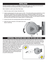
B.
Assembly
1.
Existing
Support
(Customer
Supplied)
IYiYfl:1~lI~lLef
FALLING
BOOM
can
cause
serious
personal
injury
and
equipment
damage.
Use
2-1/2
diameter,
Schedule
40
pipe
(wall
thickness
of
0.203)
as
support
pipe
for
12
booms.
Use
5
diameter,
Schedule
40
pipe
(wall
thickness
of
0.258)
as
support
pipe
for
16
booms.
a.
Uncrate
and
remove
all
packing
material
from
the
unit.
b.
Mount
pipe
post
(14)
to
the
desired
struc
ture.
c.
Proceed
to
Subsection
2.
Post
Support,
Steps
c-k.
TB-080 040
I!iTL~li~II~~Icf
FALLING
BOOM
can
cause
serious
personal
injury
and
equipment
damage.
Securely
mount
unit
to
a
structure
that
can
sup
port
the
weight
of
the
unit
when
the
boom
is
in
the
horizontal
position.
2.
Post
Support
(Optional)
a.
Uncrate
and
remove
all
packing
material
from
the
unit.
b.
Mount
post
support
(14)
to
the
desired
structure.
I~fl:l~Il~cf
FALLING
BOOM
can
cause
serious
personal
injury
and
equipment
damage.
S
Securely
mount
unit
to
a
structure
that
can
sup
port
the
weight
of
the
unit
when
the
boom
is
in
the
horizontal
position.
c.
Remove
yoke
pin
(1),
nut
(10),
washers
(9
&
17)
and
bolt
(18)
from
the
yoke
(3)
and
swivel
plates
(16).
WARNING
__________
RELEASE
OF SPRING
PRESSURE
WITHOUT
BOOM
AUACHED
can
cause
serious
personal
injury
and
equipment
damage.
Perform
installation
exactly
as
outlined
in
step-b
y
step
instructions
be/ow.
Do
not
remove
safety
collar
until
instructed
to
do
so.
Retain
safety
collar
for
future
disassembly
use.
d.
Place
bearing
(13)
on
top
of
post
(14)
and
in
sert
swivel
(8)
into
post
(14).
e.
Place
the
boom
base
plate
(19)
in
between
the
two
swivel
plates.
f.
Slide
washer
(17)
onto
bolt
(18)
and
insert
bolt
(18)
through
hole
(15).
Slide
washer
(9)
onto
bolt
(18)
and
install
nut
(10)
onto
bolt
(18).
Tighten
nut
(10);
then
back
off
nut
(10)
1/2
turn.
g.
Insert
pin
(1)
through
yoke
(3),
hole
(2),
and
install
cotter
pin
(4)
through
pin
(1).
h.
Connect
the
welding
gun
to
the
drive
assembly
as
instructed
in
the
Owners
Manual
for
the
desired
welding
gun.
i.
Grasp
bar
(20)
and
pull
boom
down
slightly.
The
boom
should
be
pulled
down
only
far
enough
to
remove
the
pressure
which
is
ap
plied
to
the
safety
collar
(11).
j.
Remove
and
retain
the
safety
collar
(11).
k.
The
boom
should
now
balance
in
any
posi
tion
from
horizontal
to
60
degrees
above
horizontal.
If
the
boom
does
not
balance
properly,
proceed
to
Section
3-10.
EXCESSIVE
FRICTION
can
damage
CAUTION
equipment.
Periodically
lubricate
swivel
to
prevent
wear.
Excessive
lubrication
is
not
required
or
recommended.
3.
Base
Support
(Optional)
1
.7
I0
.12
Figure
3-1.
Base
And
Boom
Assembly
Page
8

IMPORTANT
If
an
optional
base
support
was
pur
chased
with
the
unit,
mounting
ho/es
are
provided
for
fastening
the
base
support
to
the
floor.
IY,l~lI~Ic~
FALLING
BOOM
can
cause
serious
personal
injury
and
equipment
damage.
For
mounting
base
support
use,
as
a
minimum,
1/2
diameter,
S.
A.
E.
grade
5
bolts.
Use
equivalent
strength,
non-corrosive
bolts
if
unit
is
mounted
in
an
extremely
damp
environ-
ment.
a.
Uncrate
and
remove
all
packing
material
from
the
unit.
b.
Fasten
base
support
to
the
floor.
c.
Complete
Steps
c-k
in
Subsection
2.
Post
Support.
EXCESSIVE
FRICTION
can
damage
CAUTION
equipment.
Periodically
lubricate
swivel
to
prevent
wear.
Excessive
lubrication
is
not
required
or
recommended.
4.
Swingpak
Base
(Optional)
a.
Uncrate
and
remove
all
packing
material
from
the
Swingpak
base.
FALLING
BOOM
can
cause
serious
personal
injury
and
equipment
damage.
Mount
welding
power
source
on
Swingpak
base
before
mounting
Swingarc.
~NARNlNG
2.
Lift
the
wire
support
(7)
in
place
over
the
holes
in
the
swivel
base
(8).
3.
Insert
securing
screws
(5)
with
lock
washers
(6)
and
tighten.
3
-
4.
REINSTALLATION
OF
HUB
ASSEMBLY
(Figure
3-2)
-
If
it
should
become
necessary
to
replace
the
hub
assembly,
reinstall
the
new
hub
assembly
as
follows:
1.
Slide
the
following
items
onto
the
spindle
sup
port
shaft
(1)
in
order
given:
b.
Uncrate
and
remove
all
packing
material
from
the
Swingarc
unit.
c.
Complete
Steps
c
-
k
in
Subsection
2.
Post
CAUTION
Support.
EXCESSIVE
FRICTION
can
damage
equipment.
Periodically
lubricate
swivel
to
prevent
wear.
Excessive
lubrication
is
not
required
or
recommended.
3
-
2.
DRIVE
MOTOR
-
The
drive
motor
is
provided
with
a
vent
screw
which
must
be
removed
prior
to
the
operation
of
the
wire
feeder.
The
vent
screw
can
be
removed
through
the
hole
(21)
provided
in
the
motor
shroud
(see
Figure
3-1).
.MUIl.1~E
PRESSURE
IN
WIRE
DRIVE
MOTOR
GEAR
BOX
will
damage
motor.
Remove
vent
screw
prior
to
operation.
Warranty
is
void
if
the
vent
screw
is
not
removed
prior
to
operation.
3
-
3.
INSTALLATION
OF
WIRE
SUPPORT
(Figure
3-1)
1.
Remove
the
securing
screws
(5)
and
lock
washers
(6)
from
the
swivel
base
(8).
a.
Fiber
Washer
(2)
b.
Flat
Washer
(3)
c.
Hub
(4)
d.
Flat
Washer
(5)
e.
Fiber
Washer
(6)
f.
Keyed
Washer
(7)
g.
Spring
(8)
h.
Flat
Washer
(9)
2.
Rotate
hex
nut
(10)
onto
support
shaft
(1).
Hex
nut
should
be
rotated
only
until
a
slight
drag
is
felt
while
turning
hub
(4).
3.
Depress
the
two
spring
ba-led
stops
(11)
on
the
retaining
ring
(12)
and
slide
the
retaining
ring
(12)
into
proper
position
on
the
hub
(4).
Release
the
two
stops
(11).
3
-
5.
INSTALLATION
OF
WIRE
REEL
(Optional)
(Figure
3-3)
1.
Remove
the
retaining
ring
(5).
2.
Slide
the
wire
reel
(1)
onto
the
hub
(6).
Rotate
the
wire
reel
(1)
until
the
hub
guide
pin
(7)
is
seated
in
the
reel
(1).
3.
Depress
the
two
spring-loaded
stops
(4)
on
the
retaining
ring
(5)
and
slide
the
retaining
ring
(5)
56
9
10
11
12
TB-080
037
Figure
3-2.
Wire
Support
And
Hub
Assembly
OM-1516
Page9

into
proper
position
on
the
hub
(6).
Release
the
two
stops
(4).
3
-
6.
DRIVE
ROLL
AND
WIRE
GUIDE
INSTALLA
TION
(Figure
3-4)
-
Upon
initial
installation,
or
as
a
result
of
changes
in
wire
size
and
type,
it
is
necessary
to
install
the
required
drive
rolls
and
wire
guides.
IMPORTANT
______________
Base
selection
of
drive
rolls
upon
the
following
recommended
usages:
1.
V-Groove
rolls
for
hard
wire.
2.
U-Groove
rolls
for
soft
and
soft
shelled
cored
wires.
3.
U-Cog
rolls
for
extremely
soft
shelled
wires
(usually
hard
surfacing
typesi.
4.
Split
V-Knurled
rolls
for
hard
shelled
cored
wires
(seff-shielding
and
C02
shielded
types).
5.
Drive
roll
types
may
be
mixed
to
suit
particular
re
quirements
(example:
V-knurled
roll
in
combination
with
U-groove).
selected
the
appropriate
drIve
rolls
and
wire
proceed
to
the
following
installation
instruc
A.
Drive
Roll
Installation
(Figures
3-4
&
3-5)
1.
Loosen
pressure
adjustment
wing
nut
(item
2,
Figure
3-4)
and
pivot
it
free
of
the
cover.
2.
Pivot
gear
cover
(4)
away
to
expose
pressure
gear.
3.
Loosen
and
remove
the
three
securing
screws
(7
&
12)
on
each
gear
(5
&
9).
4.
For
one
piece
drive
rolls
(8
&
13):
slide
a
drive
roll
onto
the
drive
gear
(9)
and
pressure
gear
(5)
with
holes
aligned
and
secure
with
screws
(7
&
12).
For
split
drive
rolls
(6
&
10):
align
holes
on
each
pair
of
split
drive
rolls,
insert
a
securing
screw
(7
&
12)
and
slide
a
drive
roll
onto
a
drive
gear
(9)
and
pressure
gear
(5)
with
screw
in
line
with
one
of
the
threaded
holes.
Insert
remaining
screws
(7
&
12)
and
tighten.
IMPORTANT
______________
One-Piece
drive
rolls
(8
&
13)
are
of
the
double
usage
type.
When
the
grooves
become
Spilt
drive
rolls
(6
&
10)
are
of
the
double
usage
type.
When
the
knurled
groove
of
the
drive
rolls
becomes
worn,
the
spilt
halves
may
be
reversed
so
that
the
unus
ed
edges
will
now
provide
a
new
knurled
groove.
IMPORTANT:
To
ensure
proper
gripping
action
of
U-Cog
drive
rolls,
both
rolls
should
be
installed
showing
slots
on
the
side
or
both
should
show
the
side
without
slots.
Also,
it
is
necessary
to
ilne
up
the
blunted
teeth
on
the
pressure
gear
roll
directly
over
the
spaces
bet
ween
the
teeth
on
the
drive
gear
roll.
7
Figure
3-3.
Reel
Installation
worn,
reverse
each
drive
roll,
locating
the
unused
TB-080
038
groove
in
position
to
feed
the
wire.
Having
guides,
tions:
22
TB-080
030-A
Figure
3-4.
Drive
Rolls
Installation
Figure
3-5.
U-Cog
Drive
Rolls
Installation
TB-080
158
B.
Inlet
Wire
Guides
(Figure
3-4)
1.
For
.030
-
5/64
wire.
Page
10

a.
Insert
liner
(21)
into
inlet
wire
guide
(20)
and
secure
with
set
screw.
b.
Loosen
the
inlet
wire
guide
securing
screw
(3).
I
WA
I
~
1
V~
I
~
Wire
guides
should
be
installed
so
that
the
tip
of
the
guide
is
as
close
to
the
drive
roll
as
possible
without
touching.
c.
Insert
guide
assembly
into
drive
assembly.
Secure
by
tightening
screw
(3).
2.
For
3/32
-
1
/8
wire.
a.
Remove
anti-wear
guide(s)
(22)
from
inlet
wire
guide.
b.
Loosen
the
inlet
wire
guide
securing
screw
(3).
IMPORTANT
______________
Wire
guides
should
be
installed
so
that
the
tip
of
the
guide
is
as
close
to
the
drive
roll
as
possible
without
touching.
c.
Insert
the
inlet
wire
guide
(1)
into
drive
assembly
as
illustrated
in
Figure
3-4.
Secure
by
tightening
screw
(3).
d.
Install
anti-wear
guide(s)
(22)
onto
inlet
wire
guide
and
secure
with
setscrew.
IMPORTANT
______________
Drive
roll
alignment
has
been
factory
set,
but
if
readjustment
is
necessary
rotate
the
drive
gear
securing
bolt
(11)
thereby
moving
the
drive
roll
in
or
out
of
the
desired
position.
The
drive
roll
on
the
pressure
gear
will
locate
itseff
on
the
wire
when
the
gear
cover
is
replaced
and
the
gears
mesh
together.
The
wire
drive
housing
is
made
with
mounting
holes
of
sufficient
clearance
to
provide
adjustment
of
the
wire
guides
up
or
down
in
relation
to
the
drive
rolls.
This
ad
justment
has
been
factory
set,
but
if
readjustment
becomes
necessary,
loosen
mounting
bolts
(item
17,
Figure
3-4),
weld
terminal
nut
(18)
and
bolt,
located
behind
mounting
plate
(18).
Slide
the
wire
drive
hous
ing
upward
or
downward
until
the
wire
can
be
fed
straight
through
the
guides
while
seated
in
the
drive
roll
groove.
Tighten
mounting
bolts,
weld
terminal
bolt
and
nut.
3
-
7.
WATER
CONNECTIONS
(Optional)
OVERHEATING
of
Gas
Metal-Arc
Welding
(GMAW)
gun
can
damage
gun.
If
using
a
water
cooled
gun
and
recirculating
coolant
system,
do
not
make
connections
from
the
coolant
pump
to
water
valve;
instead,
make
connections
directly
from
the
coolant
system
to
gun
hoses.
A.
Installation
Of
Water
Hoses
When
a
water-cooled
gun
is
used,
route
the
water
hose
CAUTION
from
the
water
supply,
to
the
water
input
fitting
on
the
rear
of
the
control.
This
fitting
has
left-hand
threads.
Connect
the
water
out
hose
to
the
adapter
on
the
weld
cable
terminal
on
the
drive
assembly.
These
fittings
have
left-hand
threads.
Route
the
water
out
hose
to
a
proper
disposal
or
cooling
system.
Water
is
available
when
the
POWER
switch
is
placed
in
the
ON
position.
B.
Electrical
Reconnection
Of
Water
Solenoid
The
control
is
shipped
connected
to
supply
water
when
the
POWER
switch
is
in
the
ON
position.
The
water
solenoid
circuitry
can
be
modified
to
supply
water
when
the
gun
trigger
is
depressed.
1.
Shut
the
unit
down
and
disconnect
from
line
power.
I~~:l~lI~Ief
ELECTRIC
SHOCK
can
kill.
Do
not
touch
live
electrical
parts.
Disconnect
input
power
to
the
wire
feeder
or
employ
lockout/tagging
procedures
on
the
welding
power
source
before
internally
inspecting
or
servicing.
Lockout/tagging
procedures
consist
of
padlocking
line
disconnect
switch
in
open
position,
removing
fuses
from
fuse
box,
or
tagging
circuit
breaker
or
other
disconnecting
device.
Work
on
internal
parts
to
be
performed
by
qualified
per-
sons.
2.
Remove
control
box
wrapper.
3.
Locate
terminal
strip
iT
on
bottom
panel
of
con
trol.
4.
Move
lead
No.
35
from
terminal
A
on
terminal
strip
11
to
terminal
B.
5.
Replace
wrapper.
3
-
8.
WELDING
GUN
CONNECTIONS
A.
Outlet
Wire
Guide
(Figure
3-4)
IMPORTANT
the
gun
assembly.
The
outlet
guide
is
provided
as
part
of
1.
Loosen
the
gun/feeder
connector
securing
knob
(16).
IMPORTANT:
_________
Wire
guides
should
be
installed
so
that
the
tip
of
the
guide
is
as
close
to
the
drive
roll
as
possible
without
touching.
2.
Insert
the
connector
(14)
which
includes
the
in
stalled
outlet
guide
(15)
into
the
drive
assembly
opposite
the
inlet
wire
guide
as
illustrated
in
Figure
3-4.
3.
Tighten
the
gun/feeder
connector
securing
knob
(16).
OM-1516
Page
11

B.
Weld
Cable
(If
Applicable)
(Figure
3-4)
A
terminal
is
provided
on
the
lower
portion
of
the
drive
assembly
to
serve
as
a
junction
point
for
joining
together
the
weld
cables
from
the
welding
power
source
and
the
gun
(if
so
equipped).
Remove
weld
ter
minal
nut
(18),
lock
washer,
and
flat
washer;
slide
the
weld
cable
from
the
gun
onto
weld
terminal;
replace
flat
washer,
lock
washer,
nut
(18)
and
tighten.
C.
Shielding
Gas
The
shielding
gas
hose
from
the
gun
is
to
be
connected
to
the
gas
hose
which
protrudes
from
the
motor
end
of
the
boom.
II~I~.];lI.i~I~
An
integral
gas
input
fitting
is
provid
ed
on
the
weld
head
for
guns
utilizing
this
type
of
con
nection.
See
the
appropriate
welding
gun
Owners
Manual
for
instructions
on
making
this
connection.
If
the
hose
is
provided
with
a
fitting,
cut
the
fitting
off,
and
push
the
hose
onto
the
barbed
fitting
on
the
drive
assembly.
D.
Trigger
Control
The
plug
from
the
gun
trigger
is
to
be
inserted
fully
into
the
trigger
control
cable
and
the
locking
ring
rotated.
When
the
switch
connected
across
this
receptacle
is
closed,
the
contactor
in
the
welding
power
source
will
energize,
shielding
gas
will
flow
and
wire
will
begin
to
feed.
E.
Water
(If
Applicable)
Connect
the
water
input
hose
from
the
gun
to
the
water
output
hose
from
the
control.
Connect
the
water
return
hose
from
the
gun
to
the
adapter
at
the
weld
terminal
on
the
drive
assembly.
A
reducing
bushing
is
provided
to
accept
a
5/8-18
L.H.
fitting.
If
the
bushing
is
removed,
a
7/8-14
L.H.
fitting
can
be
accomodated.
3
-
9.
SHIELDING
GAS
CONNECTIONS
-
A
hose
is
supplied
with
the
unit
for
making
connections
from
the
shielding
gas
source
to
the
Shielding
Gas
input
fitting
at
the
rear
of
the
control.
These
fittings
have
right-hand
threads.
The
gas
hose
routed
through
the
boom
connects
to
the
Shielding
Gas
output
fitting
at
the
front of
the
control.
3-10.
BOOM
ADJUSTMENTS
(Figure
3-6)
A.
Weight
Lift
Adjustment
LYAYI~II~Ecr
FALLING
BOOM
can
cause
serious
personal
injury
and
equipment
damage.
Maintain
full
threads
on
adjustment
rod
through
the
yoke.
The
amount
of
weight
which
the
boom
can
retract
into
the
upright
position
when
released
can
be
varied
by
ad
justing
the
jam
nut
and
adjustment
rod
located
at
the
base
of
the
boom.
If
a
heavier
gun
is
installed
on
the
end
of
the
boom
thereby
making
it
necessary
to
increase
the
amount
of
weight
that
the
boom
can
lift,
loosen
the
jam
r~ut
and
rotate
the
adjustment
rod
so
that
the
adjust
ment
rod
threads
into
the
yoke.
When
the
proper
ad
justment
is
obtained,
tighten
the
jam
nut
against
the
base
of
the
yoke.
If
a
lighter
gun
is
used
with
the
Sw-
ingarc,
rotate
the
adjustment
rod
so
that
the
adjustment
rod
threads
out
of
the
yoke.
B.
Locking
Knob
By
rotating
the
Locking
Knob
in
a
clockwise
direction,
the
boom
may
be
held
in
any
desired
position.
Rotating
the
Locking
Knob
in
a
counterclockwise
direction
will
permit
the
boom
to
free
travel.
Changing
the
position
of
the
Locking
Knob
to
the
other
threaded
holes
provided
along
the
side
of
the
swivel
plate,
limits
the
lift
of
the
boom
to
50
degrees
or
40
degrees
respectively
during
free
travel.
3-11.
WIRE
PULLEY
(Figure
3-1)
-
Position
of
the
wire
guide
pulley
is
adjusted
by
placing
the
axle
through
the
holes
in
the
support
arms.
The
boom
is
shipped
with
wire
guide
pulley
positioned
through
upper
set
of
holes
for
running
wire
of
smaller
diameter.
If
excessive
wear
is
noticed
in
the
inlet
guide
and/or
guide
tube,
or
if
the
boom
is
to
be
used
for
running
wire
of
larger
diameter,
position
wire
guide
pulley
through
lower
set
of
holes.
Jam
Nut
Adjustment
Rod
TB-072
727
3-12.
MOTOR
CONTROL
CONNECTIONS
(Figure
3-7)
-
A
receptacle
is
provided
for
connecting
the
motor
control
plug
to
the
control.
Align
keyways
and
in
sert
the
plug
from
the
control
end
of
the
boom
into
the
receptacle
and
rotate
the
plug
threaded
collar
clockwise
as
far
as
possible.
TA-072
726
3-13.
GUN
TRIGGER
CONNECTION
(Figure
4-1)
-
A
TRIGGER
receptacle
is
provided
for
making
gun
trigger
control
connections.
The
gun
trigger
control
cables
extend
out
of
the
control
end
of
the
boom.
Insert
the
gun
trigger
control
plug
into
the
TRIGGER
recep
tacle
and
rotate
threaded
collar
clockwise.
-Yoke
Figure
3-6.
Boom
Adjustments
Figure
3-7.
Rear
Panel
Connections
Page
12

3-14.
WELD
CABLE
CONNECTION
-
A
weld
cable
extends
out
of
the
wire
support
end
of
the
boom
for
making
secondary
connections
to
the
welding
power
source.
The
end
of
the
weld
cable
is
equipped
with
a
terminal
for
a
1/2
stud.
3-15.
REMOTE
CONTROL
CONNECTIONS
(Figure
4-1)
-
A
receptacle
is
provided
for
connecting
a
remote
control
to
the
unit.
Align
keyways
and
insert
plug
from
the
remote
control
into
the
receptacle
and
rotate
the
threaded
collar
clockwise
as
far
as
possible.
3-16.
INSTALLATION
OF
SPOOL-TYPE
WIRE
(Figure
3-2)
1.
Remove
the
retaining
ring
(12).
2.
Slide
the
spool
of
wire
onto
the
hub
(4)
so
that
the
wire
will
feed
off
the
top
of
the
spool.
The
spool
turns
in
a
clockwise
direction.
3.
Rotate
the
spool
until
the
hole
in
the
spool
aligns
with
the
pin
in
the
hub
(4).
Slide
the
spool
onto
the
hub
until
it
seats
against
the
back
flange
of
the
hub.
4.
Depress
the
two
spring-loaded
stops
(11)
on
the
retaining
ring
(12)
and
slide
the
retaining
ring
(12)
into
proper
position
on
the
hub
(4).
Release
the
two
stops
(11).
3-17.
INSTALLATION
OF
REEL-TYPE
WIRE
(Figure
3-3)
1.
Loosen
the
four
wing
nuts
(3)
on
the
fingers
(2)
of
the
wire
reel
(1).
2.
Pull
the
four
fingers
(2)
out
until
they
can
be
rotated
toward
the
center
of
the
reel
(1).
3.
Install
the
wire
onto
the
reel
(1)
over
the
four
fingers
(2).
Ensure
that
the
wire
feeds
off
the
top
of
the
reel
(1).
The
reel
(1)
turns
in
a
clockwise
direction.
4.
Rotate
the
four
fingers
(2)
back
to
their
proper
position.
Tighten
the
four
wing
nuts
(3).
3-18.
ADJUSTMENT
OF
HUB
TENSION
(Figure
3-2)
-
Check
the
hub
tension
by
slowly
pulling
the
wire
toward
the
feed
roll.
The
wire
should
unwind
freely,
but
the
hub
tension
should
be
sufficient
to
keep
the
wire
taut
and
prevent
backlash
when
the
wire
feeding
ceases.
If
adjustment
is
required,
loosen
or
tighten
the
hex
nut
(10)
on
the
end
of
the
spindle
support
shaft
(1)
accordingly.
3-19.
115
VOLTS/CONTACTOR
CONNECTIONS
(Figure
3-7)
-
A
10
ft.
cable
is
provided
for
115
volts
ac
power
and
contactor
control
connections
between
con
trol
and
welding
power
source.
Route
the
cable
through
the
handles
on
the
wire
feeder
base
and
ensure
that
it
will
not
interfere
with
wire
feed.
Align
keyways
and
in
sert
the
plug
into
receptacle
on
the
control
and
rotate
the
threaded
collar
clockwise
as
far
as
possible.
Insert
the
115
volts
power
plug
into
the
115
volts
ac
recep
tacle
on
the
welding
power
source
and
rotate
clockwise
to
lock
in
place.
Insert
contactor
control
plug
into
the
contactor
control
receptacle
on
the
welding
power
source
and
rotate
clockwise
to
lock
in
place.
t~.U1I.1~~
IMPROPER
VOLTAGE
APPLIED
TO
WELDING
POWER
SOURCE
CONTACTOR
can
damage
wire
feeder
and
welding
power
source.
S
Ensure
we/ding
power
source
contactor
control
circuitry
requires
external
supply
of
115
vac
for
con
tactor
control.
Wire
feeder
supplies
115
volts
ac
to
the
welding
power
source
for
contactor
control.
SECTION
4
-
FUNCTION
OF
CONTROLS
Figure
4-1.
Control
Components
operational
condition,
ready
to
feed
wire
and
permit
shielding
gas
to
flow.
Placing
the
POWER
switch
in
the
OFF
position
will
shut
the
wire
feeder
down.
4
-
2.
REMOTE
CONTROL
RECEPTACLE
AND
SWITCH
(Figure
4-1)
-
The
remr~te
control
receptacle
is
provided
for
use
in
conjunction
with
certain
optional
controls.
If
a
remote
control
is
to
be
used,
make
con
nections
as
instructed
in
Section
3-15
and
place
the
Remote
Control
switch
in
the
REMOTE
position.
If
a
remote
control
is
not
to
be
used,
place
the
Remote
Con
trol
switch
in
the
STANDARD
position.
4
-
3.
PURGE
BUTTON
(Figure
4-1)
-
The
PURGE
button
is
a
momentary
contact
switch.
This
switch
TA-o72
725
energizes
the
gas
solenoid
and
purges
the
shielding
gas
line
of
the
gun.
The
PURGE
button
also
allows
the
shielding
gas
regulator
to
be
adjusted
without
energiz~
ing
the
welding
circuit.
4
-
4.
JOG
BUTTON
(Figure
4-1)
-
The
JOG
button
is
a
momentary
contact
switch.
When
actuated
it
corn-
Retract/Feed
Fuse
Switch
Button
Control
Switch
Receptacle
4
-
1.
POWER
SWITCH
(Figure
4-1)
-
Placing
the
POWER
switch
on
the
control
in
the
ON
position
will
apply
115
volts
ac
to
the
unit
and
thereby
place
it
in
an
OM-1516
Page
13

pletes
the
circuit
to
the
motor
without
having
to
depress
the
gun
trigger
switch.
This
switch
permits
jogging
of
the
wire
at
the
WIRE
SPEED
control
setting,
without
energizing
the
welding
circuit
or
the
shielding
gas
valve.
CAUTION
_________
CHANGING
RETRACT
FEED
SWITCH
POSITION
while
welding
can
damage
switch
and
wire
drive
motor.
Do
not
change
position
of
switch
while
the
wire
drive
motor
is
running.
4
-
5.
WIRE
SPEED
CONTROL
(Figure
4-1)
-
The
WIRE
SPEED
control
provides
a
means
of
determining
the
rate
at
which
welding
wire
will
be
fed
into
the
weld.
Rotating
the
WELD
SPEED
control
clockwise
increases
the
rate
of
the
wire
feed.
4
-
6.
START
SWITCH
(Figure
4-1)
-
The
START
switch
provides
the
capability
of
being
able
to
select
either
a
slow
wire
feed
speed
for
1/2
second
at
the
beginning
of
wire
feed,
or
the
wire
feed
speed
at
the
rate
set
on
the
WIRE
SPEED
control.
The
SLOW
posi
tion
of
the
START
switch
provides
the
1/2
second
of
slow
wire
feed,
and
the
FAST
position
provides
wire
feed
at
the
rate
set
on
the
WIRE
SPEED
control.
4
-
7.
RETRACT-FEED
SWITCH
(Figure
4-1)
-
The
RETRACT-FEED
switch
determines
whether
the
wire
feeds
out
of
the
gun
or
retracts
back
into
the
gun
when
the
gun
switch
is
closed.
The
RETRACT
position
causes
the
wire
to
go
back
into
the
gun,
and
the
FEED
position
causes
the
wire
to
feed
Out
of
the
gun.
The
switch
should
be
in
the
FEED
position
for
normal
operation.
4
-
8.
RESET
CIRCUIT
BREAKER
(Figure
4-1)
-
A
circuit
breaker
provides
protection
to
the
feeder
motor.
In
the
event
the
motor
should
be
placed
in
an
overload
condition,
the
breaker
would
trip
and
suspend
all
out
put.
Should
this
breaker
trip,
the
RESET
button
would
have
to
be
manually
depressed
in
order
to reset
the
cir
cuit
breaker.
4
-
9.
BURNBACK
CONTROL
(Optional)
-
The
burnback
circuitry
in
this
control
provides
a
means
of
keeping
the
welding
wire
from
sticking
to
the
workpiece
after
the
gun
switch
is
released.
The
burnback
capabili
ty
in
this
wire
feeder
keeps
weld
current
present
on
the
welding
wire
from
0
to
15
cycles
after
the
wire
has
stop
ped
feeding,
depending
upon
the
setting
of
the
BURN-
BACK
control.
This
delay
action
permits
the
welding
wire
to
burn
back
to
a
point
where
it
neither
sticks
to
the
workpiece
nor
the
contact
tube.
If
the
welding
wire
sticks
to
the
contact
tube,
rotate
the
BURNBACK
con
trol
counterclockwise.
If
the
welding
wire
sticks
to
the
workpiece,
rotate
the
BURNBACK
control
clockwise.
SECTION
5
-
SEQUENCE
OF
OPERATION
5
-
1.
WELDING
WIRE
THREADING
WARNING
__________
ELECTRIC
SHOCK
can
kill.
Do
not
energize
we/ding
power
source
or
wire
feeder
until
instructed
to
do
so.
Do
not
touch
live
electrical
parts.
Welding
wire
and
all
metal
parts
in
contact
with
it
carry
weld
current
when
the
welding
power
source
contactor
is
energized.
ts~tUII]~
WELDING
WIRE
can
cause
puncture
wounds;
HOT
SURFACES
can
burn
skin.
Do
not
activate
gun
trigger
until
instructed
to
do
so.
Do
not
point
gun
towards
any
part
of
the
body
or
other
personnel
when
threading
we/ding
wire.
Allow
gun
to
cool
before
touching.
1.
Install
the
wire
(reel-type
or
spool-type)
as
in
structed
in
Section
3-16
or
3-17.
2.
Cut
off
any
portion
of
the
free
end
of
the
wire
which
is
not
straight.
Ensure
that
the
cut
end
is
free
from
rough
surfaces
to
permit
proper
feeding.
3.
Route
the
wire
through
the
wire
guide
tube
on
the
side
of
the
boom,
over
the
wire
pulley,
and
to
the
drive
assembly.
5.
Feed
the
wire
through
the
inlet
wire
guide,
past
the
drive
rolls,
and
on
into
the
outlet
wire
guide.
Feed
approximately
4
inches
of
wire
into
the
outlet
wire
guide.
IMPORTANT:
If
when
the
gear
cover
is
closed
the
U-Cog
drive
rolls
are
not
aligned
properly
(see
Section
3-6),
pivot
the
gear
cover
away
from
the
drive
gear
and
rotate
the
pressure
gear
one
tooth.
6.
Pivot
the
gear
cover
closed
making
sure
the
teeth
on
the
pressure
gear
mesh
with
the
teeth
on
the
drive
gear.
The
welding
wire
must
also
be
in
the
grooves
of
the
drive
rolls.
7.
Pivot
the
pressure
adjustment
wing
nut
until
the
washer
on
the
pressure
adjustment
is
seated
on
top
of
the
gear
cover.
8.
Turn
the
pressure
adjustment
wing
nut
in
a
clockwise
direction
until
the
drive
rolls
are
tight
against
the
welding
wire.
Do
not
overtighten.
Further
adjustment
to
attain
desired
clamping
pressure
can
be
made
after
the
welding
power
source
and
the
wire
feeder
are
put
into
opera
tion.
9.
Draw
the
gun
cable
out
straight.
4.
Loosen
the
wing
nut
on
the
drive
roll
pressure
adjustment,
pivot
the
pressure
adjustment
free
of
the
cover,
and
pivot
the
pressure
gear
assembly
away
until
it
is
in
an
open
position.
10.
Energize
the
welding
power
source.
11.
Place
the
control
POWER
switch
in
the
ON
posi
tion.
Page
14

12.
Depress
the
JOG
switch.
This
will
run
the
welding
wire
through
the
gun
without
placing
weld
current
on
the
welding
wire.
Release
the
JOG
switch
when
the
welding
wire
extends
ap
proximately
one
inch
Out
of
the
gun
tip.
I~YI~1:I~II~cf
ARC
RAYS,
SPARKS,
AND
HOT
SURFACES
can
burn
eyes
and
skin;
NOISE
can
damage
hearing.
Wear
correct
eye,
ear,
and
body
protection.
FUMES
AND
GASES
can
seriously
harm
your
health.
Use
enough
ventilation
to
keep
fumes
and
gases
from
the
breathing
zone.
See
Section
1
-
Safety
Rules
For
Operation
Of
Arc
Welding
Power
Sources
for
basic
welding
safety
infor
mation.
5
-2.
GAS
METAL-ARC
WELDING
(GMAW)
1.
Make
all
necessary
connections
as
instructed
in
Section
3.
2.
Place
the
Remote
Control
switch
in
the
desired
position.
3.
Place
the
START
switch
in
the
desired
position.
4.
Place
the
RETRACT-FEED
switch
in
the
desired
position.
7.
Rotate
the
WIRE
SPEED
control
to
the
desired
setting.
8.
Turn
on
the
shielding
gas
at
the
source.
9.
Depress
the
PURGE
button
for
one
minute.
10.
Hold
the
tip
of
the
gun
approximately
1/2
inch
from
the
workpiece.
11.
Depress
the
trigger
on
the
gun
handle.
Gas
will
start
to
flow
and
wire
will
start
to
feed
if
drive
roll
pressure
is
properly
adjusted
to
prevent
slippage.
If
wire
slippage
is
noticed,
tighten
the
drive
roll
pressure
adjustment
wing
nut
1/2
turn
clockwise.
Repeat
until
slippage
stops.
Do
not
overtighten
wing
nut.
WARNING
_________
ELECTRIC
SHOCK
can
kill.
Do
not
touch
welding
wire
or
any
metal
part
in
contact
with
it
while
we/ding.
Do
not
touch
live
electrical
parts.
Welding
wire
and
all
metal
parts
in
contact
with
it
carry
weld
current
when
the
welding
power
source
contactor
is
energized.
5
-3.
SHUTFING
DOWN
1.
Turn
off
the
shielding
gas
at
the
source.
2.
Place
the
POWER
switch
in
the
OFF
position.
5.
Energize
the
welding
power
source.
6.
Place
the
POWER
switch
in
the
ON
position.
3.
Turn
off
all
associated
equipment.
WARNING
_________
Gases
can
harm
health
or
kill.
Shut
off
gas
supply
when
not
in
use.
SECTION
6
-
MAINTENANCE
6
-
1.
INSPECTION
AND
UPKEEP
-
Usage
and
shop
conditions
will
determine
the
frequency
and
type
of
maintenance.
Inspect
equipment
as
follows:
6.
Blow
Out
the
gun
wire
guide
liner
with
compress
ed
air
when
changing
wire.
This
will
remove
any
metal
chips
and
dirt
that
may
have
accumulated.
WARNING
__________
ELECTRIC
SHOCK
can
kill;
WELDING
WIRE
can
cause
puncture
wounds;
HOT
SURFACES
can
burn
skin.
Disconnect
unit
from
input
power
before
internal
ly
inspecting
or
servicing.
Allow
gun
and
unit
to
cool
before
touching.
Do
not
activate
gun
trigger
while
performing
maintenance
on
gun.
1.
Make
sure
welding
power
source
is
shut
down.
2.
Inspect
gun
for
broken
areas,
cracks
and
loose
parts:
tighten,
repair,
and
replace
as
required.
3.
Carefully
remove
any
weld
spatter
or
foreign
matter
which
may
accumulate
around
the
nozzle
orifice.
Use
a
hardwood
stick,
never
a
metal
tool.
4.
Repair
or
replace,
as
required,
all
hose
and
cable;
give
particular
attention
to
frayed
and
cracked
in
sulation
and
areas
where
it
enters
equipment.
5.
Remove
grease
and
grime
from
components;
moisture
from
electrical
parts
and
cable.
IMPORTANT:
_______
Periodically
inspect
the
labels
on
the
unit
for
legibility.
All
labels
must
be
maintained
in
a
clearly
readable
state
and
replaced
when
necessary.
See
Parts
List
for
part
number
of
labels.
6
-
2.
CLEANING
OF
DRIVE
ROLLS
-
Occasionally
it
will
become
necessary
to
clean
t
e
wire
groove
on
the
drive
rolls.
This
cleaning
operation
can
be
performed
with
a
wire
brush.
To
clean
the
wire
grooves
it
will
be
necessary
to
discon
nect
unit
from
line
power
before
removing
the
drive
roll(s)
(see
Section
3-6
for
removal
and
installation
in
structions).
IMPORTANT
______________
Failure
to
properly
maintain
the
drive
rolls
can
result
in
a
build-up
of
wire
particles
which
will
decrease
the
efficiency
of
the
wire
feeding
operation.
6
-
3.
FUSE
(Figure
4-1)
-
The
control
is
protected
from
damage
due
to
an
internal
short
or
excessive
overload
by
fuse
Fl.
Should
Fl
open,
the
control
would
be
completely
inoperative.
OM-1516
Page
15

6
-
4.
BRUSH
INSPECTION
&
REPLACEMENT
(Figures
6-1
&
6-2)
WARNING
__________
ELECTRIC
SHOCK
can
kill.
Do
not
touch
live
electrical
parts.
Disconnect
input
power
to
the wire
feeder
or
employ
lockout/tagging
procedures
on
welding
power
source
before
internally
inspecting
or
ser
vicing.
Lockout/tagging
procedures
consist
of
padlocking
line
disconnect
switch
in
open
position,
removing
fuses
from
fuse
box,
or
tagging
circuit
breaker
or
other
disconnecting
device.
Work
on
internal
parts
to
be
performed
by
qualified
per
sons.
1.
Shut
unit
and
associated
equipment
off.
2.
Open
brush
cap
by
sliding
screwdriver
under
catch
and
lifting.
Remove
brush
cap.
3.
Grasp
spring
retaining
bracket
with
long-nose
pliers.
4.
Push
spring
retaining
bracket
in
lightly
and
move
towards
brush~
This
should
release
the
spring
assembly
and
it
can
be
removed.
6.
If
replacement
is
necessary
(brushes
are
less
than
1/4
in
length)
disconnect
the
brush
pigtail
from
the
brush
box
tab
and
remove
brush.
7.
Connect
new
brush
pigtail
to
brush
box
tab.
8.
Route
pigtail
through
slot
in
brush
box.
Ensure
that
the
pigtail
will
not
come
into
contact
with
a
metal
surface.
9.
Insert
brush
into
brush
box.
Ensure
that
the
low
end
of
the
bevel
on
the
top
of
the
brush
is
towards
the
spring.
10.
Using
long-nose
pliers
insert
spring
assembly
beside
brush
sliding
the
spring
retaining
bracket
along
the
brush
box
wall.
The
spring
retaining
bracket
hooks
on
the
brush
box
wall
as
il
lustrated
in
Figure
6-2.
11.
If
the
spring
retaining
bracket
is
in
place,
it
will
be
against
the
brush
box
wall
when
the
pliers
are
released.
12.
Ensure
that
the
spring
is
in
the
proper
position
as
illustrated
in
Figure
6-1.
13.
Replace
and
latch
the
brush
cap.
Brush
Pigtail
Figure
6-1.
View
Of
Spring
Assembly
And
Brush
When
Brush
Cap
Is
Opened
14.
Reconnect
power
to
all
equipment
and
resume
operation.
Figure
6-2.
View
Of
Spring
Assembly
And
Brush
From
Armature
End
Of
Motor
SECTION
7
-
TROUBLESHOOTING
WARNING
__________
ELECTRIC
SHOCK
can
kill.
Do
not
touch
live
electrical
parts.
Disconnect
unit
from
input
power
before
internal
ly
inspecting
or
servicing.
Troubleshooting
of
internal
parts
to
be
performed
only
by
qualified
persons.
The
following
chart
is
designed
to
diagnose
and
provide
remedies
for
some
of
the
troubles
that
may
develop
in
this
unit.
It
is
assumed
that
proper
installation
has
been
made,
ac
cording
to
Section
3
of
this
manual,
and
that
the
unit
his
been
functioning
properly
until
this
trouble
developed.
Use
this
chart
in
conjunction
with
the
circuit
diagram
while
performing
troubleshooting
procedures.
If
the
Page
16
trouble
is
not
remedied
after
peiorming
these
pro
cedures,
the
nearest
Factory
Authorized
Service
Sta
tion
should
be
contacted.
In
all
cases
of
equipment
malfunction,
the
manufacturers
recommendations
should
be
strictly
followed.
CAUTION
_________
DISASSEMBLY
OF
MOTOR
FIELD
MAGNETS
can
result
in
personal
injury
or
equip
ment
damage.
Limit
wire
drive
motor
repairs
to
brush
replace
ment.
The
field
magnets
are
very
strong.
If
disassembly
is
at
tempted,
injury
to
fingers
and
hands
may
result
from
a
magnet
being
drawn
back
into
the
motor.
The
field
magnets
are
matched
sets
and
operation
may
be
af
fected
if
the
magnets
are
tampered
with.
Warranty
is
void
if
the
motor
is
tampered
with.
5.
Pull
brush
out
using
brush
pigtail.
Spring
Spring
Bracket
Brush
Box
Brush
NOTE:
Spring
assembly
hooks
TA-046
226
here.
1/36