Page is loading ...

April
1979
FORM:
OM-1522
FLE
COPY
RETURN
TO
FOLDER
Effective
With
Serial
No.
HK270136
MODEL
SWINGARC
DIGITAL
-
1
12
SWINGARC
DIGITAL
-
1
16
OWNERS
MANUAL
HilliER
MILLER
ELECTRIC
MFG.
CO.
718
S.
BOUNDS
ST.
P.O.
Box
1079
APPLETON.
WI
54912
USA
ADDITIONAL
COPY
PRICE
70
CENTS
NWSA
CODE
NO. 4579
PRINTED
IN
U.S.A

LIMITED
WARRANTY
EFFECTIVE:
JANUARY
1,1979
This
warranty
supersedes
all
previous
MILLER
warranties
and
is
cx-
S
clusive
with
no
other
guarantees
or
warranties
expressed
or
implied.
LIMITED
WARRANTYSubject
to
the
terms
and
conditions
As
a
matter
of
general
policy
only,
Miller
may
honor
claims
hereof,
Miller
Electric
Mfg.
Co.,
Appleton,
Wisconsin
warrants
to
submitted
by
the
original
user
within
the
foregoing
periods.
its
Distributor/Dealer
that
all
new
and
unused
Equipment
furnished
In
the
case
of
Millers
breach
of
warranty
or
any
other
duty
by
Miller
is
free
from
defect
in
workmanship
and
material
as
of
the
time
and
place
of
delivery
by
Miller.
No
warranty
is
made
by
Miller
with
respect
to
the
quality
of
any
goods,
the
exclusive
remedies
therefor
shall
be,
at
Millers
option,
(1)
repair
or
(2)
replacement
or,
with
respect
to
engines,
trade
accessories
or
other
items
manu-
where
authorized
in
writing
by
Miller
in
appropriate
cases,
(3)
the
factured
by
others.
Such
engines,
trade
accessories
and
other
reasonable
cost
of
repair
or
replacement
at
an
authorized
Miller
ser
items
are
sold
subject
to
the
warranties
of
their
respective
manu
facturers,
if
any.
At
the
present
time,
the
manufacturers
warranty
on
vice
station
or
(4)
payment
of
or
credit
for
the
purchase
price
(less
the
Mag-Diesel
engine
on
DEL-200
is
limited
to
six
months
and
on
reasonable
depreciation
based
upon
actual
use)
upon
return
of
the
all
other
engines
to
one
year
goods
at
Customers
risk
and
expense.
Upon
receipt
of
notice
of
apparent
defect
or
failure,
Miller
shall
instruct
the
claimant
on
the
Except
as
specified
below,
Millers
warranty
does
not
apply
to
warranty
claim
procedures
to
be
followed.
components
having
normal
useful
life
of
less
than
one
(I)
year,
such
ANY
EXPRESS
WARRANTY
NOT
PROVIDED
HEREIN
AND
as
spot
welder
tips,
relay
and
contactor
points,
MILLERMATIC
parts
ANY
IMPLIED
WARRANTY
GUARANTY
OR
REPRESENTA
~
that
come
in
contact
with
the
welding
wire
including
nozzles
and
TION
AS
TO
PERFORMANCE,
AND
ANY
REMEDY
FOR
nozzle
insulators
where
failure
does
not
result
from
defect
in
BREACH
OF
CONTRACT
WHICH,
BUT
FOR
THIS
PROVISION,
workmanship
or
material.
MIGHT
ARISE
BY
IMPLICATION,
OPERATION
OF
LAW,
CUS
TOM
OF
TRADE
OR
COURSE
OF
DEALING
INCLUDING
ANY
Miller
shall
be
required
to
honor
warranty
claims
on
warranted
IMPLIED
WARRANTY
OF
MERCHANTABILITY
OROF
FITNESS
Equipment
in
the
event
of
failure
resulting
from
a
defect
within
(he
FOR
PARTICULAR
PURPOSE,
WITH
RESPECT
TO
ANY
AND
following
periods
from
the
date
of
delivery
of
Equipment
to
the
ALL
EQUIPMENT
FURNISHED
BY
MILLER
IS
EXCLUDED
original
user:
AND
DISCLAIMED
BY
MILLER.
I.
Arc
welders,
power
sources
and
components
.
.
. .
1
year
EXCEPT
AS
EXPRESSLY
PROVIDED
BY
MILLER
IN
WRIT-
)
2.
Onginal
main
power
rectifiers
3
years
ING
MILLER
PRODUCTS
ARE
INTENDED
FOR
ULTIMATE
(labor
-
1
year
only)
PURCHASE
BY
COMMERCIAL/INDUSTRIAL
USERS
AND
FOR
3.
All
welding
guns
and
feeder/guns
90
days
OPERATION
BY
PERSONS
TRAINED
AND
EXPERIENCED
IN
4.
All
other
Millermatic
Feeders
1
year
THE
USE
AND
MAINTENANCE
OF
WELDING
EQUIPMENT
AND
5.
Replacement
or
repair
parts,
exclusive
of
labor.
.
60
days
NOT
FOR
CONSUMERS
OR
CONSUMER
USE.
MILLER
WAR-
)
6.
Batteries
6
months
RANTIES
DO
NOT
EXTEND
TO,
AND
NO
RESELLER
IS
provided
that
Miller
is
notified
in
writing
within
thirty
(30)
days
of
AUTHORIZED
TO
EXTEND
MILLERS
WARRANTIES
TO,
the
date
of
such
failure.
ANY
CONSUMER.
.~
J~
.
.-.....
-
.
.....-~

CAUTION
C
ERRATA
SHEET
After
this
manual
was
printed,
refinements
in
equipment
design
occurred.
This
sheet
lists
exceptions
to
data
appearing
later
in
this
manual.
Effective
With
Serial
No.
HK270154
Ii
l~
Delete
all
reference
to
Switch
Control
receptacle
in
this
manual
and
replace
with
TRIGGER
receptacle.
AMENDMENT
TO
SECTION
6
TROUBLESHOOTING
Add
CAUTION
block
after
Troubleshooting
Chart
Wire
drive
motor
repairs
should
be
limited
to
brush
replacement.
Attempting
further
repairs
may
result
in
personal
injury
in
addition
to
motor
damage.
Warranty
is
void
if
the
motor
is
tampered
with.
For
further
repair
and
replacement
in
formation
contact
the
Factory
Service
Department.
See
Page
B
for
Circuit
Diagram.
OM-1
622
Page
A

GAS
SOLENOID
WATER
SOLENOID
(OPTIONAL)
RC3
P)53
C-047
809
ISO
>
2
S
a.
m
Co
C
-
S
9)
C-)
~~1
C,
C
I:
0
a)
Co
2
Circuit
Diagram
No.
C-047
809
S
Figure
6-1.
Circuit
Diagram
For
Models
Effective
With
Serial
No.
HK210154
And
Following
S.

Item
Dia.
No.
Mkgs.
A50-53
C50
C51
C52,61
C53,62
CM
C55,
66-77
C56
C57
C60
C63,64
C65
CR50
D50-54,
56-58.
D55
1C50
Q50,53
Q51
Q52
R50
R51
.53-57,63,
74,75,81,82,
84,89
R52
R58,62,65,
66,71,72,
76,77,90
R59
R60,87,88
R64,67
R68,80
R70
R73,83
R78
R79
R85
R86
T50
VR5O
VR51
RC7
Part
No.
Listed
Replaced
With
In
Parts
List
Part
No
048
837
603
106
047
311
047
312
047
636
079
535
048
283
079
535
047
227
009
159
039
482
031
699
073
739
035
833
005
023
031
643
073
549
035
835
035
561
031
694
031
721
081
797
080
910
081
800
037
200
037
824
039
355
030
839
039
335
039
331
035
886
048
015
039
328
039
108
039
106
030
937
030
090
036
143
081
799
047
272
047
123
047637
079
534
048 282
079
534
047
224
047
170
047
171
023 562
Description
HOSE
ASSEMBLY,
gas
HOSE,
neoprene
-
braided
No.
1
(order
by
foot)
CORD,
motor
l5ft
CORD,
motor
19
ft.
(consisting
of)
HOUSING
PLUG
&
PINS
.TERMINAL,malesizel6
18-l4wire
RECEPTACLE,
w/pins
(consisting
of)
TERMINAL,
male
1
pin
CIRCUIT
CARD
ASSEMBLY,
motor
speed
(consisting
of)
AMPLIFIER,
operational
32
volts
dc
CAPACITOR,
electrolytic
100
uf
35
volts
dc..
CAPACITOR,
mylar
0.0022
uf
200
volts
dc
CAPACITOR,
ceramic
0.1
uf
50
volts
CAPACITOR,
mylar
0.033
uf
100
volts
dc.
CAPACITOR,
tantalum
2.2
uf
20
volts
CAPACITOR,
ceramic
0.01
uf500voltsdc
CAPACITOR,
mylar0.Ol5uf200volts
CAPACITOR,
electrolytic
4.7
uf
35
volts
CAPACITOR,
mylar
4
uf
200
volts
CAPACITOR,
mylar
0.47
uf
200
volts
dc
CAPACITOR,
mylar
0.22
uf
200
volts
dc
RELAY,
enclosed
24
volts
ac
4PDT
Quantity
Model
12
I
16
1
1
loft,
lOft.
1
1
1
6
1
4
13
13
1
1
9
9
8
056420
13
603
106
29
049869
29
048619
30
PLG7
073
517
78
RC1
081
905
83
049016
1
6
1
4
1
4
1
1
2
2
1
13
1
1
1
2
1
1
8
1
1
2
1
1
1
1
4
1
1
2
2
1
13
1
1
1
2
1
1
8
1
1
2
1
1
1
026
202
.
DIODE,
rectifier
1
amp
400
volts
straight
polarity
DIODE,
zener
l5volts5watt
INTEGRATED
CIRCUIT,
converter
TRANSISTOR,
200
MA
40
volts
NPN
THYRISTOR,
SCR
7.4
amp
200
volts
TRANSISTOR,
unijunction
15MA
40
volts
RESISTOR,
WW
fixed
5
watt
220
ohm
84
94
117
035
827
.
RESISTOR,
carbon
film
0.25
watt
10K
ohm...
052
138
.
RESISTOR,
carbon
film
0.25
watt
20K
ohm...
035
884
.
RESISTOR,
carbon
film
0.25
watt
lOOK
ohm..
030
007
.
POTENTIOMETER,
cermet
trimmer
15
turn
0.75
watt
50K
ohm
RESISTOR,
carbon
film
0.25
watt
47K
ohm...
RESISTOR,
carbon
film
0.25
watt
4700
ohm..
RESISTOR,
carbon
film
0.25
watt
22K
ohm...
RESISTOR,
carbon
film
0.25
watt
10
meg
ohm
RESISTOR,
carbon
film
0.25
watt
1500
ohm..
RESISTOR,
carbon
film
0.25
watt
82K
ohm...
RESISTOR,
carbon
film
0.25watt470
ohm
RESISTOR,
carbon
0.5
watt
10
ohm
RESISTOR,
carbon
0.5watt47
ohm
TRANSFORMER,
pulse
control
REGULATOR,
voltage
8
volts
3
terminals
REGULATOR,
voltage
l2voIts3
terminals
STAND-OFF,
No.
4-40
x
2-5/8
(consisting
of)
HOUSING
RECEPTACLE
&
SOCKETS
..TERMINAL,
female
1
socket
RECEPTACLE,
w/socket
(consisting
of)
TERMINAL,
female
1
socket
KNOB,
plastic
TUBING,
neoprene
3/8
ID
x
0.093
wall
x
12.
LINER,
monocoil
x
13
CLAMP,
hose
5/16-7/8
clamp
dia
R
C2
049
292
073
515
081
560
144
073
695
1
3
2
2
1
2
1
1
1
1
1
1
1
2
1
4
1
4
.1
1
1
1
1
3
2
2
1
2
1
1
1
1
1
1
1
2
1
4
1
4
1
1
1
1
OM-1
522
Page
C


TABLE
OF
CONTENTS
Section
No.
Page
No.
SECTION
1
INTRODUCTION
1
-1.
General
1
1
-
2.
Receiving-Handling
1
1
-
3.
Description
1
1-4.
Safety
1
SECTION
2
INSTALLATION
2
-
1.
Location
And
Assembly
1
2-2.
DriveMotor
3
2-
3.
Installation
Of
Wire
Support
3
2
-
4.
Reinstallation
Of
Hub
Assembly
3
2-
5.
Installation
Of
Wire
Reel
3
2-
6.
Drive
Roll
And
Wire
Guide
Installation
3
2-
7.
Water
Control
Kit
Connections
4
2
-
8.
Shielding
Gas
Connections
4
2
-
9.
Welding
Gun
Connections
4
2-10.
Boom
Adjustments
5
2-11.
Motor
Control
Connection
5
2-12.
Switch
Control
Connection
5
2-13.
Weld
Cable
Connection
6
2-14.
115
Volt
And
Contactor
Connection
6
2-15.
Remote
Control
Connection
6
2-16.
Installation
Of
Spool-Type
Wire
6
2-17.
Installation
Of
Reel-Type
Wire
6
2-18.
Adjustment
Of
Hub
Tension
6
2-19.
Welding
Wire
Threading
6
SECTION
3
FUNCTION
OF
CONTROLS
3-
1.
Power
Switch
7
3
-
2.
Remote
Control
Receptacle
And
Switch
7
3
-
3.
Purge
Button
7
3-4.InchSwitch
7
3
-
5.
Wire
Speed
Control
7
3
-
6.
Inches
Per
Minute
Meter
7
3-
7.
Reset
Circuit
Breaker
7
3
-
8.
Burnback
Control
7
SECTION
4
SEQUENCE
OF
OPERATION
4
-
1.
Gas
Metal-Arc
Welding
(GMAW)
7
4
-
2.
Shutting
Down
7
SECTION
5
MAINTENANCE
5-
1.
Inspection
And
Upkeep
8
5
-
2.
Cleaning
Of
Drive
Rolls
8
5-3.Fuse
8
SECTION
6
TROUBLESHOOTING


SECTION
1
-
INTRODUCTION
Model
Single
12
Single
16
Speed
Range
50-785
1P.M.
Boom
Length
12
ft.
16
ft.
Swing
3600
Vertical
Lift
Horizontal
To
60
Above
Maximum
Height
(With
4
Ft
Post)
At
Full
Lift
Of
Boom
I
17
ft.
21
ft.
Counterbalance
(Patented)
Compression
Spring
Is
Designed
To
Balance
Boom
At
Any
Angle.
Pressure
Adjustment
Is
Provided
To
Hold
The
Boom
At
Any
Desired
Angle
Or
To
Limit
The
Vertical
Lift
At
40.
50.
or
60.
Weight
(Pounds)
Net
Ship
Net
Ship
Figure
1-1.
Specifications
1-1.
GENERAL
This
manual
has
been
prepared
especially
for
use
in
famil.
iarizing
personnel
with
the
design,
installation,
operation.
maintenance,
and
troubleshooting
of
this
equipment.
All
information
presented
herein
should
be
given
careful
con
sideration
to
assure
optimum
performance
of
this
equip
ment.
1-2.
RECEIVING-HANDLING
Prior
to
installing
this
equipment,
clean
all
packing
ma
terial
from
around
the
unit
and
carefully
inspect
for
any
damage
that
may
have
occurred
during
shipment.
Any
claims
for
loss
or
damage
that
may
have
occurred
in
transit
must
be
filed
by
the
purchaser
with
the
carrier.
A
copy
of
the
bill
of
lading
and
freight
bill
will
be
furn
ished
by
the
carrier
on
request
if
occasion
to
file
claim
arises.
When
requesting
information
concerning
this
equipment,
it
is
essential
that
Model
Description
and
Serial
(or
Style)
Numbers
of
the
equipment
be
supplied.
1-3.
DESCRIPTION
This
unit
is
a
boom
mounted
digital
wire
control/feeder.
The
control/feeder
is
of
the
constant
wire feed
speed
type
and
is
designed
to
be
used
in
conjunction
with
a
constant
potential
welding
power
source.
The
boom
is
a
patented
design
allowing
both
vertical
lift
and
swing.
Cables
are
routed
through
the
boom
from
the
feeder
control
to
the
weld
head
assembly.
The
control/feeder
is
a
heavy
duty
wire
feeding
unit
com
bining
both
the
wire
feeder
and
the
digital
control.
It
Contains
all
the
controls
and
equipment
needed
to
supply
welding
wire
and
shielding
gas
to
the
welding
gun.
14.
SAFETY
The
following
definitions
apply
to
CAUTION,
PM.
PORTANT,
and
NOTE
blocks
found
throughout
this
manual:
CAUTION
I
Under
this
heading,
insta
Ilation,
~ting,
and
maintenance
procedures
or
practices
will
be
found
that
if
not
carefully
followed
may
create
a
hazard
to
personnel.
TA~
I
Under
this
heading,
installation,
operating,
and
maintenance
procedures
or
practices
will
be
found
that
if
not
carefully
followed
may
result
in
damage
to
equipment.
~thi~
heading,
explanatory
statements
will
be
found
that
need
special
emphasis
to
obtain
the
most
efficient
operation
of
the
equipment
SECTION
2
-
INSTALLATION
2-1.
LOCATION
AND
ASSEMBLY
(Figure
2-1)
A.
Location
A
suitable
location
for
this
unit
will
allow
room
for
the
boom
to
swing
horizontally
in
the
desired
arc.
and
to
pivot
upward
to
the
desired
angle.
Proper
placement
will
also
provide
sufficient
clearance
from
obstruction
at
the
wire
support
end
of
the
unit
when
the
boom
swings.
The
structure
to
which
the
unit
is
being
installed
should
be
of
sufficient
construction
to
support
the
weight
of
the
unit
when
the
boom
is
in
the
horizontal
position.
B.
Assembly
a.
Uncrate
and
remove
all
packing
material
from
the
unit.
b.
Mount
pipe
post
(14)
to
the
desired
structure.
~IL~~IU.1~1
I
The
structure
to
which
the
pipe
post
is
mounted
I
must
be
of
sufficient
construction
to
support
the
weight
of
the
unit
when
the
boom
is
in
the
hon.
zontal
position.
1.
Existing
Support
(Customer
Supplied).
rTA~)
c.
Proceed
to
Sub-section
B2,
Steps
c
through
k.
2.
Post
Support
(Optional)
I
In
selecting~the
pipe
used
to
support
the
unit
the
1
model
utilizing
a
12
foot
boom
requires
a
2-1/2
inch
diameter,
Schedule
40
pipe
(wall
thickness
of
.203
inches).
The
model
with
a
16
foot
boom
re
quires
a
5
inch
diameter,
Schedule
40
pipe
(wall
thickness
of
.258
inches).
a.
Uncrate
and
remove
all
packing
material
from
the
Unit.
b.
Mount
post
support
(14)
to
the
desired
structure.
OM-1522
Page
1

Figure
2-1.
Base
And
Boom
Assembly
CAUTION
The
structure
to
which
the
p~ppo~is
mounted
must
be
of
sufficient
construction
to
sup
port
the
weight
of
the
unit
when
the
boom
is
in
the
horizontal
position.
c.
Remove
yoke
pin
(1),
nut
(10)
washers
(9
&
17)
and
bolt
(18)
from
the
yoke
(3)
and
swivel
plates
(16).
Do
not
remove
safety
collar
(11)
~linstructed
to
do
so.
The
swivel
base
(8)
contains
high
pres
sure
springs
to
counter
balance
the
weight
at
the
weld
head.
i.
Grasp
bar
(20),
and
pull
boom
down
slightly.
The
boom
should
be
pulled
down
only
far
enough
to
remove
the
pressure
which
is
applied
to
the
safety
collar
(11).
j.
Remove
the
safety
collar
(11).
k.
The
boom
should
now
balance
in
any
position
from
horizontal
to
60
degrees
above
horizontal.
If
the
boom
does
not
balance
properly,
proceed
to
Section
2-10.
~stsupport(1withafittingfor
4)
is
provided
lubricating
the
swivel
periodically,
to
prevent
pre
mature
wear
and
to
ease
turning
during
operation.
Excessive
greasing
of
support
fitting
is
not
required
or
recommended.
3.
Base
Support
(Optional)
U
If
an
optional
base
support
was
hased
with
the
I
unit,
mounting
holes
are
provided
for
fastening
the
base
5
upport
to
the
floor.
I
When
an
optional
base
support
is
used,
the
base
must
be
securely
mounted
to
the
floor.
As
a
mini
mum,
1/2
dia.,
S.A.E.
grade
5
bolts,
with
ade
quate
corrosion
protection
should
be
used
to
secure
the
base.
If
the
unit
is
to
be
mounted
in
an
ex
tremely
damp
environment,
mounting
bolts
made
of
a
non-corrosive
material
with
a
strength
equiva
lent
to
S.A.E.
grade
5
steel
should
be
used.
a.
Uncrate
and
remove
all
packing
material
from
the
unit.
b.
Fasten
base
support
to
the
floor.
c.
Complete
Steps
c
through
k,
Subsection
B2.
su
ppo
rt
is
p
Wv
ided
w
ith
a
f
itt
ing
f
or
lubricating
the
swivel
periodically,
to
prevent
pre
mature
wear
and
to
ease
turning
during
operation.
Excessive
greasing
of
support
fitting
is
not
required
or
recommended.
4.
Swingpak
Base
(Optional)
a.
Uncrate
and
remove
all
packing
material
from
the
Swingpak
base.
d.
Place
bearing
(13)
on
top
of
post
(14)
and
insert
swivel
(8)
into
post
(14).
e.
Place
the
boom
base
plate
(19)
in
between
the
two
swivel
plates.
f.
Slide
washer
(17)
onto
bolt
(18)
and
insert
bolt
(18)
through
hole
(15).
Slide
washer
(9)
onto
bolt
(18)
and
install
nut
(10)
onto
bolt
(18).
Tighten
nut
(10);
then
back
off
nut
(10)
1/2
turn.
g.
Insert
pin
(1)
through
yoke
(3),
hole
(2),
and
in
stall
cotter
pin
(4)
through
pin
(1).
h.
Connect
the
welding
gun
to
the
drive
assembly
as
instructed
in
the
Owners
Manual
for
the
desired
welding
gun.
sta
Ilation
of
the
w!ng
p
owe
r
sou
rce
on
to
the
Swingpak
base
should
precede
mounting
of
the
Swungarc
unit
in
order
to
prevent
tipping
of
the
frame
under
the
weight
of
the
boom.
b.
Uncrate
and
remove
all
packing
material
from
the
Swingarc
Unit.
c.
Complete
Steps
c
through
k,
Subsection
B2.
1
I0
12
U
3
.14
TB-080
040
I
I
Page
2

~ing
pa
k
base
is
ed
with
a
f
itting
f
or
lubricating
the
swivel
periodically,
to
prevent
pre
mature
wear
and
to
ease
turning
during
operation.
Excessive
greasing
of
support
fitting
is
not
required
or
recommended.
2-2.
DRIVE
MOTOR
The
drive
motor
is
provided
with
a
vent
screw
which
must
be
removed
prior
to
the
operation
of
the
control/
feeder.
The
vent
screw
can
be
removed
through
the
hole
(21)
provided
in
the
motor
shroud
(see
Figure
2-1).
2
-
3.
INSTALLATION
OF
WIRE
SUPPORT
(Figure
2-1)
1.
Remove
the
securing
screws
(5)
and
lock
washers
(6)
from
the
swivel
base
(8).
2.
Lift
the
wire
support
(7)
in
place
over
the
holes
in
the
swivel
base
(8).
3.
Insert
securing
screws
(5)
with
lock
washers
(6)
and
tighten.
2-
4.
REINSTALLATION
OF
HUB
ASSEMBLY
(Figure
2-2)
Figure
2-2.
Wire
Support
And-Hub
Assembly
If
it
should
become
necessary
to
replace
the
hub
as
sembly,
install
the
new
hub
assembly
as
follows:
1.
Slide
the
following
items
onto
the
spindle
support
shaft
(1)
in
order
given:
A.
Fiber
Washer
(2)
B.
Flat
Washer
(3)
C.
Hub
(4)
D.
Flat
Washer
(5)
E.
Fiber
Washer
(6)
F.
Keyed
Washer
(7)
G.
Spring
(8)
H.
Flat
Washer
(9)
2.
Rotate hex
nut
(10)
onto
support
shaft
(1).
Hex
nut
should
be
rotated
only
until
a
slight
drag
is
felt
while
turning
hub
(4).
3.
Depress
the
two
spring
loaded
stops
(11)
on
the
re
taining
ring
(12)
and
slide
the
retaining
ring
(12)
into
proper
position
on
the
hub
(4).
Release
the
two
stops
(11).
2-
5.
INSTALLATION
OF
WIRE
REEL
(Optional)
(Figure
2-3)
1.
Remove
the
retaining
ring
(5).
038
2.
Slide
the
wire
reel
(1)
onto
the
hub
(6).
Rotate
the
wire
reel
(1)
until
the
hub
guide
pin
(7)
is
seated
in
the
reel
(1).
3.
Depress
the
two
spring-loaded
stops
(4)
on
the
re
taining
ring
(5)
and
slide
the
retaining
ring
(5)
into
proper
position
on
the
hub
(6).
Release
the
two
stops
(4),
2-6.
DRIVE
ROLL
AND
WIRE
GUIDE
INSTAL
LATION
(Figure
2-4)
Upon
initial
installation,
or
as
a
result
of
changes
in
wire
size
and
type,
it is
necessary
to
install
the
required
drive
rolls
and
wire
guides.
NOTE
Base
selection
of
drive
rolls
upon
the
following
recommended
usages:
1.
V-Groove
rolls
for
hard
wire.
2.
U-Groove
rolls
for
soft
and
soft
shelled
cored
wires.
3.
U-Cog
rolls
for
extremely
soft
shelled
wires
(usually
hard
surfacing
types).
4.
Split
V-Knurled
rolls
for
hard
shelled
cored
wires
(self-shielding
and
CO2
shielded
types).
5.
Drive
roll
types
may
be
mixed
to
Suit
particular
requirements
(example:
V-knurled
roll
in
combi
nation
With
U-groove).
Having
selected
the
appropriate
drive
rolls
and
wire
guides,
proceed
to
the
following
installation
instructions:
A.
One
Piece
Drive
Roll
(Figure
2-4)
m
Drive
rolls
(8
&
13)
are
of
the
double
usage
type.
When
the
grooves
become
worn,
reverse
each
drive
roll,
locating
the
unused
groove
in
position
to
feed
the
wire.
Figure
2-3.
Reel
Installation
TB-080
037
OM-1522
Page
3

1.
Loosen
the
pressure
adjustment
wing
nut
(item
2,
Fig
ure
24)
and
pivot
it
free
of
the
cover.
2.
Pivot
gear
cover
(4)
away
until
it is
in
an
open
posi
tion.
3.
Loosen
and
remove
the
three
securing
screws
(7
&
12)
on
each
gear
(5
&
9).
4.
Slide
one
drive
roll
(13)
onto
drive
gear
(9)
with
holes
aligned.
Insert
securing
screws
(12)
and
tighten.
N
OlE
To
ensure
proper
gripping
action
of
U-Cog
drive
rolls,
both
rolls
should
be
installed
showing
slots
on
the
side
or
both
should
show
the
side
without
slots.
Also,
it
is
necessary
to
line
up
the
blunted
teeth
on
the
pressure
gear
roll
directly
over
the
spaces
between
the
teeth
on
the
drive
gear
roll
as
i
illustrated
in
Figure
2-5.
5.
Slide
remaining
drive
roll
(8)
onto
pressure
gear
(5)
with
holes
aligned.
Insert
securing
screws
(7)
and
tighten.
B.
Split
Drive
Roll
(Figure
2-4)
rn
Drive
rolls
(6
&
10)
are
of
the
double
usage
type.
1
When
the
knurled
groove
of
the
drive
rolls
becomes
worn,
the
split
halves
may
be
reversed
so
that
the
unused
edges
will
now
provide
a
new
knurled
groove.
1.
Loosen
the
pressure
adjustment
wing
nut
(item
2,
Fig
ure
2-4)
and
pivot
it
free
of
the
cover.
2.
Pivot
gear
cover
(4)
away
until
it is
in
an
open
posi
tion.
3.
Loosen
and
remove
the
three
securing
screws
(7
&
12)
on
each
gear
(5
&
9).
4.
Separately
align
the
holes
on
each
pair
of
split
drive
rolls
(6
&
10)
and
insert
a
securing
screw
(7
&
12).
5.
Slide
a
pair
of
drive
rolls
(10)
with
securing
screw
(12)
onto
the
drive
gear
(9)
in
line
with
one
of
the
threaded
holes.
6.
Insert
remaining
screws
and
tighten.
7.
Repeat
Steps
4
through
6
for
installation
of
drive
rolls
onto
the
pressure
gear
(5).
C.
Inlet
Wire
Guide
(Figure
2.4)
1.
Loosen
the
inlet
wire
guide
securing
screw
(3).
I
Wire
guides
should
be
installed
so
that
the
tip
of
U
the
guide
is
as
close
to
the
drive
roll
as
possible
without
touching.
2.
Insert
the
inlet
wire
guide
(1)
into
drive
assembly
as
illustrated
in
Figure
24.
Secure
by
tightening
screw
(3).
NOTE
Behind
the
drive
gear
is
a
spring
washer(s).
To
ob
tain
proper
alignment
of
the
drive
roll
on
the
drive
gear
with
the
wire
guides
rotate
the
drive
gear
se
curing
bolt
(11)
thereby
moving
the
drive
roll
in
or
out
to
the
desired
position.
The
drive
roll
on
the
pressure
gear
will
locate
itself
on
the
wire
when
the
gear
cover
is
replaced
and
the
gears
mesh
together.
The
wire
drive
housing
is
made
with
mounting
holes
of
sufficient
clearance
to
provide
adjustment
of
the
wire
guides
up
or
down
in
relation
to
the
drive
rolls.
This
adjustment
has
been
factory
set,
but
if
readjustment
becomes
necessary,
loosen
mounting
bolts
(item
15,
Figure
2-4),
weld
terminal
nut
(16)
and
bolt,
located
behind
mounting
plate
(19).
Slide
the
wire
drive
housing
upward
or
downward
until
the
wire
can
be
fed
straight
through
the
guides
while
seated
in
the
drive
roll
groove.
Tighten
mounting
bolts,
weld
terminal
bolt
and
nut.
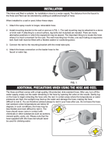
2-7.WATER
CONTROL
KIT
(Optional)
CON
NECTIONS
When
a
water-cooled
gun
is
to
be
used,
connect
a
hose
from
the
water
supply
to
the
Water
input
fitting
at
the
rear
of
the
control.
This
fitting
has
a
left-hand
thread.
The
water
output
hose
routed
through
the
boom
is
to
be
connected
to
the
Water
output
fitting
at
the
front
of
the
control.
A
water
drain
hose
connects
to
the
adapter
at
the
weld
terminal
on
the
drive
assembly
and
is
routed
through
the
boom
to
an
appropriate
disposal.
2-8.
SHIELDING
GAS
CONNECTIONS
A
hose
is
supplied
with
the
unit
for
making
connections
from
the
shielding
gas
source
to
the
Shielding
Gas
input
fitting
at
the
rear
of
the
control.
These
fittings
have
right-hand
threads.
The
gas
hose
routed
through
the
boom
connects
to
the
Shielding
Gas
output
fitting
at
the
front
of
the
control.
.
7
Figure
2-4.
Drive
Roll
Installation
TB-080
030
I
TB-080
158
Figure
2-5.
U-Cog
Drive
Rolls
Installation
2-9.
WELDING
GUN
CONNECTIONS
A.
Outlet
Wire
Guide
(Figure
2-4)
Page
4

~tletguideis
provided
as
part
of
the
gun
~
assembly.
~
1.
Loosen
the
outlet
guide
adjustable
knob
(16).
I
Wire
guides
should
be
installed
so
that
the
tip
of
I
the
guide
is
as
close
to
the
drive
roll
as
possible
without
touching.
2.
Insert
the
adapter
(14)
which
includes
the
installed
outlet
guide
(15)
into
the
drive
assembly
opposite
the
inlet
wire
guide
as
illustrated
in
Figure
24.
3.
Tighten
the
outlet
guide
adjustable
knob
(16).
B.
Weld
Cable
(Figure
2-4)
A
terminal
is
provided
on
the
lower
portion
of
the
drive
assembly
to
serve
as
a
junction
point
for
joining
together
the
weld
cables
from
the
welding
power
source
and
the
gun
(if
so
equipped).
Remove
weld
terminal
nut
(18),
lock
washer,
and
flat
washer;
slide
the
weld
cable
from
the
gun
onto
weld
terminal;
replace
flat
washer,
lock
washer,
nut
(18)
and
tighten.
C.
Shielding
Gas
The
shielding
gas
hose
from
the
gun
is
to
be
connected
to
the
gas
hose
which
protrudes
from
the
motor
end
of
the
boom.
~tegral
gas
inp
ut
nt
ting
is
p
rovided
on
the
weld
head
for
guns
utilizing
this
type
of
con
nection.
See
the
appropriate
welding
gun
Owners
Manual
for
instructions
on
making
this
connection.
If
the
hose
is
provided
with
a
fitting,
cut
the
fitting
of
1,
and
push
the
hose
onto
the
barbed
fitting
on
the
drive
assembly.
D.
Switdh
Control
The
plug
from
the
gun
switch
is
to
be
inserted
fully
into
the
switch
control
cable
and
rhe
locking
ring
rotated.
When
the
switch
connected
across
this
receptacle
is
closed,
the
contactor
in
the
welding
power
source
will
energize,
shielding
gas
will
flow
and
wire
will
begin
to
feed.
E.
Water
(If
Applicable)
Connect
the
water
input
hose
from
the
gun
to
the
water
output
hose
from
the
control.
Connect
the
water
return
hose
from
the
gun
to
the
adapter
at
the
weld
terminal
on
the
drive
assembly.
A
re
ducing
bushing
is
provided
to
accept
a
5/8-18
L.H.
fitting.
If
the
bushing
is
removed,
a
7/8-14
L.H.
fitting
can
be
accomodated.
2-10.
BOOM
ADJUSTMENTS
(Figure
2-6)
A.
Weight
Lift
Adjustment
I
Ensure
that
during
all
adjustment
procedures,
full
threads
on
the
adjustment
rod
are
maintained
through
the
yoke.
If
full
threads
are
not
main
tained,
the
boom
may
suddenly
drop
down
and
cause
injury
to
personnel
or
damage
to
equipment.
amount
of
weight
that
the
boom
can
lift,
loosen
the
jam
nut
and
rotate
the
adjustment
rod
so
that
the
adjustment
rod
threads
into
the
yoke.
When
the
proper
adjustment
is
obtained,
tighten
the
jam
nut
against
the
base
of
the
yoke.
If
a
lighter
gun
is
used
with
the
Swingarc.
rotate
the
adjustment
rod
so
that
the
adjustment
rod
threads
out
of
the
yoke.
Figure
2-6.
Boom
Adjustments
B.
Locking
Knob
TB-003
40g-A
By
rotating
the
Locking
Knob
in
a
clockwise
direction,
the
boom
may
be
held
in
any
desired
position.
Rotating
the
Locking
Knob
in
a
counterclockwise
direction
will
permit
the
boom
to
free
travel.
Changing
the
position
of
the
Locking
Knob
to
the
other
threaded
holes
provided
along
the
side
of
the
swivel
plate,
limits
the
lift
of
the
boom
to
50
degrees
or
40
degrees
respectively
during
free
travel.
2-11.
MOTOR
CONTROL
CONNECTION
(Figure
2-7)
115
Volt
Contactdr
Receptacle
Figure
2-7.
Rear
Panel
Connections
m
TA.049
731
I
Examine
the
motor
control
plug
and
connector
carefully
to
determine
proper
alignment
of
the
pin
arrangement
with
the
contacts.
A
receptacle
is
provided
for
connecting
the
motor
control
plug
to
the
control.
Align
keyways
and
insert
the
plug
from
the
control
end
of
the
boom
into
the
receptacle
and
rotate
the
plug
threaded
collar
clockwise
as
far
as
possible.
2-12.
SWITCH
CONTROL
CONNECTION
(Figure
3-1)
A
receptacle
is
provided
for
making
switch
control
con
nections.
Align
keyways
and
insert
the
plug
from
the
control
end
of
the
boom
into
the
receptacle
and
rotate
the
plug
threaded
collar
clockwise
as
far
as
possible.
Nut
Justment
Rod
Locking
The
amount
of
weight
which
the
boom
can
retract
into
the
upright
position
when
released
can
be
varied
by
ad
justing
the
jam
nut
and
adjustment
rod
located
at
the
base
of
the
boom.
If
a
heavier
gun
is
installed
on
the
end
of
the
boom
thereby
making
it
necessary
to
increase
the
OM-1522
Page
5

2-13.
WELD
CABLE
CONNECTION
2-it
ADJUSTMENT
OF
HUB
TENSION
(Figure
2-2)
A
weld
cable
extends
out
of
the
wire
support
end
of
the
boom
for
making
secondary
connections
to
the
welding
power
source.
The
end
of
the
weld
cable
is
equipped
with
a
terminal
for
a
1/2
stud.
2-14.
115
VOLT
AND
CONTACTOR
CONNECTION
(Fig
ure
2-7)
A
10
ft.
cable
is
provided
for
115
volts
ac
power
and
contactor
control
connections
between
control
and
welding
power
source.
Align
keyways
and
insert
the
plug
into
receptacle
on
the
control
and
rotate
the
threaded
collar
clockwise
as
far
as
possible.
Insert
the
115
volts
power
plug
into
the
115
volts
ac
receptacle
on
the
welding
power
source
and
rotate
clockwise
to
lock
in
place.
Insert
contactor
control
plug
into
the
contactor
control
receptacle
on
the
welding
power
source
and
rotate
clockwise
to
lock
in
place.
~n~olv
I
be
electrically
h~ternally
and
ready
to
operate
as
soon
as
the
115
volts
power
plug
is
connected
to
the
115
volts
ac
source
and
the
welding
power
source
is
energized.
It~TANT
I
The
contactor
control
circuitry
that
is
to
be
used
in
I
conjunction
with
this
control/feeder
must
be
of
the
type
that
operates
on
115
volts
60
Hertz
power.
This
is
necessary
because
the
control
will
supply
115
volts
ac
through
the
contactor
control
cable
whenever
the
gun
switch
is
closed.
2-15.
REMOTE
CONTROL
CONNECTION
(Figure
3-1)
A
receptacle
is
provided
for
connecting
a
remote
control
to
the
unit.
Align
keyways
and
insert
the
plug
from
the
remote
control
into
the
receptacle
and
rotate
the
threaded
collar
clockwise
as
far
as
possible.
2-16.
INSTALLATION
OF
SPOOL-TYPE
WIRE
(Figure
2-2)
1.
Remove
the
retaining
ring
(12).
2.
Slide
the
spool
of
wire
onto
the
hub
(4)
so
that
the
wire
will
feed
off
the
top
of
the
spool.
The
spool
turns
in
a
clockwise
direction.
3.
Rotate
the
spool
until
the
hole
in
the
spool
aligns
with
the
pin
in
the
hub
(4).
Slide
the
spool
onto
the
hub
until
it
seats
against
the
back
flange
of
the
hub.
4.
Depress
the
two
spring-loaded
stops
(11)
on
the
retaining
ring
(12)
and
slide
the
retaining
ring
(12)
into
proper
position
on
the
hub
(4).
Release
the
two
stops
(11).
2-17.
INSTALLATION
OF
REEL-TYPE
WIRE
(Figure
2-3)
1.
Loosen
the
four
wing
nuts
(3)
on
the
fingers
(2)
of
the
wire
reel
(1).
2.
Pull
the
four
fingers
(2)
out
until
they
can
be
rotated
toward
the
center
of
the
reel
(1).
3.
Install
the
wire
onto
the
reel
(1)
over
the four
fingers
(2).
Ensure
that
the
wire
feeds
off
the
top
of
the
reel
(1).
The
reel
(1)
turns
in
a
clockwise
direction.
4.
Rotate
the
four
fingers
(2)
back
to
their
proper
position.
Tighten
the
four
wing
nuts
(3).
Check
the
hub
tension
by
slowly
pulling
the
wire
toward
the
feed
roll.
The
wire
should
unwind
freely,
but
the
hub
tension
should
be
sufficient
to
keep
the wire
taut
and
prevent
backlash
when
the
wire
feeding
ceases.
If
adjustment
is
required,
loosen
or
tighten
the
hex
nut
(10)
on
the
end
of
the
spindle
support
shaft
(1)
accordingly.
2-19.
WELDING
WIRE
THREADING
CAUTION
I
Prior
to
threading
the
welding
wire
~gh
the
gun,
ensure
that
weld
power
is
not
available
at
the
weld
head.
-I
1.
Install
the
wire
(reel-type
or
spool-type)
as
instructed
in
Section
2-16
or
2-17.
2.
Cut
off
any
portion
of
the
free
end
of
the
wire
which
is
not
straight.
Ensure
that
the
cut
end
is
free
from
rough
surfaces
to
permit
proper
feeding.
3.
Route
the
wire
through
the
wire
guide
tube
on
the
side
of
the
boom,
over
the
wire
pulley,
and
to
the
drive
assembly.
4.
Loosen
the
wing
nut
on
the
drive
roll
pressure
adjustment,
pivot
the
pressure
adjustment
free
of
the
cover,
and
pivot
the
pressure gear
assembly
away
until
it is
in
an
open
position.
5.
Feed
the
wire
through
the
inlet
wire
guide,
past
the
drive
rolls,
and
on
into
the
outlet
wire
guide.
Feed
approximately
4
inches
of
wire
into
the
outlet
wire
guide.
m
If
when
the
gear
cover
is
closed
the
U-Cog
drive
rolls
U
are
not
aligned
properly
(see
Section
2-6),
pivot
the
gear
cover
away
from
the
drive
gear
and
rotate
the
pressure
gear
one
tooth.
6.
Pivot
the
gear
cover
closed
making
sure
the
teeth
on
the
pressure
gear
mesh
with
the
teeth
on
the
drive
gear.
The
welding
wire
must
also
be
in
the
grooves
of
the
drive
rolls.
7,
Pivot
the
pressure
adjustment
wing
nut
until
the
washer
on
the
pressure
adjustment
is
seated
on
top
of
the
gear
cover.
8.
Turn
the
pressure
adjustment
wing
nut
in
a
clockwise
direction
until
the
drive
rolls
are
tight
against
the
welding
wire.
Do
not
overtighten.
Further
adjustment
to
attain
desired
clamping
pressure
can
be
made
after
the
welding
power
source
and
the
control/feeder
are
put
into
operation:
9.
Draw
the
gun
cable
out
straight.
10.
Energize
the
welding
power
source
(if
the
115
Volts
AC
receptacle
on
the
welding
power
source
is
uti
lized).
11.
Place
the
control
POWER
switch
in
the
ON
position.
12.
Depress
the
INCH
switch.
This
will
run
the
welding
wire
through
the
gun
without
placing
weld
current
on
the
welding
wire.
Release
the
INCH
switch
when
the
welding
wire
extends
approximately
one
inch
out
of
the
gun
tip.
Page
6

SECTION
3
-
FUNCTION
OF
CONTROLS
3-1.
POWER
SWITCH
(Figure
3-1)
Placing
the
POWER
switch
on
the
control
in
the
ON
position
will
apply
115
volts
ac
to
the
unit
and
thereby
place
it
in
an
operational
condition,
ready
to
feed
wire
and
permit
shielding
gas
to
flow.
Placing
the
POWER
switch
in
the
OFF
position
will
shut
the
control/feeder
down.
~ng
the
P0
WER
switch
in
the
OFF
pos
ition
d
oes
not
remove
power
from
all
of
the
controls
internal
circuitry.
Completely
terminate
all
electrical
power
to
the
control
by
removing
the
115
volts
ac
plug
from
its
power
supply,
and
ensure
that
machinery
lockout
procedures
have
been
employed
on
the
welding
power
sources
input
line
(see
Instruction
Manual
on
welding
power
source)
before
attempting
any
inspec
~ion
or
work
inside
the
unit.
p
3-2.
REMOTE
CONTROL
RECEPTACLE
AND
SWITCH
(Figure
3-1)
The
remote
control
receptacle
is
provided
for
use
in
conjunction
with
Certain
optional
controls.
If
a
remote
control
is
to
be
used,
make
connections
as
instructed
in
Section
2-15
and
place
the
Remote
Control
switch
in
the
REMOTE
position.
When
changing
the
position
of
the
switch
it is
necessary
to
pull
out
on
the
toggle.
If
a
remote
control
is
not
to
be
used,
place
the
Remote
Control
switch
in
the
STANDARD
position.
SECTION
4
-
SEQUENCE
4-1.
GAS
METAL-ARC
WELDING
(GMAW)
1.
Make
all
necessary
connections
as
instructed
in
Section
2.
2.
Place
the
control
unit
Remote
Control
switch
in
the
STANDARD
position.
3.
Energize
the
welding
power
source.
4.
Place
the
POWER
switch
on
the
control
in
the
ON
position,
5.
Rotate
the
WIRE
SPEED
control
until
the
desired
wire
speed
is
displayed
on
the
INCHES
PER
MINUTE
meter.
6.
Turn
on
the
shielding
gas
at
the
source.
7.
Depress
the
PURGE
button
for
one
minute.
3-3.
PURGE
BUTTON
(Figure
3-1)
The
PURGE
button
is
a
momentary
contact
switch.
This
switch
will
energize
the
gas
solenoid
and
purge
the
shielding
gas
line
of
the
gun.
The
PURGE
button
also
allows
the
shielding
gas
regulator
to
be
adjusted
without
energizing
the
welding
circuit.
3-4.
INCH
SWITCH
(Figure
3-1)
The
INCH
switch
is
a
spring
loaded
toggle
switch.
When
actuated
it
completes
the
circuit
to
the
motor
without
having
to
depress
the
gun
trigger
switch.
This
switch
will
permit
inching
of
the
wire
at
whatever
setting
the
WIRE
SPEED
control
is
at,
without
energizing
the
welding
circuit
or
the
shielding
gas
valve,
3-5.
WIRE
SPEED
CONTROL
(Figure
3-1)
A
ten
turn
WIRE
SPEED
control
provides
a
means
of
determining
the
rate
at
which
welding
wire
will
be
fed
into
the
weld.
Rotating
the
WIRE
SPEED
control
in
a
clockwise
direction
will
increase
the
rate
of
the
wire
feed.
3-6.
INCHES
PER
MINUTE
METER
(Figure
3-1)
This
meter
displays
the
wire
speed
in
inches
per
minute.
Before
the
gun
trigger
is
depressed,
the
meter
displays
wire
speed
as
set
by
the
WIRE
SPEED
control.
During
welding
the
meter
displays
actual
wire
speed
as
set
by
the
WIRE
SPEED
control.
3-7.
RESET
CIRCUIT
BREAKER
(Figure
3-1)
A
circuit
breaker
provides protection
to
the
feeder
motor.
In
the
event
the
motor
should
be
placed
in
an
overload
condition,
the
breaker
would
trip
and
suspend
all
output.
Should
this
breaker
trip,
the
RESET
button
would
have
to
be
manually
depressed
in
order
to
reset
the
circuit
breaker,
3-8.
BURNBACK
CONTROL
(OptionaU
The
burnback
circuitry
in
this
control
provides
a
means
of
keeping
the
welding
wire
from
sticking
to
the
workpiece
after
the
gun
switch
is
released.
The
burnback
capability
in
this
control/feeder
will,
depending
upon
the
setting
of
the
BURNBACK
control,
keep
weld
current
present
on
the
welding
wire
from
0
to
15
cycles
after
the
wire
has
stopped
feeding.
This
delay
action
will
permit
the
welding
wire
to
burn
back
to
a
point
where
it
will
neither
stick
to
the
workpiece
nor
the
contact
tube.
If
the
welding
wire
sticks
to
the
contact
tube,
rotate
the
BURNBACK
control
to
a
more
counterclockwise
position.
If
the
welding
wire
sticks
to
the
workpiece,
rotate
the
BURNBACK
control
to
a
more
clockwise
position.
OF
OPERATION
8.
Hold
the
tip
of
the
gun
approximately
1/2
inch
from
the
workpiece.
9.
Depress
the
trigger
on
the
gun
handle.
Gas
will
start
to
flow
and
wire
will
start
to
feed
if
drive
roll
pressure
is
properly
adjusted
to
prevent
slippage.
If
wire
slippage
is
noticed,
tighten
the
drive
roll
pressure
adjustment
wing
nut
1/2
turn
clockwise.
Repeat
until
slippage
stops.
Do
not
overtighten
wing
nut.
~lding
wire
and
all
me
ta
I
pa
rts
in
con
tact
w
ith
it
are
energized
while
welding.
Do
not
touch
the
welding
wire
or
any
metal
part
making
contact
with
it.
4-2.
SHUTTING
DOWN
1.
Turn
off
the
shielding
gas
at
the
source.
2.
Place
the
POWER
switch
on
the
control
in
the
OFF
position.
3.
Turn
off
all
associated
equipment.
Fuse
inches
Per
Minute
Purge
Meter
Button
Inch
Switch
I
~/
Circuit
H
LIIIIIIIJ;?
Breaker~l~'
Power
Switch
II
I
Wire
Speed
Control
Remote
Control
Switch
Switch
Control
Receptacle
Remote
Control
Receptacle
TA-049
732
Figure
3-1.
Control
Components
I
Prior
to
welding,
it
is
imperative
that
proper
protective
I
clothing
(welding
coat
and
gloves)
and
eye
protection
(glasses
and
welding
helmet)
be
put
on.
Failure
to
comply
may
result
in
serious
or
permanent
bodily
damage.
OM-1522
Page
7

I
If
welding
is
performed
in
a
confined
area,
failure
to
turn
off
the
shielding
gas
Supply
could
result
in
a
build-up
of
gas
fumes,
thereby
endangering
personnel
reentering
the
welding
area.
I
I
SECTION
5-MAINTENANCE
5-1.
INSPECTION
AND
UPKEEP
Usage
and
shop
conditions
will
determine
the
frequency
and
type
of
maintenance.
Inspect
equipment
as
follows:
1.
Make
sure
welding
power
source
is
shut
down.
2.
Inspect
gun
for
broken
areas,
cracks
and
loose
parts:
tighten,
repair,
and
replace
as
required.
3.
Carefully
remove
any
weld
spatter
or
foreign
matter
which
may
accumulate
around
the
nozzle
orifice.
Use
a
hardwood
stick,
never
a
metal
tool.
4.
Repair
or
replace,
as
required,
all
hos.e
and
cable;
give
particular
attention
to
frayed
and
cracked
insulation
and
areas
where
it
enters
equipment.
5-2.
CLEANING
OF
DRIVE
ROLLS
Occasionally
it
will
become
necessary
to
clean
the
wire
groove
on
the
drive
rolls.
This
cleaning
operation
can
be
performed
with
a
wire
brush.
To
clean
the
wire
grooves
it
will
be
necessary
to
first
remove
the
drive
roll(s)
(see
Section
2-6
for
removal
and
installation
instructions).
~uretoproperlymai~:fhedriverolIscanresult
in
a
build-up
of
wire
particles
which
will
decrease
the
~
efficiency
of
the
wire
feeding
operation.
5.
Remove
grease
and
grime
from
components;
moisture
from
electrical
parts
and
cable.
6.
Blow
out
the
gun
wire
guide
liner
with
compressed
air
when
changing
wire.
This
will
remove
any
metal
chips
and
dirt
that
may
have
accumulated.
~dous
voltages
are
present
on
~nternalcir
cuitry
of
this
unit
as
long
as
power
is
connected.
Disconnect
power
before
attempting
any
inspection
or
work
on
the
inside
of
the
unit.
Troubleshooting
of
internal
circuitry
should
be
performed
by
qualified
personnel
only.
It
is
assumed
that
proper
installation
has
been
made,
according
to
Section
2 of
this
manual,
and
that
the
unit
has
been
functioning
properly
until
this
trouble
developed.
Use
this
chart
in
conjunction
with
the
circuit
diagram
while
performing
troubleshooting
procedures.
If
the
trouble
is
not
remedied
after
performing
these
procedures,
the
nearest
Factory
Authorized
Service
Station
should
be
contacted.
In
all
cases
of
equipment
malfunction,
the
manufacturers
recommendations
should
be
strictly
followed.
The
following
chart
is
designed
to
diagnose
and
provide
remedies
for
some
of
the
troubles
that
may
develop
in
this
unit.
TROUBLE
PROBABLE
CAUSE
REMEDY
Depressing
gun
switch
will
not
energize
control/feeder.
Electrode
wire
is
not
energized
and
shielding
gas
does
not
flow.
Control
POWER
switch
in
wrong
position
or
defective.
Place
switch
to
ON
position.
Replace
defective
POWER
switch.
115
volts
input
fuse
Fl
open.
Replace
fuse
Fl.
115
volts
contactor
control
plug
is
not
secure
in
receptacle.
Secure
plug
in
receptacle.
Plug
from
gun
switch
is
not
secure
in
switch
control
cable
on
boom,
Insert
plug
fully
into
switch
control
cable
and
rotate
locking
ring.
Plug
from
switch
control
cable
is
not
secure
in
Switch
Control
receptacle.
Secure
plug
in
Switch
Control
receptacle.
Coil
of
relay
CR1
defective.
Replace
relay
CR1.
Circuit
breaker
CB1
tripped.
Manually
reset
circuit
breaker
by
depressing
the
button
on
the
front
panel
of
the
control
labeled
RESET.
Wire
feeds,
shielding
gas
flows,
but
electrode
wire
is
not
energized.
~
115
volts
contactor
control
plug
is
not
secure
in
contactor
receptacle
on
welding
power
source.
Secure
plug
in
receptacle.
Defect
in
welding
power
source.
.
See
TROUBLESHOOTING
Section
in
welding
power
source
instruction
manual.
5-3.
FUSE
(Figure
3-1)
The
control
is
protected
from
damage
due
to
an
internal
short
or
excessive
overload
by
fuse
Fl.
Should
Fl
open,
the
control
would
be
completely
inoperative.
SECTION
6
-
TROUBLESHOOTING
Page
8

Wire
feeds
erratically.
Pressure
on
drive
rolls
is
insufficient,
Rotate
pressure
adjustment
wing
nuts
clockwise
in
1/4
turn
increments
until
wire
slippage
stops.
Drive
roll
is
too
large
for
wire
size
Change
to
proper
size
drive
roll.
See
Section
2-6.
being
used.
Worn
drive
roll.
Replace
drive
roll.
See
Section
2.6.
Dirt
in
drive
roll.
Clean
drive
roll
as
instructed
in
Section
5-2.
if
it
becomes
necessary
to
replace
any
fuse
in
the
control/feeder,
ensure
that
a
fuse
of
the
proper
size
is
used.
OM-1522
Page
9

38
~rok
PURGE
Circuit
Diagram
No.
C-081
944-A
Figure
6-1.
Circuit
Diagram

April
1979
FORM:
OM-1522
PARTS
LIST
Effective
With
Serial
No.
HK270136
MODEL
SWINGARC
DIGITAL
-
1
12
SWINGARC
DIGITAL
-
1
16

Figure
A
Main
Assembly
TD-049
746
/