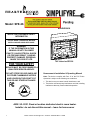
Heatilator Simplifyre 26 Installation guide
- Category
- Fireplaces
- Type
- Installation guide
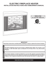
Heatilator Simplifyre 26 is an electric fireplace designed to provide warmth and a cozy ambiance to your home. With its realistic flame effect and adjustable heat settings, you can enjoy the beauty of a fireplace without the hassle of wood or gas.
Features:
- Realistic flame effect
- Adjustable heat settings
- Remote control
- Easy installation
- UL listed for safety
Possible use cases:
- Warm up a room: Use the Heatilator Simplifyre 26 to quickly warm up a chilly room.
- Create a cozy atmosphere: The realistic flame effect and adjustable heat settings can create a cozy and inviting atmosphere in any room.


-
 1
1
-
 2
2
-
 3
3
-
 4
4
-
 5
5
-
 6
6
-
 7
7
-
 8
8
-
 9
9


Heatilator Simplifyre 26 Installation guide
- Category
- Fireplaces
- Type
- Installation guide
Heatilator Simplifyre 26 is an electric fireplace designed to provide warmth and a cozy ambiance to your home. With its realistic flame effect and adjustable heat settings, you can enjoy the beauty of a fireplace without the hassle of wood or gas.
Features:
- Realistic flame effect
- Adjustable heat settings
- Remote control
- Easy installation
- UL listed for safety
Possible use cases:
- Warm up a room: Use the Heatilator Simplifyre 26 to quickly warm up a chilly room.
- Create a cozy atmosphere: The realistic flame effect and adjustable heat settings can create a cozy and inviting atmosphere in any room.
Ask a question and I''ll find the answer in the document
Finding information in a document is now easier with AI
Related papers
Other documents
-
Hearth and Home Technologies SFE-35 User manual
-
-
 MHS Boilers EF500 Installation Instructions Manual
-
LightShow 36629 Installation guide
-
Dimplex C3P18C9-2030W Operating instructions
-
Gemmy AppLights 39109 User manual
-
Savoy House 9-4050-1-SN Operating instructions
-
Ningbo DBL2000-BX Operating instructions
-
Heat & Glo RCE Install Manual
-
