Page is loading ...

1
Dissolved Oxygen
Bench Meter
HI2400
Instruction Manual
www.hannainst.com

2
Dear Customer,
Thank you for choosing a Hanna Instruments product.
Please read this instruction manual carefully before using these
instruments.
This manual will provide you with the necessary information for correct
use of these instruments, as well as a precise idea of their versatility.
If you need additional technical information, do not hesitate to e‑mail
us at [email protected] or view our worldwide contact list at
www.hannainst.com.
All rights are reserved. Reproduction in whole or in part is prohibited
without the written consent of the copyright owner.

3
PRELIMINARY EXAMINATION
..........................................................4
GENERAL DESCRIPTION .................................................................. 4
PROBE FUNCTIONAL DESCRIPTION ..................................................5
FUNCTIONAL DESCRIPTION .............................................................6
SPECIFICATIONS ............................................................................ 7
OPERATIONAL GUIDE .....................................................................8
DO CALIBRATION .........................................................................11
GOOD LABORATORY PRACTICE (GLP) ..............................................13
SETUP ........................................................................................14
LOGGING .....................................................................................19
TEMPERATURE CALIBRATION (for technical personnel only) .............22
PC INTERFACE .............................................................................24
PROBE AND MEMBRANE MAINTENANCE ........................................ 28
TROUBLESHOOTING GUIDE ..........................................................29
ACCESSORIES .............................................................................. 30
TABLE OF CONTENTS

4
GENERAL DESCRIPTION
PRELIMINARY EXAMINATION
HI2400 is a logging microprocessor‑based DO/Temperature bench meter.
It can store up to 100 lots in memory, with up to 8000 readings.
These readings can be transferred to a computer for further analysis or
permanent storage.
Dissolved Oxygen is indicated in ppm (parts per million) or in %.
All measurements are automatically compensated for temperature.
Salinity compensation in water allows direct determination of Dissolved
Oxygen in saline waters and altitude compensation readjusts for the
altitude variance.
The Dissolved Oxygen probe has a membrane covering the polarographic
sensors and a built‑in thermistor for temperature measurements and
compensation.
This permeable PTFE membrane isolates the sensor elements from the
testing solution, but allows Oxygen to pass through. When a voltage is
applied across the sensor, oxygen that has passed through the membrane
reacts causing a current flow, and hence determining a reading.
Remove the instrument from the packing material and examine it carefully
to make sure that no damage has occured during shipping. If there is any
damage, please contact your local Hanna Instruments Office.
Each instrument is supplied with:
• HI76407/2 DO probe with 2 m (6.7’) cable
• HI76407A membrane cap (2 pcs)
• HI7041S electrolyte solution (30 ml)
• 12 VDC power adapter
• Instruction Manual
Note: Save all packing material until you are sure that the instrument
functions correctly. All defective items must be returned in their
original packing with the supplied accessories.

5
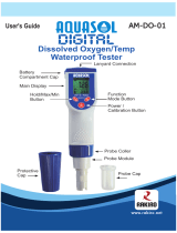
1. DO Probe
2. Protective Cap
3. Watertight Shielded Cable
4. Polypropylene Probe Body
5. Temperature Sensor
6. O‑Ring Seal
7. Silver Chloride Anode
8. Platinum Cathode (sensor)
9. Oxygen Permeable PTFE Membrane
10. Membrane Cap
7
8
10
9
3
4
1
2
4
5
6
PROBE FUNCTIONAL DESCRIPTION

6
1) Liquid Crystal Display (LCD).
2) CAL key, to enter and exit calibration mode.
3) CFM/GLP key, to confirm calibration selection, different setup values
or to display Good Laboratory Practice information.
4) ºC key, to manually increase temperature value or other param‑
eters.
5) ºC key, to manually decrease temperature value or other param‑
eters.
6) SETUP key, to enter/exit SETUP mode.
7) RANGE key, to select measurement range (% or ppm), switch
to focused data in SETUP or toggle between standard value and
temperature during calibration.
8) LOG/CLR key, to store a value into memory, or to select to delete
log records.
9) RCL key, to enter and exit view memory mode.
10) ON/OFF switch.
11) Power supply socket.
12) USB connector.
13) DO probe connector.
FUNCTIONAL DESCRIPTION
Front Panel
Rear Panel

7
SPECIFICATIONS
RANGE
0.00 to 45.00 ppm
0.0 to 300.0%
0.0 to 50.0 ºC (32.0 to 122°F)
RESOLUTION
0.01 ppm
0.1%
0.1 °C
ACCURACY
(@20 °C / 68 °F)
±1.5% of full scale or ±1 digit,
whichever is greater
±0.2 ºC (excluding probe error)
Typical EMC Deviation
±1.5% of full scale
±0.5 ºC
DO Calibration
Single or double point at 0%
(HI7040) and 100% (in air)
Altitude
Compensation
Resolution
0 to 4,000 m (13,120’)
100 m (328’)
Salinity
Compensation
Resolution
0 to 40 g/l
1 g/l
Temperature
Compensation
0.0 to 50.0 ºC
(32.0 to 122 ºF)
Probe HI76407/2 with 2 m (6.6’) cable
Logging interval
5, 10, 30 seconds
or 1, 2, 5, 10, 15, 30, 60, 120,
180 minutes
PC communication Optoisolated USB
Power supply 12 VDC adapter
Dimensions 235 x 222 x 109 mm (9.2 x 8.7 x 4.3”)
Weight
1.3 Kg (2.9 lb)
kit with holder 2.1 Kg (4.6 lb)
Environment
0 – 50 ºC (32 ‑ 122 ºF)
max. 95% RH non condensing
Warranty 2 years

8
Shipping
cap
black
red
FILL FIRST
THEN TAP
THEN SCREW
BACK ON
OPERATIONAL GUIDE
POWER CONNECTION
Plug the 12 VDC adapter into the power supply socket.
Notes: • This instrument use non volatile memory to retain the cali-
bration parameters and all the other settings even when unplugged.
• Make sure a fuse protects the main line.
PROBE CONNECTION AND PREPARATION
To take measurements, connect the DO
probe to the meter securely by aligning
the pins with the socket located on the
back of the meter, pushing the plug in and
tightening the threaded ring.
Probes shipped from Hanna Instruments
are dry. To hydrate the probe and prepare
it for use, connect it to the meter and
proceed as follows:
1. Remove the red and black plastic cap.
This cap is for shipping purposes and
can be thrown away.
2. Wet the sensor by soaking the bottom
2½ cm (1”) of the probe in electrolyte
(HI7041S) for 5 minutes.
3. Rinse the membrane cap (HI76407A
supplied in the kit with the meter)
with electrolyte solution while shaking
it gently. Refill with clean electrolyte
solution.
4. Tap gently the sides of the membrane
cap with your finger tip to ensure that
no air bubbles are trapped. To avoid
damaging the membrane, do not tap
it directly on the bottom.
5. Make sure that the rubber O‑ring sits
properly inside the membrane cap.
6. With the sensor facing down, slowly screw the cap clockwise. Some
electrolyte will overflow.
When not in use and during polarization (see page 9), use the protective
transparent cap supplied in the kit with the meter.

9
INSTRUMENT START-UP
• Turn the instrument on by pressing the ON/OFF switch.
• All LCD tags are displayed and a beep is generated while the instru‑
ment performs a self test.
• The instrument will display “ ” blinking until initialization is
complete.
• After a few seconds “Cond” message appears on the LCD to inform the
user that the probe is in auto‑conditioning (automatic polarization)
mode.
• When this message disappears, the probe is polarized and the
instrument can be calibrated.
• If the probe is disconnected, the meter will display “----”.
PROBE POLARIZATION
The probe is under polarization with a fixed voltage of approximately
800 mV. Probe polarization is essential for stable measurements with
the same recurring degree of accuracy.
With the probe properly polarized, oxygen is continually consumed when
it passes through the sensitive diaphragm and dissolves in the electrolyte
solution contained in the probe. If polarization is interrupted, the elec‑
trolyte solution continues to be enriched with oxygen until it reaches an
equilibrium with the surrounding solution.
Whenever measurements are taken with a non‑polarized probe, the
oxygen level revealed is both that of the tested solution, as well as that
present in the electrolyte solution. This reading is incorrect.
The calibration of this instrument is very simple. Before proceeding with
the calibration, make sure the probe is ready for measurements (see
page 8), i.e. the membrane cap is filled with electrolyte and the probe
is connected to the meter and properly polarized.
For an accurate calibration, it is recommended to wait at least 15 minutes
to ensure precise conditioning of the probe. Keep the protective cap on
during polarization time and remove it for calibration and measurements.
Follow the calibration procedure (see page 11).

10
SALINITY AND ALTITUDE COMPENSATION
If the sample contains significant concentration of salinity or if you are
performing measurements at an altitude different from sea level, the
read out values must be corrected, taking into account the lower degree
of oxygen solubility in these situations (see pages 15‑16).
Remember to set the altitude and/or the salinity before taking any DO
measurements. The meter will automatically compensate for these factors.
DO MEASUREMENTS
Make sure that the instrument has been calibrated and the
protective cap has been removed.
• Submerse the tip of the probe in the sample to be
tested. Allow approximately one minute for the reading
to stabilize.
• The Dissolved Oxygen value (in %) is displayed on the primary LCD
and the temperature on the secondary LCD.
• Press RANGE to change the reading from % to ppm and vice‑versa.
For accurate Dissolved Oxygen measurements, a water movement of
0.3 m/s is required. This is to ensure that the oxygen‑depleted membrane
surface is constantly replenished. A moving stream will provide adequate
circulation.
The use of a magnetic stirrer to ensure a certain fluid velocity is rec‑
ommended.
TEMPERATURE MEASUREMENTS
The probe has a built‑in temperature sensor.
The measured temperature is indicated on the secondary LCD as shown
above.
Allow the probe to reach thermal equilibrium before taking any measure‑
ment. This can take several minutes. The greater the difference between
the temperature at which the probe was stored and the temperature of
the sample, the longer the time will be.
Note: If “----” is displayed, the DO probe is not properly connected.
This also indicates the possibility of a broken probe cable. If the
temperature is displayed blinking, the temperature is out of range.

11
DO CALIBRATION
Calibrate the instrument frequently, especially if high accuracy is required.
The instrument can be calibrated in maximum 2 points: 0.0% (zero
calibration) and 100.0% (slope calibration).
The zero calibration of the HI2400 is very stable, therefore this procedure
needs to be performed only whenever the probe or the membrane is
replaced.
However, because the slope calibration is more critical, it is recommended
to perform this procedure every week.
INITIAL PREPARATION
• Pour small quantities of HI7040 Zero Oxygen
solution into a beaker. If possible, use a plastic
beaker to minimize any EMC interferences.
• Make sure the probe is ready for measurements
(see probe preparation on page 8), i.e. the
membrane is filled with electrolyte and the probe
is connected to the meter.
• Switch the meter on by pressing the ON/OFF
switch.
• For an accurate calibration, it is recommended
to wait for at least 15 minutes to ensure precise
conditioning of the probe.
• Remove the protective cap from the DO probe.
• Set the appropriate altitude factor (see page 15). Make sure the
salinity factor is set to zero (see page 16).
H 7040I
HI7040
ZERO CALIBRATION
• Submerse the probe into HI7040 zero oxygen
solution and stir gently for 2‑3 minutes.
• Press CAL. The “~” and “ ” tags will blink on
the LCD until the reading is stable.
• When the reading is stable, “CFM” starts
blinking. Press CFM to confirm the “0.0%” DO
calibration.
• If the reading is within the limits (±15% f.s.),
the meter stores the value (and adjusts the slope
point).

12
OR
• Press CAL. The instrument will return to measure‑
ment mode and will memorize the zero calibration
data. For a two‑point calibration do not press CAL
and follow the procedure below.
SLOPE CALIBRATION
It is suggested to perform the slope calibration in air.
• Rinse the probe in clean water to remove any
residual zero oxygen solution.
Note: If you did not perform the zero calibration procedure, press CAL
and then the ARROW keys to select the 100% DO calibration point.
• Dry the probe tip and allow a few seconds for the LCD reading to
stabilize. The “~” and “ ” tags will blink until the reading is stable.
• When the reading is stable, “CFM” tag starts blinking. Press CFM
to confirm the “100.0%” DO calibration.
• If the reading is within the limits (±15% f.s.), the
meter stores the value (and adjusts the slope point).
• The instrument stores the slope calibration data and
returns to measurement mode.
Notes: • If the reading is not close to the selected value, “WRONG“
tag will blink.
• If the temperature goes out of range during calibration the
“WRONG”, temperature unit tag and both measurements
will blink.
• HI 2400 has automatic buffer recognition function. If the
ARROW keys are pressed to select the desired calibration
value, the automatic buffer recognition function is disabled.

13
GOOD LABORATORY PRACTICE (GLP)
GLP is a set of functions that allows storage and retrieval of data regarding
the maintenance and status of the system.
All data regarding DO calibration is stored for the user to review when
necessary.
LAST DO CALIBRATION DATA
The last DO calibration data is stored automatically after a successful
calibration. To view the DO calibration data, press GLP when the
instrument is in measurement mode.
The instrument will display the time (hh:mm) of the last calibration.
Press the ARROW keys to view the next calibration parameter.
Pressing the key:
• The date of the calibration.
• The calibration standards.
• Press SETUP to view the temperature of the calibration.
• The altitude value.
• The salinity value.
• The instrument ID.

14
SETUP
Setup mode allows viewing and modifying the following parameters:
• Salinity Factor
• Altitude Factor
• Log Interval
• Current Time (hour & minute)
• Current Date (month, day & year)
• Beep Status
• Instrument ID
• Temperature Unit
To enter the Setup mode press SETUP while the instrument is in mea‑
surement mode. Press SETUP again to exit SETUP mode.
Select a parameter with the ARROW keys.
Press CAL if you want to change a parameter value. The selected
parameter will blink.
Press RANGE to toggle between displayed paramet+ers.
Press the ARROW keys to increase or decrease the displayed value.
Press CFM to save the modified value or CAL to escape.
Press the ARROW keys to select the next/previous parameter.
SALINITY FACTOR
Press CAL when the salinity factor is displayed. The salinity factor (“0”
to “40” g/l) and the “CFM” tag will start blinking.
Press ARROW keys to change the salinity factor value.
Press CFM to save the modified value or press CAL to escape without
saving.
The salinity affects the DO concentration, decreasing its value. The next
table shows the maximum oxygen solubility at various temperatures
and salinity levels.

15
ºC
Salinity (g/l) at Sea Level
ºF
0 g/l 10 g/l 20 g/l 30 g/l 35 g/l
0 14.60 13.64 12.74 11.90 11.50 32.0
2 13.81 12.91 12.07 11.29 10.91 35.6
4 13.09 12.25 11.47 10.73 10.38 39.2
6 12.44 11.65 10.91 10.22 9.89 42.8
8 11.83 11.09 10.40 9.75 9.44 46.4
10 11.28 10.58 9.93 9.32 9.03 50.0
12 10.77 10.11 9.50 8.92 8.65 53.6
14 10.29 9.68 9.10 8.55 8.30 57.2
16 9.86 9.28 8.73 8.21 7.97 60.8
18 9.45 8.90 8.39 7.90 7.66 64.4
20 9.08 8.56 8.07 7.60 7.38 68.0
22 8.73 8.23 7.77 7.33 7.12 71.6
24 8.40 7.93 7.49 7.07 6.87 75.2
25 8.24 7.79 7.36 6.95 6.75 77.0
26 8.09 7.65 7.23 6.83 6.64 78.8
28 7.81 7.38 6.98 6.61 6.42 82.4
30 7.54 7.14 6.75 6.39 6.22 86.0
32 7.29 6.90 6.54 6.19 6.03 89.6
34 7.05 6.68 6.33 6.01 5.85 93.2
36 6.82 6.47 6.14 5.83 5.68 96.8
38 6.61 6.28 5.96 5.66 5.51 100.4
40 6.41 6.09 5.79 5.50 5.36 104.0
42 6.22 5.93 5.63 5.35 5.22 107.6
44 6.04 5.77 5.48 5.21 5.09 111.2
46 5.87 5.61 5.33 5.07 4.97 114.8
48 5.70 5.47 5.20 4.95 4.85 118.4
50 5.54 5.33 5.07 4.83 4.75 122.0
Note: The relationship between salinity and chlorinity for sea water
is given by the equation below:
Salinity (g/l) = 1.80655 Chlorinity (g/l)
ALTITUDE FACTOR
Press CAL when the altitude factor is displayed. The altitude factor (“0”
to “4000” m, in steps of 100 m; 1 meter = 3.28 feet) and the “CFM”
tag will start blinking.
Press the ARROW keys to change the altitude factor value.
Press CFM to save the modified value or press CAL to escape without
saving.

16
ºC
Altitude, Meters above Sea Level
ºF
0
m
300
m
600
m
900
m
1200
m
1500
m
1800
m
2100
m
2400
m
2700
m
3000
m
3300
m
3600
m
3900
m
4000
m
0 14.6 14.1 13.613.1 12.6 12.1 11.7 11.2 10.8 10.4 10.0 9.7 9.3 9.0 8.9 32.0
2 13.8 13.3 12.812.4 11.9 11.5 11.0 10.6 10.2 9.9 9.5 9.2 8.8 8.5 8.4 35.6
4 13.1 12.6 12.211.7 11.3 10.9 10.5 10.1 9.7 9.3 9.0 8.7 8.4 8.0 7.9 39.2
6 12.4 12.0 11.511.1 10.7 10.3 9.9 9.6 9.2 8.9 8.6 8.2 7.9 7.6 7.5 42.8
8 11.8 11.4 11.010.6 10.2 9.8 9.5 9.1 8.8 8.4 8.1 7.8 7.5 7.3 7.2 46.4
10 11.3 10.9 10.5 10.1 9.7 9.4 9.0 8.7 8.4 8.1 7.8 7.5 7.2 6.9 6.8
50.0
12 10.8 10.4 10.0 9.6 9.3 8.9 8.6 8.3 8.0 7.7 7.4 7.1 6.9 6.6 6.5 53.6
14 10.3 9.9 9.6 9.2 8.9 8.5 8.2 7.9 7.6 7.4 7.1 6.8 6.6 6.3 6.2 57.2
16 9.9 9.5 9.2 8.8 8.5 8.2 7.9 7.6 7.3 7.0 6.8 6.5 6.3 6.1 6.0 60.8
18 9.5 9.1 8.8 8.5 8.1 7.8 7.6 7.3 7.0 6.8 6.5 6.3 6.0 5.8 5.7 64.4
20 9.1 8.8 8.4 8.1 7.8 7.5 7.3 7.0 6.7 6.5 6.2 6.0 5.8 5.6 5.5 68.0
22 8.7 8.4 8.1 7.8 7.5 7.2 7.0 6.7 6.5 6.2 6.0 5.8 5.6 5.4 5.3 71.6
24 8.4 8.1 7.8 7.5 7.2 7.0 6.7 6.5 6.2 6.0 5.8 5.6 5.4 5.2 5.1 75.2
25 8.3 8.0 7.7 7.4 7.1 6.8 6.6 6.4 6.1 5.9 5.7 5.5 5.3
5.1 5.0 77.0
26 8.1 7.8 7.5 7.2 7.0 6.7 6.5 6.2 6.0 5.8 5.6 5.4 5.2 5.0 4.9 78.8
28 7.8 7.5 7.3 7.0 6.7 6.5 6.2 6.0 5.8 5.6 5.4 5.2 5.0 4.8 4.7 82.4
30 7.6 7.3 7.0 6.8 6.5 6.3 6.0 5.8 5.6 5.4 5.2 5.0 4.8 4.6 4.6 86.0
32 7.3 7.0 6.8 6.5 6.3 6.1 5.8 5.6 5.4 5.2 5.0 4.8 4.7 4.5 4.4 89.6
34 7.1 6.8 6.6 6.3 6.1 5.9 5.6 5.4 5.2 5.0 4.9 4.7 4.5 4.3 4.3 93.2
36 6.8 6.6 6.3 6.1 5.9 5.7 5.5 5.3 5.1 4.9 4.7 4.5 4.4 4.2 4.1 96.8
38 6.6 6.4 6.1 5.9 5.7 5.5 5.3 5.1 4.9 4.7 4.5 4.4 4.2 4.1 4.0 100.4
40 6.4 6.2 5.9 5.7 5.5 5.3 5.1 4.9 4.7 4.6 4.4
4.2 4.1 3.9 3.9 104.4
42 6.2 6.0 5.8 5.6 5.3 5.2 5.0 4.8 4.6 4.4 4.3 4.1 4.0 3.8 3.8 107.6
44 6.0 5.8 5.6 5.4 5.2 5.0 4.8 4.6 4.5 4.3 4.1 4.0 3.8 3.7 3.7 111.2
46 5.8 5.6 5.4 5.2 5.0 4.8 4.7 4.5 4.3 4.2 4.0 3.9 3.7 3.6 3.5 114.8
48 5.7 5.5 5.3 5.1 4.9 4.7 4.5 4.4 4.2 4.0 3.9 3.7 3.6 3.5 3.4 118.4
50 5.5 5.3 5.1 4.9 4.7 4.6 4.4 4.2 4.1 3.9 3.8 3.6 3.5 3.4 3.3 122.0
LOG INTERVAL
Press CAL when log interval is displayed. The log interval and “CFM”
tag is displayed blinking.
Press the ARROW keys to change the custom buffer value.
Press CFM to confirm the selection.
Press CAL to escape without saving.

17
CURRENT TIME
Press CAL when the current time is displayed. The hour and “CFM” tag
will start blinking.
Press the ARROW keys to change the hour.
Press RANGE. The minutes will start blinking.
Press the ARROW keys to change the minutes.
Press CFM to save the modified value.
Press CAL to escape without saving.
CURRENT DATE
Press CAL when the current date is displayed. The month and “CFM”
tag will start blinking.
Press the ARROW keys to change the month.
Press RANGE. The day and “CFM” tag will start blinking.
Press the ARROW keys to change the day.
Press RANGE. The year and “CFM” tag will start blinking.
Press the ARROW keys to change the year.
Press CFM to save the modified value.
Press CAL to escape without saving.

18
TEMPERATURE UNIT
Press CAL when “Unit“ is displayed. The temperature unit and “CFM”
tag will start blinking.
Press the ARROW keys to change the option.
Press CFM to save the modified temperature unit.
Press CAL to escape without saving.
BEEP STATUS
Press CAL when the beep status is displayed. The beep status (“ON” or
“OFF”) and “CFM” tag will start blinking.
Press the ARROW keys to change the beep status.
Press CFM to save the modified value or press CAL to escape without
saving.
INSTRUMENT ID
Press CAL when “InId” is displayed. The instrument ID (“0000“ to
“9999“) and “CFM” tag will start blinking.
Press the ARROW keys to change the instrument ID value.
Press CFM to save the modified instrument ID value.
Press CAL to escape without saving.
Note: The instrument ID is downloaded to a PC as part of a logged
data, set to identify its origin.

19
LOGGING
This function allows the user to log DO (in ppm or %) together with
temperature automatically, for long periods of time. All logged data can
be stored into a PC through the USB port.
The memory used for storing the logged data is divided in 32 pages.
The capacity of each page is 250 samples. The lot number goes from
1 to 100. The maximum capacity of the log memory is 8000 samples.
Each time a new lot starts, it automatically starts from a new page. When
the samples collected for a single lot reach the limit (8000 samples) or
all memory pages are occupied, the meter stops logging automatically.
The appropriate logging interval can be set between 5, 10, 30 seconds or
1, 2, 5, 10, 15, 30, 60, 120, 180 minutes (see SETUP section for details).
LOGGING THE CURRENT DATA
To start the Auto LOG mode press LOG while in
measurement mode.
When the selected interval is reached the instrument will display the
current lot number on the primary LCD line, the record number on the
secondary LCD line and the LOG tag ( see example below: Lot 15 record 22)
followed by the number of free records on the corresponding memory
space.
If there are less than 6 memory locations remaining, the record number
and “Lo” message will be displayed to alert the user.
To stop the Auto LOG mode press LOG again. The “LOG” tag will be
cleared.

20
If the log space is full, the “FULL LOG” message will be displayed and
no more data will be saved.
Note: When pressing any key that is not active, while lot logging
is running, the following message is displayed for a few seconds.
VIEW LOGGED DATA
Press the RCL key while in measurement mode to retrieve the stored
information.
If no lots are memorized, the next messages will be displayed:
Otherwise, the instrument will display “L” and the lot number on the
primary LCD and the number of records on the secondary LCD, “RCL”
tag and “CFM” blinking.
Press the ARROW keys to select a different lot.
Press CFM to view record information. Then the record information will
appear. To view the record number at any time just press the SETUP key.
Use the ARROW keys to scroll through the records.
To view additional information press RANGE:
• The time on the primary LCD, along with “TIME” tag and the seconds
on the secondary LCD.
/