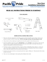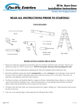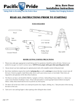
Top mount hangers (2) T-guide (1) Spacers (6) Track stops (2)
Top mount hanger screws (8) T-guide screws (2)
Included Hardware
Washers (6) Anti-jump blocks (2)
Hex lag bolts (6) Anti-jump block screws (4)
Felt Pad (1)
finished floor
WALL
DOOR
FINISHED FLOOR
Plumb the door before fastening
the door guide to the floor.
In the closed
position, the door
should overlap the
wall a minimum of ⅜ʺ
at the top and a
minimum of ½ʺ on
both sides.
The edge of the door
should align with the
end of the track.
Door Prep and Hanger Installaon
Basic Installaon Layouts
GOLDBERG BROTHERS, INC.
Premium Series Top Mount - Installation Instructions
¼ʺ
⅜ʺ
⅞ʺ
Premium hardware set
installed with no casing,
base, or other trim.
Finished Opening
Header / Block
WALL
DOOR
Premium hardware set installed on
track trim board that is equal to or
thicker than casing, base, or other trim.
Finished Opening
Header / Block
WALL
Head Track Block
Side Casing
Base Board
DOOR
Premium hardware set + ½ʺ
extension kit installed where casing,
base, or other trim is up to ½ʺ thick.
Finished Opening
Header / Block
WALL
½ʺ Extensions
DOOR
Side Casing
Base Board
Finished Opening
Extensions
Header / Block
WALL
DOOR
Side Casing
Base Board
⅞ʺor 1¼ʺ
DOOR
TRACK
FINISHED OPENING
DOOR EDGE
½ʺ
3ʺ
⅜ʺ
¾ʺ
5⅛ʺ
1⅜ʺ
⅜ʺ
Place the top mount hangers ¾ʺ from both sides
of the top half of the door. The centerline should
be 3ʺ.
3ʺ
¾ʺ
Using the top mount
screws, attach the
top mount hangers
to the door as shown
in the diagram.
Premium hardware set + ⅞ʺ or 1¼ʺ
extension kit installed where casing, base,
or other trim is greater than ⅝ʺ thick.
2ʺ
Using the T-guide screws, attach the T-guide to the
floor by aligning the edge of the guide with the edge
of the finished opening as shown above.
T-guide Installaon
Stay:
At each end of the track,
place one felt pad strip on
top of the track, 1ʺ in from
the track stop as shown.
1⅛ʺ
Bumper:
For each hanger, place one felt pad
strip on the track stop or the edge
of the hanger as shown.
Goldberg Brothers barn door track and hardware sets come with a one-year manufacturer’s
warranty for defective parts under normal installation and use. Warranty is subject to repair
or replacement of defective components at manufacturer’s discretion and does not include
installation costs.
Goldberg Brothers does not warrant the loss of finish at points where roller is in contact
with track. Goldberg Barn Track is sold as a rustic finished hardware and Goldberg does not
warrant the imperfections seen through the finish in the steel parts. It is part of the look.
With the exception of our stainless steel products, Goldberg Brothers does not warrant any
products installed and used outdoors or where they are exposed to weather, running water
or water condensation. Under these conditions, rust and other damage will naturally occur.
This warranty does not include loss or defects caused by elements outside the control of
Goldberg Brothers, Inc., such as natural disasters, weather, fire, water leakage, abuse,
improper installation, or anything else deemed out of the control of Goldberg Brothers, Inc.
Note: Due to
varying door
thicknesses, make
sure the back
of the hanger
aligns with the
back of the door.
Back of Hanger
Back of door


