Page is loading ...

LR-5200-072 Advanced iDSP Receiver (72 MHz)
LR-5200-216 Advanced iDSP Receiver (216 MHz)
User Manual
© 2018 Listen Technologies Corporation
®
All Rights Reserved
For further details regarding use, adjustment, or programming of your Listen Technologies products visit
our website at www.listentech.com/support-manuals or contact us at +1.801.233.8992 or 1.800.330.0891.

PAGE 2
l
LR-5200 RECEIVER MANUAL
Dear Valued Customer,
Thank you for choosing Listen! We are dedicated to providing you with the highest
quality products available, and take pride in delivering outstanding performance to
ensure you are completely satised.
We independently certify each of our products to the highest quality standards and back
them with a limited lifetime guarantee. We are available to answer any questions you
might have during installation or in the operation of our products. At Listen, it’s all about
you, should you have any comments or suggestions we’re here to listen.
Here’s how to reach us:
+1.801.233.8992
+1.800.330.0891 North America
+1.801.233.8995 fax
www.listentech.com
Thank you and enjoy your listening experience!
Best regards,
Russell Gentner and the Listen Team
• In the few instances where repairs were needed, 99% of all clients indicated that
they were happy with repair turn-around-times and 85% of the time, clients were
without their product for less than 10 days!
• Overall client satisfaction of working with Listen was rated 4.8 out of 5.
• “Please continue with your excellent attitude toward customer satisfaction.
You guys are great!”
• “I’ve never had such good service from any company. Keep up the good work!”
• “You stand behind your product wonderfully.”

LR-5200 RECEIVER MANUAL
l
PAGE 3
TABLE OF CONTENTS
iDSP™ Receivers ………………………………………………………………………………………………………………………………………4
LR-5200 Quick Reference …………………………………………………………………………………………………………………………5
LR-5200 Specications ……………………………………………………………………………………………………………………………6
Safety Cautions ………………………………………………………………………………………………………………………………………7
Hearing Safety …………………………………………………………………………………………………………………………………7
Medical Device Safety ………………………………………………………………………………………………………………………7
Recycling …………………………………………………………………………………………………………………………………………………7
Quick Setup and Operation Instructions …………………………………………………………………………………………………8
1. Unpack Unit ………………………………………………………………………………………………………………………………8
2. Activate Battery …………………………………………………………………………………………………………………………8
3. Charge Battery ……………………………………………………………………………………………………………………………8
4. Connect Ear Phone ……………………………………………………………………………………………………………………9
Using The Neck Loop Lanyard ……………………………………………………………………………………………………9
Using The 3.5mm Headset Extension Cable ………………………………………………………………………………9
5. Turn the Unit On …………………………………………………………………………………………………………………… 10
6. Programmable Channel Select (Listen Button) ……………………………………………………………………… 10
7. Channel Select Mode ……………………………………………………………………………………………………………… 11
Automatic Channel Selection ……………………………………………………………………………………………………………… 12
Manual Channel Selection …………………………………………………………………………………………………………………… 12
Channel Select Mode …………………………………………………………………………………………………………………………… 13
Seek Mode …………………………………………………………………………………………………………………………………………… 13
Disabled ……………………………………………………………………………………………………………………………………………… 14
Listen Button Block ……………………………………………………………………………………………………………………………… 14
Adjust Volume ……………………………………………………………………………………………………………………………………… 15
Battery & Belt Clip ………………………………………………………………………………………………………………………………… 16
Low Battery Indication …………………………………………………………………………………………………………………… 16
Belt Clip Installation/Removal ……………………………………………………………………………………………………… 16
Accessing Battery Compartment …………………………………………………………………………………………………… 17
Reset to Factory Default Settings ………………………………………………………………………………………………………… 17
Advanced Program Features and Listen’s UI Conguration Software …………………………………………………… 18
Super Quiet Mode ………………………………………………………………………………………………………………………… 18
Squelch ………………………………………………………………………………………………………………………………………… 19
Basic Channels and Expanded Channels Modes …………………………………………………………………………… 19
Channel Labels ……………………………………………………………………………………………………………………………… 19
Auto Power Mode ………………………………………………………………………………………………………………………… 19
Unit ID …………………………………………………………………………………………………………………………………………… 20
Brightness Control ………………………………………………………………………………………………………………………… 20
Jack Sense ……………………………………………………………………………………………………………………………………… 20
Unit Information …………………………………………………………………………………………………………………………… 20
Reset to Factory Defaults ……………………………………………………………………………………………………………… 20
Firmware Update …………………………………………………………………………………………………………………………… 20
RF Reception Maximization Strategies ………………………………………………………………………………………………… 21
72 MHz Compatibility Chart ………………………………………………………………………………………………………………… 22
216 MHz Compatibility Chart………………………………………………………………………………………………………………… 23
Troubleshooting LR-5200 Receivers ……………………………………………………………………………………………………… 24
Compliance Notice and FCC Statement ………………………………………………………………………………………………… 25
Warranty ……………………………………………………………………………………………………………………………………………… 26
Contacting Listen ………………………………………………………………………………………………………………………………… 28

PAGE 4
l
LR-5200 RECEIVER MANUAL
iDSP
™
Receivers
The LR-5200 is a powerful Assistive Listening Receiver designed to be compact and simple to use. The
unique design of the iDSP™ receiver family allows them to be worn as a necklace, using the belt clip or con-
cealed in a pocket, making this the most inconspicuous ALS receiver on the market.
Each receiver can be purchased with a Ear Phone/Neck Loop Lanyard that is designed to hold the
receiver like a necklace similar to the Blue Tooth™ transceivers used with many of the today’s hearing
aids. The Ear Phone/Neck Loop Lanyard can be used as the induction loop for those users who have T-coil
enabled hearing aids or cochlear implants, inducing the received audio directly into these T-coil enabled
devices. The Ear Phone/Neck Loop Lanyard also provides the connection to Listen’s Universal Ear Speaker,
Earphones and Headphones, incorporating a short connection cable that plugs directly into the Ear Phone/
Neck Loop Lanyards 3.5mm headset jack located 2/3 of the way up the lanyard. A second 3.5mm extension
cable provided with Listen’s universal earphones provides the length of cable required to place the receiver
in a pocket or using the belt clip.
Earbuds
Ear Speaker
Headset
Belt Clip
Hearing Aid
T-Coil
Ear Phone /
Neck Loop
Lanyard
Extension
Cable

LR-5200 RECEIVER MANUAL
l
PAGE 5
LR-5200 Quick Reference
5. 3.5 mm Output Jacks: Connect Listen Ear Phone/Neck Loop Lanyard for use with T coil hearing aids
or with Universal Ear Speaker or Headphone.
6. Belt Clip: To remove, remove screw and pull belt clip from unit. To install place belt clip in place and
insert screw.
7. Charging Contact: For use with Listen charging tray options.
8. Power On/O: Press and hold for 1 second to turn on. Press and hold for 3 seconds to turn o.
9. LED: Indicates low battery condition and charging status
10. Battery Protective Pull Tab: Remove clear plastic pull tab to activate internal battery connections.
11. Battery Door: Can be removed to access battery and product labeling information.
1. OLED Display Area: Displays battery status, unit ID, channel status, volume status and charge
activation
2. Micro USB: USB charging, programming, rmware updates and inventory dispensing
3. Up/Down Volume Control: Press momentarily to adjust the volume up/down or press and hold to
ramp the volume.
Note: Press and hold both up and down buttons for 5 seconds to activate channel select, use up and
down to change the channel. Momentarily press the power button to save and exit
4. Programmable Channel Select: Cycle through active channels, seek to or lock to a channel.
5. 3.5 mm Output Jacks
6. Belt Clip
7. Charging Contact
8. Power On/O
9. LED
10. Battery
Protective Pull Tab
11. Battery Door
1. OLED Display Area
2. Micro USB
3. Up/Down
Volume Control
4. Programmable
Channel Select

PAGE 6
l
LR-5200 RECEIVER MANUAL
LR-5200 Specications
Audio System Frequency Response 50 Hz - 15 kHz (±3 dB)
System Signal to Noise Ratio SQ enabled 80 dB, SQ disabled 60 dB
SQ enabled 70 dB, SQ disabled 50 dB
System Distortion <2% total harmonic distortion (THD) at 80% deviation
Output/s Two (2) 3.5 mm (0.14 in.) connectors, unbalanced, 0 dBu
nominal output level, 16 mW maximum, impedance 32 ohm
Controls User Controls Power, up/down volume, Listen button for end user
channel selection
Set-up Controls Press and hold up/down volume buttons for 5 seconds to enter
channel adjust, use up/down to select channel
Programming Via software and USB port
Indicators LED Flashes when batteries are low or to indicate charging,
solid when fully charged
Display Channel designation, battery level, unit number, charging status
RF Frequency Range 72.025-75.975 MHz/ 216.0125-216.9875 MHz
Number of Channels
(57) 17 wide Band, 40 narrow band/ (57) 19 wide, 38 narrow
Sensitivity .6uV typical, 1 uV maximum for 12 dB sinad
Antenna Type Uses ear phone/neck loop lanyard and short ear phone cable
or standard earphone cable
Squelch Programmable in 20 steps, automatic on loss of RF signal
Power Battery Type Lithium Ion
Battery Life 8 Hours of typical use
Battery Charging Time Fully charged in 2.5 Hours
Power Supply Micro USB connector, 5 V, 500 mA
Physical Dimensions (H x W x D) 3.75 x 2.0 x 0.64 in. (9.6 x 5.0 x 1.7 cm)
Dimensions with Belt Clip 3.75 x 2.0 x 0.80 in. (9.6 x 5.0 x 2.1 cm)
Unit Weight 1.6 oz (45.4 g)
Unit Weight with Batteries 2.4 oz (68.1 g)
Shipping Weight 3.2 oz (90.8 g) with 16 oz (454 g) minimum
Color Flat Black
Environmental Temperature - Operation 14 to 104 ºF (-10 to 40 ºC)
Temperature - Storage (-)4 to 122 °F (-20 to 50 °C)
Relative Humidity 0 to 95% relative humidity, non-condensing
Compliance Standards FCC Part 15, Industry Canada, RoHS
Product Specication: LR-5200-072 / LR-5200-216

LR-5200 RECEIVER MANUAL
l
PAGE 7
Audio System Frequency Response 50 Hz - 15 kHz (±3 dB)
System Signal to Noise Ratio SQ enabled 80 dB, SQ disabled 60 dB
SQ enabled 70 dB, SQ disabled 50 dB
System Distortion <2% total harmonic distortion (THD) at 80% deviation
Output/s Two (2) 3.5 mm (0.14 in.) connectors, unbalanced, 0 dBu
nominal output level, 16 mW maximum, impedance 32 ohm
Controls User Controls Power, up/down volume, Listen button for end user
channel selection
Set-up Controls Press and hold up/down volume buttons for 5 seconds to enter
channel adjust, use up/down to select channel
Programming Via software and USB port
Indicators LED Flashes when batteries are low or to indicate charging,
solid when fully charged
Display Channel designation, battery level, unit number, charging status
RF Frequency Range 72.025-75.975 MHz/ 216.0125-216.9875 MHz
Number of Channels
(57) 17 wide Band, 40 narrow band/ (57) 19 wide, 38 narrow
Sensitivity .6uV typical, 1 uV maximum for 12 dB sinad
Antenna Type Uses ear phone/neck loop lanyard and short ear phone cable
or standard earphone cable
Squelch Programmable in 20 steps, automatic on loss of RF signal
Power Battery Type Lithium Ion
Battery Life 8 Hours of typical use
Battery Charging Time Fully charged in 2.5 Hours
Power Supply Micro USB connector, 5 V, 500 mA
Physical Dimensions (H x W x D) 3.75 x 2.0 x 0.64 in. (9.6 x 5.0 x 1.7 cm)
Dimensions with Belt Clip 3.75 x 2.0 x 0.80 in. (9.6 x 5.0 x 2.1 cm)
Unit Weight 1.6 oz (45.4 g)
Unit Weight with Batteries 2.4 oz (68.1 g)
Shipping Weight 3.2 oz (90.8 g) with 16 oz (454 g) minimum
Color Flat Black
Environmental Temperature - Operation 14 to 104 ºF (-10 to 40 ºC)
Temperature - Storage (-)4 to 122 °F (-20 to 50 °C)
Relative Humidity 0 to 95% relative humidity, non-condensing
Compliance Standards FCC Part 15, Industry Canada, RoHS
Safety Cautions!
Hearing Safety:
This product is designed to amplify audio to a high volume level which could potentially cause hearing
damage if used improperly. To protect your hearing make sure the volume is turned down before putting
on the ear speaker or headphones. Then adjust the volume up to the minimum setting require to hear
clearly. Do not allow children or other unauthorized individuals to have access to this product without
supervision.
Medical Device Safety:
Before using this Listen product with an implantable or other medical device, consult your physician or
manufacturer of your implantable or other medical device. Always make sure you are using this product in
accordance with the safety guidelines established by your physician or the implantable device manufactur-
er.
Recycling :
Help Listen Technologies protect the environment! Please take the time to dispose of your equipment
properly.
Product Recycling Instructions:
Please do NOT dispose of your Listen Technologies equipment in the household trash.
Please take the equipment to an electronics recycling center; OR, return the product to the
factory for proper disposal.
Battery Recycling Instructions:
Please do NOT dispose of batteries in the household trash. Please take the batteries to a
retail or community collection point for recycling.

PAGE 8
l
LR-5200 RECEIVER MANUAL
Quick Setup and Operation Instructions:
1. Unpack Unit
Inspect the unit for physical damage. If damage is apparent, please contact Listen Technologies technical
support for assistance.
2. Activate Battery
Remove the clear plastic pull tab located at the
bottom of the battery door, this will activate the
internal battery connections. Note: upon rst
activation the battery will have a limited charge,
we recommend the unit be charged immediately.
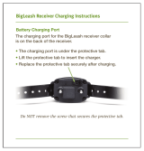
3. Charge Battery
Fully charge the rechargeable Lithium Ion battery by connecting the unit to one of Listen Technologies
charging options.
a. LA-380 Intelligent 12-Unit Charging/Carrying Case
b. LA-381 Intelligent 12-Unit Charging Tray
c. LA-421 1-Port USB Charger ( comes with cable)
d. LA-423 4-Port USB Charger (comes with 4 cables)
e. LA-422 USB to Micro USB cable (Connects iDSP™ receiver to any standard USB port)
When connected to a charging option the OLED status display will show the battery charge Icon
momentarily and the status LED next to the power button will begin to ash indicating that the unit
is charging.
When the unit reaches 100% charged the status LED next to the power button will stop ashing and
will be solid.
Pull the tab to activate
the internal battery
OLED Display:
Charging Icon when
rst connected to a
charging source
Indicated Unit #,
Charge % and Channel
Assignment when
removed for charging
Status LED:
Flashes during charging
Solid when charge is
complete

LR-5200 RECEIVER MANUAL
l
PAGE 9
4. Connect Earphone
Using The Earphone/Neck Loop Lan-
yard
Connect the Listen Intelligent ear phone/
neck loop lanyard to the
two 3.5 mm output jacks on the
unit. Then connect the short cable
ear speaker or headphones to
the 3.5mm output jack on the
lanyard. The lanyard neck loop
is placed over the head and
worn as a necklace.
This is the preferred method of
wearing the receiver for best
performance!
For T-coil compatible hearing aid use
simply disconnect the ear speaker or
headset from the ear phone/neck
loop lanyard.
Using The 3.5mm Earphone Extension Cable
If the receiver is to be clipped to a belt, waistband or inside a pocket a long extension cable is used. Con-
nect the extension cable to the ear speaker, headset or earphones, then connect the extension cable into
one of the 3.5 mm output jacks on top of the receiver.
Headset
Ear Phone/
Neck Loop
Lanyard
Ear
Speaker
Earbuds
Headset
Ear
Speaker
Extension
Cable
Earbuds

PAGE 10
l
LR-5200 RECEIVER MANUAL
5. Turn the Unit On
Press and hold the Power Button for 1 second to turn the receiver on, the unit display will show the unit ID,
battery status and the current channel. Each item will be displayed and then the display will turn o.
To view the unit ID, battery status or channel while the unit is powered, momentarily press the power
button. To turn the receiver o, press and hold the power button for 3 seconds.
6. Programmable Channel Select (Listen Button)
The main advantage of the LR-5200 Receiver is the functionality of the programmable Listen Button. The
Listen Button can be programmed for Channel Select Mode, Seek Mode or be Disabled. These modes can
only be changed via the IDSP Software Suite.
Note: In order for the LR-5200 to receive audio it must be on the same channel as a transmitter in
the facility. 72 MHz receivers operate on 17 wide band channels and 40 narrow band channels. Channels
represented by letters on the display (i.e. A) are wideband channels: channels represented by numbers
are narrowband channels. Listen recommends the use of wide band channels for a much higher quality
listening experience.
216 MHz receivers operate on 19 wide band
channels and 38 narrow band channels. Channel
numbers starting with a “2” are wide band; channels
beginning with a “1” or “3” are narrow band channels.
It is important to choose channels that are free
from interference to achieve proper operation
of your Listen equipment. This process is trial
and error. Before turning on the transmitter,
listen for interference on the available channels.
Choose channels with the least amount of
interference. If you are using multiple channels
follow this process:
OLED Display:
Indicates Unit #,
Charge %
and Channel
Assignment
when power
button is pressed
#123
Power Button:
Press and hold for
1 second to turn
on, press and hold
for 3 seconds to
turn o
1. Channel Select:
(Listen Button)
CH 1

LR-5200 RECEIVER MANUAL
l
PAGE 11
Same Space: If you are using transmitters in the same space, the most number of channels that will work
simultaneously is six wide band channels or 8 narrow band channels at 72 MHz, three wide band channels
or 5 narrow band channels at 216 MHz. With all of the transmitters o, listen for interference on all the wide
band channels via the headphone jack. Using the frequency compatibility tables on pages 21-22, eliminate
any channels that have noticeable interference. Now choose the channels with the widest channel spacing.
It is recommended that adjacent channels be spaced at least 300 KHz. If there is no interference the fol-
lowing channels are recommended: A, C, E, I, J, and H (wide band) or 1, 5, 10, 16, 21, 24, 31, and 35 (narrow
band) for 72 MHz and 2A, 2K, and 2V (wide band) or 1A, 1C, 1F, 1N, and 1V (narrow band)
Distributed Spacing: If you are using transmitters that are spread out over space, you can achieve more
simultaneous broadcast channels. However, it is critical that your receiver(s) be located as close to its trans-
mitter as possible. You can use adjacent channels (see frequency compatibility tables on pages 21-22) in this
case as long as the adjacent channel transmitter is at least 50% further away from the receiver as its trans-
mitter. Example: The transmitter for the receiver on channel E is 100 feet from the receiver. The adjacent
channel transmitter on channel D should be at least 150 feet away.
Channel Select Mode
The Listen Button on your receiver has been programmed from the factory for Channel Select Mode. This
mode is especially useful for applications where users are required to select between active channels (such
as language interpretation or multiple classrooms), and you don’t want them to have to go through all avail-
able channels to nd the appropriate channel. In this mode the button can be programmed to increment
only through the desired active channels in your facility and lock out all the other unused channels.
In this mode when the Listen Button is pressed the unit will increment through the channel list to the next
programmed channel. For example if there are three channels programmed (English, Spanish and Ger-
man) and the unit is on the English and the button is pressed the unit will switch to Spanish. If the button is
pressed again the unit will switch to German and an additional press will take the unit back to English again.
There are two modes to customize the channel list for the Listen Button. The two modes are Automatic
Channel Selection and Manual Channel Selection. These modes can be programmed using the unit or via
the IDSP Software Suite.
Your Listen receiver has been shipped to you with the Automatic Channel Selection, Auto 2 (channels E and
A) enabled for 72MHz or (channels 2C and 2V) enabled for 216 MHz.

PAGE 12
l
LR-5200 RECEIVER MANUAL
1. Automatic Channel Selection
In the Automatic Channel Selection mode the user decides how many channels of audio are to be
received by the unit. In this mode the unit automatically selects the channels that can be used together
simultaneously in a given space. The unit is defaulted to Auto 2. The max number of channels is 8 for 72
MHz and 5 for 216 MHz.
72 MHz
Auto 1 (Channel E)
Auto 2 (Channels E, A)
Auto 3 (Channels E, A, H)
Auto 4 (Channels E, A, H, I)
Auto 5 (Channels E, A, H, I, J)
Auto 6 (Channels E, A, H, I, J, C)
Auto 7 (Channels 1, 5, 10, 16, 21, 24, 31)
Auto 8 (Channels 1, 5, 10, 16, 21, 24, 31, 35)
The user selects the number of channels by using the following sequence:
Simultaneously press and hold the UP and POWER button for 3 seconds. The unit will display “Auto 2”
on the display. Press the UP/DOWN button for the number of desired channels. Momentarily press the
POWER button to save the setting or after 5 seconds of no activity the setting is saved and the unit
returns to normal operation.
Or use the IDSP Software Suite for set up!
2. Manual Channel Selection
In the Manual Channel Selection mode the user decides specically which channels are to be received
by the unit. It is recommended that adjacent channels be spaced at least 300 KHz apart if being used
simultaneously.
The user selects these channels by using the following sequence:
1. Auto
Select Mode:
Press and hold
the Power and
Up button
simultaneously
for 3 seconds
2. Scroll Up/Down:
Use the up or
down button to
scroll through
available options
Auto 2
3. Save/Exit:
Press power button
to save and exit.
216 MHz
Auto 1 (Channel 2C)
Auto 2 (Channels 2C, 2V)
Auto 3 (Channels 2A, 2C, 2V)
Auto 4 (Channels 1A, 1F, 1N, 1V)
Auto 4 (Channels 1A, 1C, 1F, 1N, 1V)

LR-5200 RECEIVER MANUAL
l
PAGE 13
Simultaneously press and Hold the DOWN and POWER button for 3 seconds. The unit will display “Manual”
on the display for 3 second and then displays the current channel. If the channel is used (meaning the Listen
Button can select it) the channel will be solid; if not it will ash. Press the LISTEN button for each selected
channel to change between “used” (solid) and “not used” (ashing). Press the UP/DOWN button to scroll through
all available channels. Momentarily press the POWER button to save and end or after 5 seconds of no activity
the setting are saved and the unit returns to normal operation.
Note: The IDSP Software Suite can also be used for set up!
Channel Select Mode
Once the channels have been selected via the Automatic Channel Selection or the Manual Channel Selection
modes a quick change to a specic channel can be made easily. This can be accomplished by the following
process:
Select the channel to be changed via the Listen Button. Press and hold the volume up and down buttons
simultaneously for 5 seconds. The current channel will begin to ash on the display.
Use the volume up or down button to scroll through the available channels. Once the desired channel
is located momentarily press the power button to save and exit the channel select mode or if no button
is pressed for 5 seconds then the selected channel will be saved and the unit will exit the channel select
mode. See page 21 for complete channel selection information.
Seek Mode
Seek Mode is another way to nd and active channel in a venue. In the Seek Mode with a press of the
Listen Button the unit searches for and locks onto the next active channel in the list of available channels.
This mode is useful when users are moving from room to room or may not know which channel to select.
In this mode it is possible that the unit will mistake interference for a real broadcast signal. If you
get interference, press the Seek Button again. The unit may also stop on a channel that is close to the
actual broadcast channel if in the available channel list, in which case the channel will sound noisy
or distorted. Simply press Seek again until you nd the clearest operating channel.
1. Manual
Select Mode:
Press and hold
the Power and
Down button
simultaneously
for 3 seconds
2. Scroll Up/Down:
Use the up or down button to
scroll through available channels
3. Channel Select:
(Listen Button)
Push Listen button to select /de-select the channel
CH E
4. Save/Exit:
Press power button
to save and exit.
3. Save/Exit
Press power button to save
and exit
1. Channel Select Mode
Press and hold Up and Down
button simultaneously for 5
seconds
2. Scroll Up/Down
Use the Up or Down
button to scroll
through available
channels
CH E

PAGE 14
l
LR-5200 RECEIVER MANUAL
OLED Display:
A closed lock
will display.
Lock Mode:
Press and hold the
Listen button for
5 seconds.
OLED Display:
An open lock
will display.
Un-Lock Mode:
Press and hold the
Listen button for
5 seconds.
Disabled
When in the disabled mode the Listen Button has no function.
Listen Button Lock
Once an active channel is found it is sometimes desirable to lock the unit onto the currently tuned
channel and not allow the user to make any channel changes. This can be accomplished by pressing
and holding the listen button for 5 seconds. When the unit enters locked mode the unit will show the
locked symbol on the display for 3 second. When locked, each time the Listen Button is pressed the unit
will show the locked symbol on the display for 3 seconds.
To unlock the unit simply press and hold the Listen button for 5 seconds. When the unit is unlocked the
unit will show the unlocked symbol on the display.

LR-5200 RECEIVER MANUAL
l
PAGE 15
Adjust Volume
Adjust the listening volume to a comfortable listening level via the volume up/down buttons.
If the volume is adjusted while there is no audio present the unit will output a momentary tone each time
the button is pressed allowing the user to gauge and adjust the audio level to a comfortable listening level.
The volume level will be displayed for 3 seconds and then the display will turn o.
Note: To protect the users hearing, at power up the receiver will automatically reset to a 25% volume level. Put
on a headset and then adjust the volume to a comfortable listening level.
OLED:
Indicates the
level in a % of
maximum level
Volume Up/Down
Use the volume up
or down to raise/
lower volume
50%

PAGE 16
l
LR-5200 RECEIVER MANUAL
Battery & Belt Clip
Low Battery Indication
When the unit detects a low battery condition it will cause the status LED to ash slowly indicating that the
unit needs to be charged. When the light begins to ash the unit has approximately 30 minutes of receiver
use before the unit will turn o. Press and release the power button and the battery charge % will be dis-
played on the OLED screen temporarily.
Belt Clip Installation/Removal
To remove belt clip, remove screw and pull belt clip from unit. To install place belt clip in place and insert
screw.
Status LED:
Begins to ash
when receiver
has less than an
estimated 30
minute use left
on the charge
OLED Display:
Press the Power
button to get the
status of
the battery
charge life
OLED Indicates a
% of charge
100%
Belt Clip Screw:

LR-5200 RECEIVER MANUAL
l
PAGE 17
Accessing Battery Compartment
To access the battery compartment simply remove the belt clip and battery door by pulling down and out
on the battery door locking tab. Note: The product labeling information can be found behind the battery and
includes the product model number, description, serial number, contact information and compliance statement.
Reset to Factory Default Settings
The unit can be returned to its factory default settings at any time by following steps:
1. Turn the unit o
2. Press and hold down the volume down button while pressing and holding the power button
for 1 second to turn the unit on
3. Continue to hold down the volume down button while the unit powers on. The OLED display
will show the Unit #, Charge Level %, Channel Selection and end with “Reset?”
4. Release the volume down button when Reset is displayed on the OLED display.
5. Press the power button to conrm default is desired. Once pressed the unit will display
“Defaulted” on the OLED display. The unit has now returned to the factory default state
6. If 5 seconds lapses before the power button is the pressed, the unit will time out and the unit
will not reset to the factory default settings
Door
locking
tab
Battery door

PAGE 18
l
LR-5200 RECEIVER MANUAL
Advanced Program Features and Listen’s iDSP Software Suite
To manage the advanced program features on any of the iDSP™ receivers a windows based User
Interface (UI) software is required.
This software is available free of charge
from Listen Technologies. To download
the software log onto http://www.listen-
tech.com/support/software/idsp-soft-
ware-suite/ and follow the instructions.
With the UI software, direct communication
is provided via the Micro USB connection
on the receiver. Once connected the UI
software provides setup and adjustment of
the following functions of the LR-5200 receiver.
Note: A help le for the UI software is included
with the download and will provide detailed
instructions for set up and management of
all the advanced program features of the
LR-5200 receiver.
Super Quiet Mode
To reduce background noise and increase the audio quality, Listen oers a noise reduction technology
called Listen SQ™. Only Listen *transmitters and receivers have SQ™ available, both the transmitter and
receiver must have SQ™ activated to achieve the improved sound quality performance. This
LR-4200 receiver has been shipped to you with the SQ™ feature enabled.
SQ™ Summary:
Improves noise performance by at least 20 dB
SQ must be enabled for both the transmitter and receivers
SQ™ is NOT Squelch
SQ™ is NOT compatible with other manufactures’ products
SQ™ can be disabled to permit operation with early Listen products or other
manufactures, products
Note: SQ™ is not available on some of the early Listen transmitters. Please contact Listen’s Technical Support team to nd out if your
existing transmitter has this feature available.
Note: If you are planning to use this product with older Listen systems that do not employ SQ™ or
another manufactures transmitter The SQ™ mode should disabled on this receiver. Refer to the
manual supplied with the downloaded Listen UI software for details on how to manage the SQ™ Mode on this
receiver.

LR-5200 RECEIVER MANUAL
l
PAGE 19
Squelch
The purpose of squelch is to mute the audio output of the receiver when the signal from the
transmitter is turned o or the level is too weak to be received. Without squelch radio noise will
be heard in the earphone. The squelch on the receiver can be adjusted to mute the audio at
dierent RF signal strengths. There are 20 squelch settings. The lowest squelch setting (no squelch)
is “0” and the tightest squelch setting is “20”. Your Listen receiver has been shipped to you with the
squelch setting of 3.
Useful as follows:
• To ensure that users don’t hear transmissions from other transmitters, set the squelch setting to
the highest level that doesn’t squelch the receiver in the dened listening area
• If the receiver is to close to the transmitter (i.e. in a classroom), set the squelch high enough so that
when the transmitter is turned o it immediately squelches the audio on the receiver and trans-
mitters in other rooms will not be heard
• In an area that has a lot of broadcast inference, adjust the squelch setting to a higher setting to
ensure the interference is not picked by the receiver
• For the maximum amount of range, consider setting the squelch setting to a low level (0, 1 or 2).
This expands the range but could allow interference from other transmitters when operating far
distances from the primary transmitter
Basic Channels and Expanded Channels Modes
Your Listen receiver has been shipped with the Basic Channel Mode enabled.
In the default Basic Channel Mode, only the wide band channels are available for selection. If the channel
desired is not available in Basic Channel Mode, the receiver will need to be set to the Expanded Channel
Mode. In Expanded Channel Mode all wide band and narrow band are available for selection.
Channel Labels
The channel labels are displayed on the OLED status screen. The default is the channel number the re-
ceiver has been programmed to receive, i.e. “CH-E”. Customization of this display can be created to better
identify the type of audio, for example CH-E could be changed to display “Spanish” if the receiver is used
for language translation.
Auto Power Mode
The auto power mode will automatically power the receiver on when the unit is removed from
the charging device, displaying the unit ID, battery status and the active channel. When the unit is
returned to the charging device the unit will automatically turn o and resume charging operation. Your
Listen receiver has been shipped to you with the Auto Power Mode enabled.

PAGE 20
l
LR-5200 RECEIVER MANUAL
Unit ID
The unit ID number provides a unique identication for each receiver that is displayed on the OLED status
screen. This can be any 3 digit number between 000 and 999. The unit ID allows venues to track individual
units and for easy dispensing and inventory control. Your Listen receiver has been shipped to you with a
Unit ID of 000.
Brightness Control
The Brightness Control adjusts the level of brightness of the OLED display. There are four settings Auto,
Bright, Dim and Disabled. In the Auto mode the unit uses an internal light sensor and automatically dims
the display when the light level is below approximately 10 Lux. In the Bright, Dim or Disabled mode the
unit disables the light sensor and leaves the OLED in the selected Bright or Dim state. In the disabled
mode the unit disables the display from lighting during normal operation except for the power on
sequence or when the power button is momentarily pressed to check status. The receiver is shipped with
the Auto Brightness Control Mode enabled.
Jack Sense
The jack sense mode when enabled will automatically turn the receiver on when a headset is inserted into
the 3.5 mm output jack on the receiver. The receiver will automatically turn o after 60 seconds when the
headset is removed from the 3.5 mm output jack. Your listen receiver has been shipped to you with the
Jack Sense Mode disabled.
Note: If Jack Sense is on and Auto Power is on, the receiver will ignore jack sense while on the charger.
Unit Information
When a unit is connected to the conguration software the software extracts specic information from the
unit and displays it for the user. This information includes the model number, frequency, Serial Number
and Firmware Version.
Reset to Factory Defaults
The unit can be returned to the factory default settings.
Firmware Update
The rmware update function will check via the internet to see if a rmware update is available for
the receiver.
/