Vetus 1000/1500 VW-VWC-VWLP-VWCLP User manual
- Type
- User manual

1000 & 1500 Windlass
Manual

VETUS–MAXWELL APAC Ltd
Copyright Vetus-Maxwell APAC Ltd. All rights
reserved.
Vetus-Maxwell APAC Ltd reserves the right to make
engineering refinements on all products without notice.
Always consult manual supplied with product as details
may have been revised.
Illustrations and specifications are not binding as to
detail.
P103103 Rev.6.00 12/10/17

Vetus-Maxwell APAC Ltd 1000 1500 Windlass 1
Table of Contents
Preliminary Information .............................................................................................................. 2
Introduction ............................................................................................................................... 2
Components ............................................................................................................................. 2
Important Safety Information .................................................................................................... 3
Parts of the Windlass ............................................................................................................... 4
Parts of the Gearbox ................................................................................................................ 8
Ordering Spare Parts ................................................................................................................ 8
Chain Selection Guide .............................................................................................................. 9
Installation .................................................................................................................................. 10
General Requirements ........................................................................................................... 10
Installation Instructions ........................................................................................................... 11
Wiring Instructions .................................................................................................................. 14
Operation .................................................................................................................................... 19
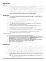
Anchoring Tips ........................................................................................................................ 19
Lowering the Anchor ............................................................................................................... 19
Raising the Anchor ................................................................................................................. 19
Free falling the Anchor ........................................................................................................... 20
Raising the Anchor Manually .................................................................................................. 20
Using the Warping Drum ........................................................................................................ 20
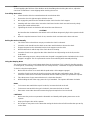
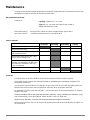
Maintenance ............................................................................................................................... 23
Trouble Shooting Guide ............................................................................................................ 25
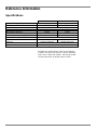
Reference Information............................................................................................................... 26
Specifications ......................................................................................................................... 26
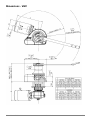
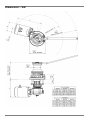
Dimensions ............................................................................................................................. 27
Typical Greasing Instructions ………………………………………………………………………28
Additional Resources
The following resources are included at the back of this manual:
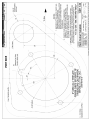
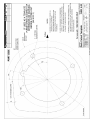
Deck Cutout Details
Warranty Form
Note: For your nearest retailer, service agent or representative please refer to our website
www.maxwellmarine.com

2 1000 1500 Windlass Vetus-Maxwell APAC Ltd
Preliminary Information
Introduction
Congratulations on your purchase of a Maxwell windlass. Please read these instructions carefully to
enable you to correctly install and maintain the windlass for years of trouble-free operation.
Note
Failure to follow the correct installation, operation or maintenance instructions will jeopardise your safety
and could invalidate the warranty.
Components
In addition to this instruction manual, the following components may be included with the windlass:
Windlass
Remote up/down control panel
Circuit breaker/isolator panel
12V or 24V reversing solenoid
Clutch Lever
Deckplate gasket
Motor Bolt Kit
Template (At rear of manual)
Small parts:
Nuts
Flat washer
Spring washer

Vetus-Maxwell APAC Ltd 1000 1500 Windlass 3
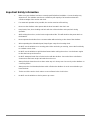
Important Safety Information
Make sure your windlass has been correctly specified before installation - Personal safety may
depend on it. The windlass must have a maximum pull capacity of at least three times the
combined weight of the anchor and chain.
For automatic operation to be possible, the anchor must be self launching.
Never use the windlass under power with the lever inserted in the clutch nut.
Keep hands, feet, loose clothing and hair well clear of the windlass and rope/chain during
operation.
While raising the anchor, run the boat's engine above idle. This will minimise the power drain on
the batteries.
Never operate the windlass from a remote station without having a clear view of the windlass.
When operating the chainwheel pawl, keep fingers away from incoming chain.
Do NOT use the windlass as a mooring point. When anchoring or mooring, secure the line directly
to a bollard or deck cleat.
Do NOT use the windlass to pull the boat forward when raising the anchor. Use the boat's engine
to drive the boat up to the anchor.
Do NOT attempt to break free a fouled anchor with the windlass. Secure the line to a bollard or
cleat and use the boat's engine to break the anchor out.
Always firmly tie down the anchor when under way or in heavy seas. Do not rely on the windlass as
a securing device.
Always turn the circuit breaker/isolator switch off when the windlass is not in use and before you
leave the boat.
Tie the end of the anchor chain rode to a secure fixture in the chain locker.
Do NOT use the windlass to haul a person up a mast.

4 1000 1500 Windlass Vetus-Maxwell APAC Ltd
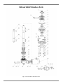
VW and VWLP Windlass Parts
Fig 1: VW and VWLP Windlass Parts

Vetus-Maxwell APAC Ltd 1000 1500 Windlass 5
VW and VWLP Windlass Parts
Item No.
Component description
Qty
Part to order
Includes items
1
Cap
1
3465
2
Label - 1000
1
6424
Label - 1500
1
6425
3
Screw - 3/8" x 1"
1
P101615
1,3,4,7,10,15,25(x2)
4
Washer
1
P101615
1,3,4,7,10,15,25(x2)
5
Clutch Nut
1
*P101621 or P101622
1,2,5
6
Drum - VWC
1
7502
7
Circlip
1
P101615
1,3,4,7,10,15,25(x2)
8
Clutch Cone
2
P101623
8(x2)
9
Chainwheel
1
3173
10
"V" Ring Seal
1
P101615
1,3,4,7,10,15,25(x2)
11
Retaining Collar
1
**P101664 or P101665 or P101666
11,28,29
12
Emergency Crank Lever
1
P20044
13
Pin - Pawl
1
P101620
13,14,15
14
Pawl
1
P101620
13,14,15
15
Washer
1
P101615
1,3,4,7,10,15,25(x2)
16
Cheese Head Screw - M8 x 16
2
P101626
16(x2),17(x1)
17
Stripper
1
P101626
16(x2),17(x1)
18
Deckplate
1
**P101627 or P101628 or P101629
11,18,20(x4),21(x4),22(x4),23(x4),28,29
19
Gasket
1
3474
20
Stud - 50TDC
4
P101612
20,21,22,23
Stud - 100TDC
4
P101613
20,21,22,23
Stud - 150TDC
4
P101614
20,21,22,23
21
Washer
4
**P101612 or P101613 or P101614
20,21,22,23
22
Spring Washer - 3/8"
4
**P101612 or P101613 or P101614
20,21,22,23
23
Nut - 3/8"
4
**P101612 or P101613 or P101614
20,21,22,23
24
Shaft - VW - 50TDC
1
6152
Shaft - VW - 100TDC
1
6151
Shaft - VW - 150TDC
1
6150
Shaft - VWLP - 50TDC
1
6203
Shaft - VWLP - 100TDC
1
6204
Shaft - VWLP - 150TDC
1
6205
25
Key - VW
2
P101615
1,3,4,7,10,15,25(x2)
25
Key - VWLP
1
P101615
1,3,4,7,10,15,25(x2)
26
Circlip
1
P101619
26,27,38,41
27
Key
1
P101619
26,27,38,41
28
Bearing
1
**P101664 or P101665 or P101666
11,28,29
29
Spacer Tube - 50TDC
1
**P101664
11,28,29
Spacer Tube - 100TDC
1
**P101665
11,28,29
Spacer Tube - 150TDC
1
**P101666
11,28,29
30
Locknut
1
P100088
30,31,32
31
O-Ring
1
P100088
30,31,32
32
Collar
1
P100088
30,31,32
33
Gearbox - 1000 - 44:1
1
P100900
Gearbox - 1500 - 56:1
1
P102730
34
Motor - 12v - 1000W - with 1000 VWC/VWLP
1
P12072
Motor - 24v - 1000W - with 1000 VWC/VWLP
1
P12074
Motor - 12v – 1200W - with 1500 VWC/VWLP
1
P12073
Motor - 24v - 1200W - with 1500 VWC/VWLP
1
P12074
Motor - Hydraulic
1
P14366
35
Bolt - Hex Hd M8x25 - With 12 or 24V Motor
2
P12487
35(x2),36(x2),37(x2),42(x1)
36
Washer - Spring - M8 - With 12 or 24V Motor
2
P12487
35(x2),36(x2),37(x2),42(x1)
Washer - Spring - M8 - With Hydraulic Motor
2
P12488
36(x2),37(x4),39(x2),40(x2)
37
Washer - Flat - M8 - With 12 or 24V Motor
2
P12487
35(x2),36(x2),37(x2),42(x1)
Washer - Flat - M8 - With Hydraulic Motor
4
P12488
36(x2),37(x4),39(x2),40(x2)
38
Clip
1
P101619
26,27,38,41
39
Bolt - Hex Hd M8x30 - With Hydraulic Motor
2
P12488
36(x2),37(x4),39(x2),40(x2)
40
Nut - M8 - With Hydraulic Motor
2
P12488
36(x2),37(x4),39(x2),40(x2)
41
Tension Pin
1
P101619
26,27,38,41
42
O-Ring
1
P12487
35(x2),36(x2),37(x2),42(x1)
**P101621 = 1000, P101622 = 1500
**P101627 = 50mm TDC, P101628 = 100mm TDC, P101629 = 150mm TDC
**P101612 = 50mm TDC, P101613 = 100mm TDC, P101614 = 150mm TDC
**P101664 = 50mm TDC, P101665 = 100mm TDC, P101666 = 150mm TDC

6 1000 1500 Windlass Vetus-Maxwell APAC Ltd
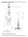
VWC and VWCLP Windlass Parts
Fig 2: VWC and VWCLP Windlass Parts

Vetus-Maxwell APAC Ltd 1000 1500 Windlass 7
VWC and VWCLP Windlass Parts List
Item no.
Component description
Qty
Part/Kit to order
Kit items
1
Cap
1
3465
2
Label - 1000 VWC VWCLP
1
6424
Label - 1500 VWC VWCLP
1
6425
3
Screw - 3/8" x 1"
1
P101615
1,3,4,7,10,15,27(x2)
4
Washer
1
P101615
1,3,4,7,10,15,27(x2)
5
Clutch Nut
1
*P101621 or P101622
1,2,5
6
Drum - VWC
1
7502
7
Circlip
1
P101615
1,3,4,7,10,15,27(x2)
8
Clutch Cone
2
P101623
8(x2)
9
Chainwheel
1
3173
10
"V" Ring Seal
1
P101615
1,3,4,7,10,15,27(x2)
11
Retaining Collar
1
**P101664 or P101665 or P101666
11,31,32
12
Plug
1
**P101616 or P101617 or P101618
11,12,21,23(x4),24(x4),25(x4),26(x4),31,32
13
Pin - Pawl
1
P101620
13,14,15
14
Pawl
1
P101620
13,14,15
15
Washer
1
P101615
1,3,4,9,14,26(x2)
16
Cap Screw - M8 x 35
1
P101600
16(x2),17(x2),18(x2),19,20
17
Spring Washer - M8
1
P101600
16(x2),17(x2),18(x2),19,20
18
Flat Washer - M8
1
P101600
16(x2),17(x2),18(x2),19,20
19
Chain Cover
1
P101600
16(x2),17(x2),18(x2),19,20
20
Stripper
1
P101600
16(x2),17(x2),18(x2),19,20
21
Deckplate
1
**P101616 or P101617 or P101618
11,12,21,23(x4),24(x4),25(x4),26(x4),31,32
22
Gasket
1
3473
23
Stud - 50TDC
4
P101612
23,24,25,26
Stud - 100TDC
4
P101613
23,24,25,26
Stud - 150TDC
4
P101614
23,24,25,26
24
Washer
1
**P101612 or P101613 or P101614
23,24,25,26
25
Spring Washer - 3/8"
4
**P101612 or P101613 or P101614
23,24,25,26
26
Nut - 3/8"
1
**P101612 or P101613 or P101614
23,24,25,26
27
Key - VWC
2
P101615
1,3,4,7,10,15,27(x2)
Key - VWCLP
1
P101615
1,3,4,7,10,15,27(x2)
28
Shaft - VWC - 50TDC
1
6152
Shaft - VWC - 100TDC
1
6151
Shaft - VWC - 150TDC
1
6150
Shaft - VWCLP - 50TDC
1
6203
Shaft - VWCLP - 100TDC
1
6204
Shaft - VWCLP - 150TDC
1
6205
29
Circlip
1
P101619
29,30,37,44
30
Key
1
P101619
29,30,37,44
31
Bearing
1
**P101664 or P101665 or P101666
11,31,32
32
Spacer Tube - 50TDC
1
**P101664
11,31,32
Spacer Tube - 100TDC
1
**P101665
11,31,32
Spacer Tube - 150TDC
1
**P101666
11,31,32
33
Locknut
1
P100088
33,34,35
34
O-Ring
1
P100088
33,34,35
35
Collar
1
P100088
33,34,35
36
Gearbox - 1000 - 44:1
1
P100900
Gearbox - 1500 - 56:1
1
P102730
37
Clip
1
P101619
29,30,37,44
38
Washer - Flat - M8 - With 12 or 24V Motor
2
P12487
38(x2),39(x2),40(x2),45(x1)
Washer - Flat - M8 - With Hydraulic Motor
2
P12488
38(x2),39(x4),41(x2),42(x2)
39
Washer - Spring - M8 - With 12 or 24V Motor
2
P12487
38(x2),39(x2),40(x2),45(x1)
Washer - Spring - M8 - With Hydraulic Motor
4
P12488
38(x2),39(x4),41(x2),42(x2)
40
Bolt - Hex Hd M8x25 - With 12 or 24V Motor
2
P12487
38(x2),39(x2),40(x2),45(x1)
41
Bolt - Hex Hd M8x30 - With Hydraulic Motor
2
P12488
38(x2),39(x4),41(x2),42(x2)
42
Nut - M8 - With Hydraulic Motor
2
P12488
38(x2),39(x4),41(x2),42(x2)
43
Motor - 12v - 1000W Motor - with 1000 VWC/VWLP
1
P12072
Motor - 24v - 1000W Motor - with 1000 VWC/VWLP
1
P12074
Motor - 12v - 1200W Motor - with 1500 VWC/VWLP
1
P12073
Motor - 24v - 1200W Motor - with 1500 VWC/VWLP
1
P12074
Motor - Hydraulic
1
P14366
44
Tension Pin
1
P101619
29,30,37,44
45
O-Ring
1
P12487
38(x2),39(x2),40(x2),45(x1)
46
Emergency Crank Lever
1
P20044
*P101621 = 1000 VWC VWCLP, P101622 = 1500 VWC VWCLP
**P101616 = 50mm TDC, P101617 = 100mm TDC, P101618 = 150mm TDC
**P101612 = 50mm TDC, P101613 = 100mm TDC, P101614 = 150mm TDC
**P101664 = 50mm TDC, P101665 = 100mm TDC, P101666 = 150mm TDC

8 1000 1500 Windlass Vetus-Maxwell APAC Ltd
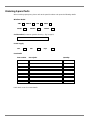
Ordering Spare Parts
When ordering spare parts, please refer to the parts list above and quote the following details.
Windlass Model
VWC
VWCLP
VW
VWLP
50TDC
100TDC
150TDC
Serial number (located on gearbox housing – Fig 3 Page 8)
Power supply
12V
24V
Hyd
Part details
Part number
Description
Quantity
Refer back cover for contact details.

Vetus-Maxwell APAC Ltd 1000 1500 Windlass 9
Chain Selection
THE MAXWELL WINDLASSES ARE DESIGNED FOR ALL CHAIN SYSTEMS USING: 6-10mm (1/4” –
3/8”) short link
Your Windlass should have a rating of approximately 3 times total combined weight of the anchor and
chain.
The ground tackle should have been selected taking into account:
a) Boat size, displacement and windage.
b) Conditions of operation such as maximum depth of water, type of bottom and weather conditions.
c) Holding power and size of anchor, taking special note of the manufacturers’ recommendations.
CORRECT FIT OF CHAIN TO CHAINWHEEL IS ESSENTIAL FOR THE WINDLASS TO OPERATE
PROPERLY.
A range of chainwheels is available to suit your windlass.
The correct fit can only be guaranteed where a standard chain known to us is used. Alternatively a
450mm (18”) or 12 links (whichever is longer) sample must be forwarded to us to match fit. Where
patterns to suit are not held by us we are able to manufacture to instructions and reserve the right to
charge cost thereof.
THE WINDLASS SHOULD BE USED IN CONJUNCTION WITH A MAXWELL CHAIN STOPPER, OR
SNUBBER, OF THE APPROPRIATE SIZE.

10 1000 1500 Windlass Vetus-Maxwell APAC Ltd
Installation
General Requirements
Foredeck layout
Make sure that the area of deck between the windlass and the bow roller is clear of obstructions.
The bow roller should have a central groove suitable for the chain size.
Use a chain guide if necessary to prevent the chain from running against the deckplate and potentially
causing damage to the windlass.
Anchor and chain considerations
When purchasing an anchor, make sure it fits into the bow roller and is self-launching.
Use a swivel between the anchor and the chain to prevent the line from twisting as the anchor is raised or
lowered.
To prevent build up of chain on deck causing possible damage, the bow roller must allow the anchor to
free fall immediately when the anchor is deployed.
Make sure that at least three links of chain are exposed when the anchor is docked.
The chain must gravity feed into the locker. If the chain outlet cannot be positioned directly over the
locker, heavy wall flexible plastic pipe can be used to direct the chain to the required area. It is important
that the chain slips through easily, completely unaided. It may be necessary to provide the pipe with a
bell mouth or to bell mouth the entrance to the chain outlet from the locker to assist the free flow of the
chain from the locker.
NOTE: Make sure you securely fasten the end of the chain to the boat.
Required clearances
Ideally the outlet for the chain should be directly over the chain locker. The chain should have at least
300mm (1ft) clear fall to allow the chain to straighten before passing through the windlass.
Position the windlass clear of pulpit, lifelines and bulwark so that there is room to swing the Clutch Lever.
Refer to Figures on page 27 and 28 for overall dimensions
The chain locker must be of such a size that the chain will heap up and feed out naturally without fouling
the windlass motor.
Allow access for conveniently connecting the supply lines under deck after the windlass is bolted in
position.
It should be noted that the gearbox can be indexed at different positions in relation to the deck plate. Be
sure to select the most convenient position and allow for the best run for the chain to clear the motor.
Aligning the windlass
“UP” is the clockwise rotation when looking down on the windlass.
The windlass must be positioned to allow the chain to have a clear run from the bow roller to the
chainwheel.
The deck plate should be mounted pointing in the direction of the incoming chain and with the left hand
side parallel to the line of the incoming chain. This arrangement allows the chain to have maximum
engagement with the chainwheel.
The bow roller should have a vertical groove to suit the profile of the chain. This will align the chain so
that it enters the chainwheel without twisting.

Vetus-Maxwell APAC Ltd 1000 1500 Windlass 11
Installation Instructions
Before you start
Before installing the windlass, identify any bulkheads, wiring or piping under the deck. This may
determine where the windlass can be positioned. Ensure the deck is flat, if not; a plinth will be required to
ensure the windlass sits on a flat surface.
If the windlass is installed horizontally, on a bulwark (mainly VW type), make sure that the gearbox is
installed with worm on the lower side to ensure good lubrication of the gears. The stripper should also be
positioned at the lowest end of the deckplate
Deck thickness
It is imperative that the deck and under-deck pad (not supplied) are of sufficient thickness and structural
strength to support the loads imposed on or by the windlass.
An under-deck pad should spread the load as widely as possible.
Preventing electrolysis
For aluminium boats, it is essential that the deckplate be insulated from the deck with a non-conductive
gasket (not supplied), that the mounting studs pass through insulators (not supplied), and that the under-
deck fastenings are insulated from the deck with fibre washers (not supplied).
It is also important that the anchor and chain are insulated from the hull, including rubber lining the chain
locker and insulating the fixing for the end of the rode to the hull.
Without these precautions, severe electrolysis can occur.
Because the motor is of the isolated earth type, it is not necessary to separately earth the windlass.
Locating the chain stopper
The chain stopper should be positioned and aligned in a convenient position between the windlass and
the bow roller, so that it clears the anchor stock. The chain should pass through the stopper without
being deflected.
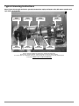
Installation procedure
** ATTENTION**
Please note, when installing winch and in particular the chain wheel. The shaft and bronze clutch cones
MUST be coated in grease during assembly. See “Typical Greasing Instructions” on Pg 30.
1. Use the Deck Cutout Details drawing as a guide for marking and cutting the holes.
Tip: On GRP boats, running the drill in reverse first will reduce chipping of the gel coat.
Using hole saws, cut the holes for the spacer tube and chain pipe.
2. On GRP or wooden decks, seal the edges of the holes with epoxy to avoid ingress of moisture.
3. Remove the gearbox from the spacer tube by undoing the Locknut. With gearbox held horizontally,
check that oil is showing half way up the sight glass. If necessary, top up with SAE 90 (Shell
Omala 320, Castrol Alpha SP320 or equivalent), by removing the sight glass and adding the
required amount. DO NOT OVER FILL!
4. Use the gasket supplied to seal the windlass to the deck. For aluminium boats fit a non-conductive
gasket to insulate the deckplate from the deck to prevent electrolysis.

12 1000 1500 Windlass Vetus-Maxwell APAC Ltd
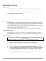
5.
Fasten the windlass to the deck using the nuts and washers
supplied. Tighten the nuts progressively and evenly. Do NOT use
power tools. Make sure the installation is firm, but do not over tighten
the nuts.
6.
Smear a coating of grease on the shaft and spacer tube. Fit the
gearbox/motor assembly to the bottom of the spacer tube. Orientate
the motor away from the incoming chain and then tighten the plastic
locknut by hand.
NOTE: If the unit is going to be mounted in such a way, that it may
be tilted, ensure the drainage slot on the gearbox is at the lowest
point to prevent excess water etc. sitting around the seals.
Drainage Slot
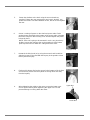
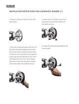
7.
Rotate the shaft by hand (or by using the manual crank handle) to
align the keyway in the shaft with the keyway in the gearbox. Insert
the key into the keyway.
8.
Fit the quick-release clip into the groove in the bottom of the shaft to
secure the key. Make sure the eyelets are facing down and away
from the keyway.
9.
When tightening the cables to the motor, ensure the lower nut is
secure against turning when tightening the upper nut. This will
prevent damage occurring within the motor.
Upper Nut
Lower Nut

Vetus-Maxwell APAC Ltd 1000 1500 Windlass 13
Assembling the chainwheel.
Refer Fig 1, page 4 for VW and VWLP Windlass and Fig 2, page 6 for VWC and VWCLP Windlass
1. With a pen knife or similar, carefully remove the Cap.
2. Remove the screw and retaining washer.
3. Remove the Clutch Nut, drum (except for low profile) and upper clutch cone.
4. Remove the stripper arm by undoing the two screws.
5. Grease the two clutch faces of the chainwheel and insert with the side that has two holes facing
upwards.
6. Assemble the components in the reverse order they were removed.
Assembling the motor.
1. Bring the motor up to the gearbox and align the roll pin with the slot in the worm.
2. Use parts from the “motor bolt kit” to assemble as per diagram on page 4.
Installing on a sloping or curved deck
Ensure that the windlass has the correct vertical alignment with the bow roller. If necessary, use a
mounting pad.
Important note to Boat Builders
Experience has shown that on long ocean deliveries as deck cargo, sulphur (from the ships exhaust and
condensation) settles and severely damages the chrome plating and stainless steel of the windlass by
breaking down the protective chrome oxide film.
We recommend, after completing installation, you spray the top works of the windlass with CRC 3097
“long life” and wrap the windlass with plastic film and tape.

14 1000 1500 Windlass Vetus-Maxwell APAC Ltd
Wiring Instructions
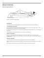
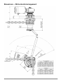
Electrical component layout
Figure 3 - Electrical component layout
Solenoid pack
The solenoid pack should be located in a dry area (not in the chain locker) close to the windlass.
Circuit breaker/isolator panel
This unit provides limited protection for the motor and full protection for the power supply cables. It also
provides the means to isolate the system from the battery.
Position the circuit breaker/isolator no further than 1.8 m (6 ft) away from the battery in an accessible and
dry location.
This equipment or equivalent is mandatory to meet USCG requirements.
Remote control panel
The remote control panel should be mounted in a convenient location (such as the bridge, helm or
cockpit) so that the operator can see the windlass. Mount and seal the panel so that the terminals project
into a dry area.
Optional footswitches
For safe operation, the footswitches must be at least 500 mm (20") from the windlass.
The below-deck part of the footswitch must be in a dry environment and the breather holes must be kept
clear.
The arrows on the footswitches should be arranged to indicate the direction of operation.
Circuit breaker/isolator
Battery
Remote control
panel
Footswitch
Solenoid pack

Vetus-Maxwell APAC Ltd 1000 1500 Windlass 15
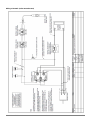
Wiring schematic (series wound motor)

16 1000 1500 Windlass Vetus-Maxwell APAC Ltd
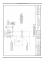
Wiring schematic (Hydraulics)

Vetus-Maxwell APAC Ltd 1000 1500 Windlass 17
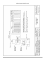
Wiring schematic (Hydraulic motor)

18 1000 1500 Windlass Vetus-Maxwell APAC Ltd
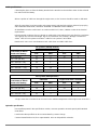
Cable specifications
Cable lengths given are from the battery terminal to the terminal on the windlass motor via the solenoid
box and back to the battery.
Where a portion of cable runs through the engine room, a size increase should be made as indicated.
After all connections have been made and system tested, seal terminals against moisture by spraying
with: CRC2043 “Plasti-Coat”, CRC3013 “Soft Seal” or CRC2049 “Clear Urethane”.
All installations must be carried out in accordance with USCG, ABYC, NMMA or other local electrical
requirements.
Recommended conductor sizes are based on cables with a heat rating of 90° and allow for a maximum
10% voltage drop over the total length. Due to circuit breaker size (135amp / 80amp) a minimum of
25mm
2
cable for 12V systems and 10mm
2
cable for 24v systems is to be fitted.
Note there is some cross over between metric cable sizes and AWG cable sizes.
12v systems (135amp breaker)
Total Cable Length
From Battery to Winch
Then Back to Battery
Cable Size
Engine room Size Correction*
mm²
AWG
mm²
AWG
Up to 10m (33’)
25
4
35
2
10m - 15m (33’-50’)
35
2
-
-
15m – 20m (50’ – 65’)
50
1
-
-
20m – 25m (65’ – 82’)
50
0
-
-
25m – 35m (82’ – 115’)
70
2/0
-
-
35m – 45m (115’ – 150’)
95
3/0
-
-
24v systems (80amp breaker)
Total Cable Length
From Battery to Winch
Then Back to Battery
Cable Size
Engine room Size Correction*
mm²
AWG
mm²
AWG
Up to 10m (33’)
10
6
6
5
10m - 15m (33’-50’)
16
4
42
1
15m – 20m (50’ – 65’)
25
4
20m – 25m (65’ – 82’)
35
3
* Engine room size correction factor is based on the ambient temperature of the engine room to be 60° C.
Hydraulic specification
Pressure/flow quoted in the specifications section, assumes operation at rated capacity with standard
motor fitted.
Levels below that specified can be accommodated by a motor change.
Contact Maxwell Marine Ltd, for a representative. who can help with this selection.
Page is loading ...
Page is loading ...
Page is loading ...
Page is loading ...
Page is loading ...
Page is loading ...
Page is loading ...
Page is loading ...
Page is loading ...
Page is loading ...
Page is loading ...
Page is loading ...
Page is loading ...
Page is loading ...
-
 1
1
-
 2
2
-
 3
3
-
 4
4
-
 5
5
-
 6
6
-
 7
7
-
 8
8
-
 9
9
-
 10
10
-
 11
11
-
 12
12
-
 13
13
-
 14
14
-
 15
15
-
 16
16
-
 17
17
-
 18
18
-
 19
19
-
 20
20
-
 21
21
-
 22
22
-
 23
23
-
 24
24
-
 25
25
-
 26
26
-
 27
27
-
 28
28
-
 29
29
-
 30
30
-
 31
31
-
 32
32
-
 33
33
-
 34
34


Vetus 1000/1500 VW-VWC-VWLP-VWCLP User manual
- Type
- User manual
Ask a question and I''ll find the answer in the document
Finding information in a document is now easier with AI
Related papers
Other documents
-
Maxwell VWC 1000 50TDC User manual
-
Blue Sea Systems 1007100 Operating instructions
-
 Babbitt Steam Specialty CIRG-1.5 Installation guide
-
 DayStar Winch Isolator For Roller Fairlead Installation guide
-
 Great Day UVPR901 Installation guide
-
-
Toro Capstan Adaptor, Dingo Compact Utility Loader Installation guide
-
Andersen 40ST User manual
-
 Lincoln Manufacturing 1837 Operating instructions
-
 Trac T10109 Pontoon 35 Installation And Operating Instructions Manual


