Page is loading ...

300 & 500 VC
OWNERS MANUAL

P103113 Rev.3.00 01/10/12
VETUS–MAXWELL APAC Ltd
Copyright Vetus-Maxwell APAC Ltd. All rights reserved.
Vetus-Maxwell APAC Ltd reserves the right to make
engineering refinements on all products without notice.
Always consult manual supplied with product as details may
have been revised.
Illustrations and specifications are not binding as to detail.

____________________________________________________________________
Vetus-Maxwell APAC Ltd 300 500 VC Windlass 1
300 & 500 VC
OWNERS MANUAL
CONTENTS 1
INTRODUCTION 2
SPECIFICATIONS 3
PERSONAL SAFETY WARNINGS 4
APPLICATION 6
INSTALLATION 7
Location - Capstan 7
- Footswitch
7
- Breaker Isolator Panel
7
Control Circuits
7
Main Electrical System
8
Preparation of Mounting 9
Preparing the Capstan
10
Mounting the Capstan 10
OPERATION OF THE CONTROL SYSTEM 12
OPERATING THE CAPSTAN 12
MAINTENANCE 13
Servicing of Gearbox 13
Servicing of Motor 14
ORDERING SPARE PARTS AND TECHNICAL SUPPORT 14
INSTALLATION DRAWINGS 15
Typical Greasing Instructions 15
Wiring Diagram 16
300 500 VC Overall Dimensions
17
ASSEMBLY DRAWINGS AND PARTS 18
300 500 VC Windlass 18
Gearbox (29:1 & 56:1)
20
ADDITIONAL RESOURCES 23
Deck Cutout Details 23
Warranty Form 25
Contact Details (On Back Cover)

300 500 VC Vetus-Maxwell APAC Ltd
2
INSTALLATION, OPERATING INSTRUCTIONS AND SERVICE MANUAL
300 500 VC CAPSTAN
INTRODUCTION
You now own a Capstan from MAXWELL’S premier range, designed for all types of rope line
hauling.
Mounted vertically, the compact design allows working of mooring or docking lines from any
direction.
The unit is also suitable for horizontal mounting.
** IMPORTANT **
FAILURE TO ADHERE TO THE CORRECT APPLICATION, INSTALLATION, OPERATION AND
TO CARRY OUT THE MAINTENANCE SERVICE AS DESCRIBED HEREIN, COULD
JEOPARDISE YOUR SAFETY AND INVALIDATE THE WARRANTY.
Your MAXWELL Capstan is a precision engineered product. Please read these instructions
carefully.

____________________________________________________________________
Vetus-Maxwell APAC Ltd 300 500 VC Windlass 3
SPECIFICATIONS
300VC 500VC
PULL 136 kg Max (300 lbs) 227 kg Max (500 lbs)
RATE AT NORMAL WORKING LOAD 39m/min (144ft/min) 18-21m/min (60-70ft/min)
RECOMMENDED MAX LINE SIZE 12.5mm 12.5mm
POWER OPTIONS
P100453 12V DC P100455 12 V DC
P100454 24V DC P100456 24 V DC
Current at Normal Working Load 12V 50 Amps 12V 80 Amps
24V 25 Amps 24V 40 Amps
SUPPLY CABLES See Page 8
WEIGHT (Nett) Product code
300VC P100453 9.50 kg 20.90 lb
P100454 9.50 kg 20.90 lb
500VC P100455 10.0 kg 22.0 lb
P100456 10.0 kg 22.0 lb

300 500 VC Vetus-Maxwell APAC Ltd
4
IMPORTANT
PERSONAL SAFETY WARNINGS
WHEN USING YOUR CAPSTAN AT ALL TIMES PRACTICE GOOD SEAMANSHIP AND AVOID
ANY LIKELIHOOD OF INJURY OR ACCIDENT BY ADHERING TO THE FOLLOWING RULES.
AT ALL TIMES KEEP HANDS, FEET, LOOSE CLOTHING AND HAIR WELL CLEAR OF THE
CAPSTAN.
WHEN THE CAPSTAN IS NOT IN USE, MAKE SURE THE CAPSTAN IS ISOLATED FROM THE
POWER SUPPLY BY TURNING THE WINDLASS ISOLATOR SWITCH TO “OFF”.
NEVER OPERATE THE CAPSTAN FROM A REMOTE STATION WITHOUT A CLEAR VIEW OF
THE CAPSTAN AND HAVING MADE SURE THAT EVERYONE IS WELL AWAY FROM THE
CAPSTAN.
IF YOUR CAPSTAN DOES NOT HAVE A REMOTE CONTROL STATION AND IS OPERATED
FROM THE FOOTSWITCHES ONLY, ALWAYS IMMEDIATELY AFTER USE, TURN THE
CAPSTAN ISOLATOR SWITCH TO “OFF”. THIS WILL PREVENT ACCIDENTAL CAPSTAN
OPERATION IF YOU OR PASSENGERS ACCIDENTALLY STAND ON FOOTSWITCHES.

____________________________________________________________________
Vetus-Maxwell APAC Ltd 300 500 VC Windlass 5
** IMPORTANT HINTS FOR SAFE USE OF CAPSTAN **
BE SURE YOUR CAPSTAN HAS BEEN CORRECTLY SPECIFIED AND INSTALLED, YOURS
AND OTHERS SAFETY MAY DEPEND ON IT.
MAXWELL WILL NOT IN ANY WAY BE HELD RESPONSIBLE FOR SELECTION OF A
CAPSTAN BY OTHERS, INCLUDING DISTRIBUTORS AND AGENTS. IF IN DOUBT, SEND
FULL DETAILS OF YOUR CRAFT TO OUR SALES DEPARTMENT FOR APPRAISAL AND
WRITTEN RECOMMENDATION.
1. Run the engine whilst using the Capstan. Not only is this a safety precaution when using
the Capstan for anchor handling, it also helps minimise the drain on the batteries.
2. When using the Capstan or an anchor winch, always motor up to the Anchor while
retrieving, i.e. do not use the Capstan to pull the boat to the anchor.
3. If the anchor is fouled, do not use the Capstan to break it out. With a Bollard or
Sampson Post taking the load, use the boat’s engine to break the anchor loose.
4. Do not use the Capstan as a Bollard.
5. When at anchor or at the dock always tie off directly to a Bollard or Sampson Post.
6. DO NOT USE THE CAPSTAN AS A MOORING POINT.
7. ALWAYS TURN THE ISOLATOR SWITCH “OFF” BEFORE LEAVING BOAT.
8. The Circuit Breaker and Isolator Switch Panel provides high current protection for the
main supply cables and also the means to isolate the circuit. When the Isolator Switch is
“ON” (red indicator lights shows) the system can be activated at either the foot switches
or the remote control station. When the system is not being used, ensure that the
Isolator Switch is turned “OFF”.

300 500 VC Vetus-Maxwell APAC Ltd
6
APPLICATION
THE MAXWELL 300 VC and 500 VC CAPSTANS ARE DESIGNED FOR ALL TYPES OF ROPE
LINE HAULING OPERATIONS. REFER TO SPECIFICATIONS PAGE FOR RECOMMENDED
MAXIMUM LINE SIZE.
Short link chain can be run on the drum when anchor hauling, however in such applications the
bronze drum version is recommended.
They are suitable for both vertical and horizontal mounting.
Mounted vertically, the Capstan provides an ideal way to handle anchor and mooring lines.
On sail boats the snag free design offers minimum obstructions to sail handling.
As an anchor winch, mounting the Capstan horizontally in the anchor locker will leave the deck
unobstructed.
Horizontal mounting is also suitable for use on davits or as a cargo handling winch.
** WARNING **
BE SURE YOUR CAPSTAN HAS BEEN CORRECTLY SPECIFIED BEFORE INSTALLATION.
MAXWELL WILL NOT IN ANY WAY BE HELD RESPONSIBLE FOR SELECTION OF A
CAPSTAN BY OTHERS, INCLUDING DISTRIBUTORS AND AGENTS. IF IN DOUBT, SEND
FULL DETAILS OF YOUR APPLICATION TO OUR SALES DEPARTMENT FOR APPRAISAL
AND WRITTEN RECOMMENDATION.

____________________________________________________________________
Vetus-Maxwell APAC Ltd 300 500 VC Windlass 7
INSTALLATION
Where to Locate the Capstan
The MAXWELL 300 VC and 500VC Capstans can operate in either clockwise or counter
clockwise rotation depending on how the electrical connections are made. Normally the winch
should be wired for clockwise rotation when looking down on the drum (refer Wiring Diagram).
NOTE: Use only clockwise rotation for handling 3 ply twisted rope, otherwise problems will
occur in laying the rope.
The Capstan should be positioned to allow the rope to have a clear run from the bow roller
or turning block, on to the drum. The bow roller should have a concave radius or vee to
centralise the rope.
NOTE: When using the Capstan for hauling an anchor line, make sure you securely fasten
the end of the line to the boat.
When positioning the Capstan, allow access for conveniently connecting the supply lines
under deck after it is bolted in position.
Where to Locate the Footswitch
THE FOOTSWITCH SHOULD BE POSITIONED FAR ENOUGH AWAY FROM THE CAPSTAN
TO ENSURE THE OPERATION CAN SAFETY TAIL FROM THE WARPING DRUM.
The footswitch should be at least 500mm (20”) from the Capstan.
THE BELOW DECK PORTION OF THE FOOTSWITCH SHOULD NOT BE EXPOSED TO
WATER OR WET ENVIRONMENT AND THE BREAKER HOLES MUST BE KEPT CLEAR.
Ideally, the footswitch should be external to the rope/anchor locker. The arrow on the footswitch
should be arranged to indicate the direction of operation.
Where To Locate The Breaker/Isolator Panel (Electric Capstan Only)
This should be mounted in a dry place within 1.8 metres (72”) of cable length from battery.
This equipment or equivalent is mandatory to meet U.S.C.G. requirements.
CONTROL CIRCUITS
The footswitch is used directly in the circuit to control the Electric 12 and 24 Volt Capstans
(refer wiring drawing). Cable sizes should be selected as suitable from the table on page 8.
After all connections have been made and system tested, seal terminals against moisture
by spraying with CRC2043 “Plasti-Coat”, CRC3013 “Soft Seal” or CRC2049 “Clear Urethane”.
Refer to wiring drawing for wiring details.

300 500 VC Vetus-Maxwell APAC Ltd
8
MAIN ELECTRICAL SYSTEM
Cable lengths given are from the battery terminal to the terminal on the windlass motor via the
solenoid box and back to the battery.
Where a portion of cable runs through the engine room, a size increase should be made as
indicated.
After all connections have been made and system tested, seal terminals against moisture by
spraying with: CRC2043 “Plasti-Coat”, CRC3013 “Soft Seal” or CRC2049 “Clear Urethane”.
All installations must be carried out in accordance with USCG, ABYC, NMMA or other local
electrical requirements.
Recommended conductor sizes allow for a maximum 10% voltage drop over the total length
12v systems
Total Cable Length From Battery
to Winch Back to Battery
Cable Length
Engine room Size
Correction*
mm²
AWG
mm²
AWG
Up to 10 m (33’)
14
6
22
4
10m – 15m (33’ – 49’)
22
4
-
-
15m – 20m (49’ – 65’)
26
3
-
-
20m – 25m (65’ – 82’)
34
2
-
-
24v systems
Total Cable Length From Battery
to Winch Back to Battery
Cable Length
Engine room Size
Correction*
mm²
AWG
mm²
AWG
Up to 25 m (82’)
8.5
8
-
-
* Engine Room size correction is based on the ambient temperature of the engine room to
be 60° C.

____________________________________________________________________
Vetus-Maxwell APAC Ltd 300 500 VC Windlass 9
PREPARATION OF MOUNTING
Standard units will accommodate deck thickness up to 55mm (2 1/6”).
** IMPORTANT **
1. IT IS IMPERATIVE THAT THE DESIGNER/INSTALLER ENSURES THAT THE DECK AND
UNDERDECK PAD ARE OF SUFFICIENT THICKNESS AND STRUCTURAL STRENGTH TO
SUSTAIN THE LOADS CAPABLE OF BEING IMPOSED ON OR BY THE CAPSTAN. THE
UNDERDECK PAD SHOULD SPREAD THE LOADS AS WIDELY AS POSSIBLE AND IF USE
CAN BE MADE OF A BULKHEAD OR CROSS MEMBER TO PROVIDE STIFFENING, THIS
SHOULD BE DONE.
2. IT IS VERY IMPORTANT THAT THE ABOVE DECK PAD TOP SURFACE OR DECK AREA
COVERED BY THE GASKET SUPPLIED, AND THE UNDERDECK AREA AGAINST WHICH
THE LOAD WASHERS SEAT, ARE SMOOTH, FLAT AND GENERALLY PARALLEL.
3. The gasket supplied with the Capstan can be used for accurately spotting the mounting holes
and marking the cut out. After spotting, bore the necessary holes. These must be drilled
parallel to each other and square to the mounting face.
DON’T SPOT THROUGH THE GASKET WITH THE DRILL. THIS WILL DAMAGE THE
GASKET.
NOTE: For boats of steel or aluminium construction, it is very important that the deckplate is
insulated from the deck with a non conductive gasket, provided that the mounting studs pass
through insulators and that the underdeck fixings are insulated from the deck. It is also
important that the Anchor and chain is insulated from the hull, including rubber lining, the chain
locker and insulating the fixing for the end of the chain to the hull.
Without these precautions electrolysis can occur.
It is not necessary to separately earth the Capstan, as the electric motor is of the isolated Earth
type.

300 500 VC Vetus-Maxwell APAC Ltd
10
PREPARING THE CAPSTAN
4. Remove the Capstan from the packaging.
Refer to the appropriate assembly drawing provided for the Capstan being installed and
proceed as follows:
5. Remove deckplate studs, washers and nuts.
MOUNTING THE CAPSTAN
** ATTENTION**
Please note, when installing the capstan. The shaft MUST be coated in Shell Nautilus
NLG12 Marine Grease, Castrol Boating Grease, Valvoline Val Plex EP or equivalent grease.
See “Typical Greasing Instructions”.
6. Use the Deck Cutout Details drawing as a guide for marking and cutting the holes.
Tip: On GRP boats, running the drill in reverse first will reduce chipping of the gel coat.
Using hole saws, cut the holes for the spacer tube and chain pipe.
7. On GRP or wooden decks, seal the edges of the holes with epoxy to avoid ingress of moisture.
8. Remove the gearbox from the spacer tube by undoing the Locknut and quick-release clip. With
gearbox held horizontally, check that oil is showing half way up the sight glass. If necessary,
top up with SAE 90 (Shell Omala 320, Castrol Alpha SP320 or equivalent), by removing the
sight glass and adding the required amount. DO NOT OVER FILL!
9. Use the gasket supplied to seal the windlass to the deck. For aluminium boats fit a non-
conductive gasket to insulate the deckplate from the deck to prevent electrolysis.
10. Fasten the windlass to the deck using the nuts and washers supplied.
Tighten the nuts progressively and evenly. Do NOT use power tools. Make
sure the installation is firm, but do not over tighten the nuts.
11. Smear a coating of grease on the shaft and spacer tube. Fit the
gearbox/motor assembly to the bottom of the spacer tube to engage with
the teeth on the spacer tube and then tighten the plastic locknut by hand.
Note:
If the unit is going to be mounted in such a way, that it may be tilted,
ensure the drainage slot on the gearbox is at the lowest point to prevent
excess water etc. sitting around the seals. (See also gearbox assembly
drawing)
Drainage Slot

____________________________________________________________________
Vetus-Maxwell APAC Ltd 300 500 VC Windlass 11
12. Rotate the shaft by hand (or by using the manual crank handle) to align
the keyway in the shaft with the keyway in the gearbox. Insert the key into
the keyway.
13. Fit the quick-release clip into the groove in the bottom of the shaft to
secure the key. Make sure the eyelets are facing down and away from
the keyway.
14. When tightening the cables to the motor, ensure the lower nut is secure
against turning when tightening the upper nut. This will prevent damage
occurring within the motor.
Upper Nut
Lower Nut
IMPORTANT NOTE TO BOAT BUILDERS
After completing installation we suggest that you spray the top works of the winch with CRC3097
“Long Life”.
Also protect the winch by wrapping with plastic film and tape.
Experience has shown that on long ocean deliveries as deck cargo sulphur from the ships
exhausts settles and severely damages the chrome plating and stainless steel by breaking down
the chrome oxide protective film.
PLEASE LET YOUR CUSTOMER RECEIVE THE CAPSTAN FROM YOU IN THE SAME TOP
QUALITY CONDITION THAT YOU RECEIVED IT FROM US.

300 500 VC Vetus-Maxwell APAC Ltd
12
OPERATION OF THE CONTROL SYSTEM
The MAXWELL Breaker/Isolator Panel provides protection for the main supply cables and
means to isolate the circuit.
Turning the Isolator Switch “ON”, on the panel, readies the system for use.
The Capstan can now be operated by the footswitch.
WARNING: When the Isolator Switch is “ON” the system can be activated at the footswitch.
When system is not being used, ensure that Isolator Switch is turned “OFF”.
WARNING: This system provides protection for the motor from excessive current and short
circuit. It does not provide protection against excessive heat build up due to prolonged
operation or repeated operation under overload conditions. Make sure you give the motor
time to cool. Abuse is not covered by Warranty.
USING THE CAPSTAN
The vertical capstan is ideal for handling mooring lines, docking lines or a rope anchor line. To
use proceed as follows:
1. Check that the main power supply is “ON” at the Breaker/Isolator Panel.
2. Take several turns of line around the drum in a clockwise direction.
Whilst pulling on the tail press the footswitch. The capstan will rotate in a clockwise direction.
Increasing or decreasing the load on the tail, whilst holding the footswitch down will
increase/decrease the rate at which the line will be hauled in.
Extra turns around the drum will increase the grip and require less load on the tail.
DON’T PUT SO MANY TURNS ON THE DRUM THAT EASING THE LOAD ON THE TAIL
WILL NOT ALLOW THE ROPE TO SLIP ON THE DRUM.

____________________________________________________________________
Vetus-Maxwell APAC Ltd 300 500 VC Windlass 13
MAINTENANCE
Carrying out the following simple maintenance procedures will provide years of trouble-free
service from the windlass and will ensure that the warranty remains valid.
Service Intervals
Every trip 3 monthly 12 monthly 3 yearly
Wash down Capstan
Remove capstan components, grease with
suitable lubricant
Split gearbox from spacer tube, clean and
re-grease mating faces
Spray fresh water into drainage slot on
gearbox, to breakdown and flush away any
build up of salt/debris, that may have
accumulated
Service motor
Remove gearbox, replace oil and seals
Recommended Lubricants
Gearbox Oil: Capacity: 70ml (2.4 fl oz)
Type: SAE viscosity grade 90 -110,
( e.g. Shell Omala 320, Castrol Alpha SP 320 or other
approved equivalents)
Mainshaft & Bearing: Marine Grease, Lithium based or Lithium complex based, e.g.
Duckhams ‘Keenol’; ‘Castrol LMX’. Do not use soap based grease.
Above deck components: CRC 3097 Spray.
Topworks
The above-deck parts of the capstan should be washed down with fresh water regularly.
Every three months, remove the drum and lubricate the shaft and bore inside the deckplate with
marine grease.
Gearbox
The gearbox is a self-contained sealed unit.
We recommend that the gearbox be removed and serviced by an authorised Maxwell service
technician every three years. Visit our website (www.maxwellmarine.com) for a list of service
centres and agents.
Check the gearbox oil level every six months using the sight glass.

300 500 VC Vetus-Maxwell APAC Ltd
14
Motor
For maximum protection, we recommend that the motor and electrical connections be sprayed
periodically with CRC Soft Seal.
The motor should be serviced by a qualified electrician annually (or more frequently in commercial
applications).
ORDERING SPARE PARTS AND TECHNICAL SUPPORT
Please refer back cover for your nearest MAXWELL distributor or visit our website
www.maxwellmarine.com.
When ordering spare parts and for technical support, please quote the following:
Windlass Model…………………………….
Serial Number………………………………
Power Supply 12Vor 24V
Drawing Reference Number……………..
Item No………………………………………
Part No………………………………………
Description…………………………………
Quantity Required…………………………

____________________________________________________________________
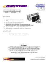
Vetus-Maxwell APAC Ltd 300 500 VC Windlass 15
Apply
grease here
Apply
grease here
Apply
grease here
Apply
grease here
Apply
grease here
Apply
grease here
Apply
grease here
Apply
grease here
Apply
grease here
Apply
grease here
Apply
grease here
Apply
grease here
Apply
grease here
Apply
grease here
Grease must be applied to motor face, gearbox locating lugs,
spacer tube, gearbox thread, shaft and clutch cone faces where shown.
Use CRC 3097 (or equivalent) spray to coat all under deck components to help guard against
corrosion. Failure to do so will void warranty.
Typical Greasing Instructions
Note: Picture shows typical winches, greasing instructions apply to all types using this motor gearbox and
spacertube arrangement.

300 500 VC Vetus-Maxwell APAC Ltd
16

____________________________________________________________________
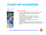
Vetus-Maxwell APAC Ltd 300 500 VC Windlass 17

300 500 VC Vetus-Maxwell APAC Ltd
18
/