Page is loading ...

Belt Drive Operator
Assembly and Installation
MM9000 Series
Need help? DO NOT RETURN to the store. Call: 800-543-1236
or visit www.mightymule.com
• Please read this manual and enclosed safety materials
carefully before installation.
Copyright
©
2018 Nortek Security and Control, LLC 10015816A X4
Mighty Mule Sales: 800-543-4283 • Fax 850-575-8912
Mighty Mule Technical Service 800-543-1236
For more information on Mighty Mule’s full line of Garage Door Openers, Gate Openers, Accessories and
Access Controls, visit www.mightymule.com
WARNING
To reduce the risk of injury to persons – Use this
opener only with sectional residential overhead doors.
Do not use on one piece or swing doors.
MM9545M – MM9434K – MM9333H

Table of Contents:
Important Installation Safety Instructions -------------- page i
Please Read Before Beginning Installation ------------ page ii
Opener Parts Included ---------------------------------- page 1
Recommended Tools ----------------------------------- page 1
Hardware and Parts Included -------------------------- page 2
Planning Overview -------------------------------------- page 3
Rail Assembly -------------------------------------------- page 4
Installing Belt -------------------------------------------- page 6
Mounting Header Bracket ------------------------------ page 8
Attaching Rail Header Bracket ------------------------- page 9
Mounting Opener to Ceiling ---------------------------- page 10
Attaching Door Bracket --------------------------------- page 12
Attaching Arm to Door Bracket ------------------------ page 13
Installing Photo Beams ---------------------------------- page 14
Smart Control WiFi Wall Station ------------------------ page 16
Installing Smart Control Wall Station ------------------- page 17
Installing Backup Battery ------------------------------- page 19
Connecting Power --------------------------------------- page 20
Testing the Wall Station --------------------------------- page 20
Aligning the Photo Beams ------------------------------ page 21
Programming Opener and Controls -------------------- page 22
Safety Reversal Test ------------------------------------- page 23
Programming Remotes --------------------------------- page 23
Installing and Programming Keypad ------------------- page 24
Adjusting the Force Factor ----------------------------- page 25
Using the Garage Door Opener ------------------------ page 26
Manual Disconnect -------------------------------------- page 26
Maintenance and adjustments ------------------------- page 27
Mighty Mule Smart Control APP ----------------------- page 28
Photo Beam Test ---------------------------------------- page 29
Replacing Remote Battery ------------------------------ page 30
Installing or Replacing Keypad Batteries -------------- page 30
Troubleshooting ----------------------------------------- page 31
FCC Notice and Warranty ------------------------------ page 32

IMPORTANT INSTALLATION SAFETY INSTRUCTIONS
Garage doors are large and heavy objects that move with the help of springs under high tension and electric
motors. Since moving objects, springs under tension, and electric motors can cause injuries, your safety and
the safety of others depends on you reading the information in this installation manual. If you have questions
or do not understand the information presented, call Mighty Mule Technical Support at 1-800-543-1236.
TO REDUCE THE RISK OF SEVERE INJURY OR DEATH TO PERSONS, REVIEW THESE INSTALLATION
SAFETY STEPS BEFORE PROCEEDING
1 READ AND FOLLOW ALL INSTALLATION INSTRUCTIONS.
2 Install only on a properly balanced sectional garage door. An improperly balanced door could result in
severe injury or death. Repairs to cables, spring assemblies, and other hardware must be made by a
quali ed service person before installing the opener.
3 Disable all locks and remove all ropes connected to the garage door before installing the opener. Ropes
connected to a garage door can cause entanglement and death.
4 If possible, install door opener 7 feet or more above the oor with the manual release handle mounted 6
feet above the oor.
5 Do not connect the opener to the power source until instructed to do so.
6 Locate the wall station within sight of the door at a minimum height of 5 feet so that small children
cannot reach it. Locate the wall station away from all moving parts of the door.
7 Install the User Safety Label on the wall adjacent to the wall station.
8 This operator system is equipped with an unattended operation feature. Only use this feature when
installed with sectional overhead doors. The door could move unexpectedly. NO ONE SHOULD CROSS
THE PATH OF THE MOVING DOOR.
9 Do not wear watches, rings or loose clothing while installing or servicing an opener. Jewelry or loose
clothing can be caught in the mechanism of the garage door or the opener.
10 DISCONNECT THE ELECTRIC POWER FROM THE GARAGE DOOR Opener BEFORE MAKING ANY
REPAIRS OR REMOVING THE COVER.
11 Disconnecting the Door from the Opener: With the door in any position (preferably closed), carefully pull
the red release handle. USE CAUTION IF THE DOOR IS OPEN. An open or partially open door may fall
rapidly if disconnected from the opener. Do not allow anyone in the path of the door.
Important Safety Information will follow
the words CAUTION and WARNING
which are used to emphasize
potentially hazardous situations.
IMPORTANT INSTALLATION SAFETY INSTRUCTIONS
i
WARNING
This type of warning note is used
to indicate possible mechanical
hazards that may cause serious
injuries or death.
WARNING
CAUTION
This type of warning note is
used to indicate the possibility
of damage to the garage door or
garage door opener.
WARNING
Children operating or playing with a garage door opener can injure themselves or others. The garage door
could cause serious injury or death. Do not allow children to operate the remote control(s) or the wall station.
Install the wall station out of reach of children and away from all moving parts of the door. The door must be
clearly visible from the wall station. A moving garage door could injure someone under it. Only activate the door
when it is properly adjusted, when it can be seen clearly, and when there are no obstructions to the door travel.

IMPORTANT: Check condition of your door and all its associated hardware.
Check tracks, springs, hinges, rollers. Is anything loose or
appear to be worn? If so, call a quali ed professional for an
evaluation and repairs. DO NOT ATTEMPT TO ADJUST
SPRINGS OR THEIR ATTACHED PARTS!
Check the door balance:
1. Slowly open the door all the way, and then close it all the
way. Notice if there is any binding, sticking or rubbing. The
door should move smoothly in both directions.
2. Raise the garage door about halfway up. Carefully release
the door and see if the door balances. It should stay in
place. Close the door.
IMPORTANT: If the garage door is unbalanced or the
door travel isn’t smooth, have a quali ed garage door
professional adjust or repair the door.
Please Read Before Beginning Installation
This garage door opener kit includes parts and supplies needed for installation in most garages and on
most sectional garage doors. A few additional parts and supplies may be needed for installation in your
garage and to your garage door. While going over these instructions, please note any additional items
you may need.
Measure the height of your door. For doors taller than 7’ and up to 8’ in height, you will need a rail
Extension Kit for the door to fully open.
Does the header above the garage door where torsion springs are used extend far enough above the
spring(s) to allow mounting of the header bracket? If not, or if you can’t tell you will probably need a
piece of 2”x 4” or 2”x 6” lumber to span across wall studs (see page 8).
If you have a nished ceiling, you will need a piece of angle iron which can span across beams or
trusses where the opener will be mounted (see page 11).
Remove all ropes and T-handles connected to the garage door. Remove or disable all locks connected
to the garage door. It is recommended that closed loop lifting handles with no protruding parts remain.
ii

1
OPENER PARTS INCLUDED
WARNING
!
Child can be pinned under automatic garage door.
Death or serious injury can result.
• Never let child walk or run under moving door.
• Never let child use door opener controls.
• Always keep moving door in sight.
• If person is pinned, push control button or use
emergency release.
• Test door opener monthly:
Refer to owner’s manual.
Place 1-1/2” object (or 2x4 laid at) on oor.
If door fails to reverse on contact, adjust opener.
If opener still fails to reverse door, repair or replace opener.
Do not remove or paint over this label.
Mount wall control out of child’s reach (at least 5 feet above oor)
Place next to wall control.
©2015
HANGING BRACKETS
(ANGLE IRON)
QTY–2
12 VOLT
BATTERY
(included with MM9545M)
OPENER POWER HEAD
DOOR ARM
2 PIECES
RAIL SECTIONS
QTY-4
DRIVE BELT
BELT TENSIONING TOOL
RAIL COUPLERS
QTY–3
WARNING
SIGN
3/8” Ratchet and 1/2", 3/8”
& 7/16" Sockets (thin-walled)
6-Foot Step Ladder
Wire
Labels (x6)
5/32” Bit for 1/4”
Lag bolt pilot holes
3/16” Bit for 5/16”
Lag bolt pilot holes
Drill
Pliers
Level
3 ft.-2x4”
Adjustable
Wrench
Pencil
Safety Goggles
Cutting
Disc
Hammer
Tape
Measure
Philips Head
Screwdriver
Tool Vice
Flat Head
Screwdriver
Wire
Stripper
Hack Saw
7/16”
wrench
1/2”
wrench
3/8”
wrench
Short Socket
Extension
Label
Label
RECOMMENDED TOOLS

2
PARTS PACK #1 – RAIL ASSEMBLY PARTS
1M
PARTS PACK #2 – OPENER INSTALLATION PARTS
PARTS PACK #3 – PHOTO BEAM PARTS
ACCESSORIES
1/4”-20 X 5/8”
CARRIAGE BOLT
QTY – 12
PULLEY
ASSEMBLY
QTY – 1
TROLLEY RELEASE
HANDLE QTY–1
36” RED RELEASE
HANDLE ROPE
WiFi WALL STATION
(included with MM9545M
and MM9434K)
KEYPAD
(included with
M9545M and
MM9333H)
3 BUTTON REMOTE
QTY-2
1/4”-20
LOCKNUT
QTY – 2
BEAM – BRACKET
QTY – 4
BEAM – RECEIVER
QTY – 1
BEAM – SENDER
QTY – 1
5/16”-18 LOCKNUT
QTY – 8
5/16”-18 X 1”
BOLT QTY – 8
5/16” X 1-1/2”
LAG SCREW
QTY – 4
5/16”-18 X 3/4”
BOLT QTY – 2
SPROCKET
QTY – 1
BELT
CLAMP
QTY – 1
SPROCKET
HOLDER QTY – 1
5/16”-18
LOCKNUT QTY – 2
TROLLEY
QTY – 1
GREASE TUBE QTY – 1
1/4”-20 X 1/2”
FLANGE BOLT
QTY – 1
1/4”-20 X 1/2”
FLANGE BOLT
QTY – 2
1/4” X 1-1/4”
LAG SCREW
QTY – 4
27 FEET 22 AWG
2-CONDUCTOR
WIRE (
for wall station)
WIRE SPLICE
CONNECTOR
QTY – 4
WIRE CLIP
QTY – 3
INSULATED
STAPLES
QTY – 20
HITCH PIN
QTY – 3
2-3/8”
CLEVIS PIN
QTY – 1
1-3/8”
CLEVIS PIN
QTY – 1
1-1/8”
CLEVIS PIN
QTY – 1
DOOR
BRACKET
QTY – 1
HEADER
BRACKET
QTY – 1
1/4”-20 X 3/4”
TAPERED FLANGE BOLT
QTY – 4
1/4”-20
LOCKNUT
QTY – 13
STANDARD WALL STATION
(included with MM9333H)
IF DOOR BECOMES OBSTRUCTED,
PULL DOWN ON HANDLE
NOTICE
1/4” x 3/4" Self-Tapping
Bolt Qty 2
1C
1E
1D
1G
1J
1L
1K
1H
1F
1B
1A
2A
2M
2L
3A
2B
2C
2D
2K
2G
3B
3D
3K
3C
3E
3H
3F
3G
3J
2F
2E
HARDWARE and PARTS INCLUDED

3
PLANNING OVERVIEW
FINISHED CEILING
Support bracket
and hadware.
See page 11-12.
Wall station
controller.
See page 17.
MM9000 Series
Garage Door Opener
Head Unit
Photo Beams
See page 15.
Access
Door
Header behind sheet
rock or exposed
See page 9.
Extension Spring
or
Torsion Spring
WARNING
!
Child can be pinned under automatic garage door.
Death or serious injur
y can result.
• Never let child walk or run under moving door.
• Never let child use door opener controls.
• Always keep moving door in sight.
• If person i
s pinned, p
ush
control button or use
emergency release.
•
Test door opener monthly:
R
e
f
e
r
to
o
wner’s m
a
nua
l.
P
la
ce 1-
1
/2
”
o
bject (
o
r 2
x4
l
a
i
d
a
t
)
o
n
oor.
If
door fail
s
to
r
ever
s
e o
n
c
on
t
a
c
t
,
adj
u
st
open
er
.
I
f o
pe
n
er
still
f
a
ils
t
o
re
v
ers
e
door
,
rep
air
o
r re
p
l
ace opener.
D
o
n
ot re
mo
ve
or
pa
int
ov
e
r
th
i
s
la
be
l.
M
o
unt wall contr
o
l
o
ut of
c
hi
ld
’s reach
(a
t
le
ast
5 feet a
b
ov
e o
o
r)
Pl
a
c
e n
ext t
o
w
a
ll co
n
trol
.
©
2
0
1
5
Safety Instruction label.
See page 20.
Horizontal or verticle
reinforcement may be
required for light weight
garage doors (berglass,
aluminum, steel, doors
with glass panels, etc.).
See page 13.
This is an example of a single 7 foot garage door installation. Depending on your application
additional materials may be required.
WARNING
To reduce the risk of injury to persons – Use this
opener only with sectional residential overhead doors.
Do not use on one piece or swing doors.
Additional Items You May Need
• Some 2”x4” lumber – use for header bracket support, installation spacer and force testing. See pages 8,10, and 23.
• Door reinforcement for door bracket attachment – required if you have a lightweight steel, aluminum, berglass or
glass panel door that does not have a mounting plate included.
• Additional angle iron or other materials for hanging the garage door opener head unit. See page 11.
• Belt rail extension kit (Model MMEXT8) is required if your garage door is 8 feet tall.

4
1/4”-20 x 5/8" Carriage Bolt
1/4”-20 Keps Nut
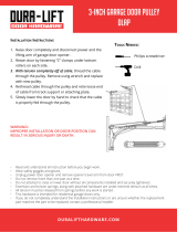
RAIL ASSEMBLY
Layout Rail Sections as show and connect using Rail Couplers and 1/4”-20 x 5/8” Carriage Bolts and 1/4”-20
Keps Nuts (supplied).
HARDWARE
1D
Section C
3 holes for mounting to head unit and stop bolt
2 holes for mounting Pulley
no holes
no holes
Section B
Section B
Section C
Section B
Section A
Section B
Rail Coupler
Rail Coupler
Rail Coupler
Section A
1
IF DOOR BECOMES OBSTRUCTED,
PULL DOWN ON HANDLE
NOTICE
HANGING BRACKETS
RAIL COUPLERS
DRIVE UNIT
TROLLEY
RELEASE
HANDLE
DOOR
ARMS
PULLEY
ASSEMBLY
TROLLEY
RAIL SECTIONS
BELT
SIDE VIEW
TOP VIEW
TROLLEY
PULLEY
ASSEMBLY
RAIL COUPLERS
ON THIS SIDE
OF THE RAIL
STOP BOLT
TRAVELER
(LATCHES INSIDE THE TROLLEY
AND IS USED TO ADJUST THE
BELT TENSION)
Assembly Overview
1D
1C
1C

5
5/16”-18 x 3/4" Bolt Grease Tube
5/16”-18 Keps Nut
1/4”-20 x 1/2" Flange Bolt
1/4”-20 Keps Nut
1D 1E 1G 1H
1M
SLIDE THE TROLLEY
ONTO RAIL SECTION “A”
PULLEY
HOLES
PUT NUTS ON BOLTS
WITH JUST A FEW TURNS,
DO NOT TIGHTEN NUTS
AT THIS TIME.
2 3
Slide the Trolley onto the rail Sections “A”. Be sure
of proper trolley orientation.
Attach the Pulley Assembly to rail Section “A” with
(2) 5/16”-18 x 3/4” bolts and (2) 5/16”-18 Keps nuts
(supplied). DO NOT FULLY TIGHTEN AT THIS TIME.
SECTION “C”
SPROCKET
FLAT SIDE UP
SPROCKET
HOLDER
APPLY
GREASE
APPLY GREASE
SECTION “C”
SECTION “C”
4
5
Install trolley stop using 1/4”-20 x 1/2” Flange
bolt and 1/4”-20 keps nut (supplied).
Apply grease to inside surfaces of sprocket holder
as shown and place the Sprocket into the sprocket
holder with at side up, then place Sprocket Holder
onto rail Section “C”, as shown.
HARDWARE
RAIL ASSEMBLY – continued
Completed rail assembly.
1G
1H
1E
1D
1M

6
INSTALL THE BELT
Lay belt on rail assembly with traveler placed through
trolley and traveler notch facing downward. Do not
place belt on pulley at this time.
Stretch the belt to the pulley end and rotate the
pulley assembly to slide the belt onto it.
Rotate the belt to bring the end of the traveler to 9”
from the end of the rail assembly.
Place belt on sprocket then snap belt clamp in
place.
Tighten the (2) 5/16”-18 x 3/4” bolts and (2) 5/16”-
18 Keps nuts to secure the pulley assembly to the
rail.
Rotate the sprocket (no more than a full turn in
either direction) until the at side of the sprocket
aligns with the at on the opener drive shaft.
LAY BELT ON RAIL WITH TRAVELER NOTCH FACING DOWN
NOTCH
BELT PASSES
THROUGH
TROLLEY
DO NOT PUT BELT
ON PULLEY YET
ROTATE THE PULLEY
TO PUT THE BELT ON
9”
PLACE BELT
ON SPROCKET
SNAP BELT CLAMP IN PLACE
PULL OUT
PULL THE SPACER
OUT OF THE TRAVELER
NOTE: KEEP THE
SPACER, IT CAN BE USED
FOR ADJUSTING THE BELT
TIGHTEN THE PULLEY NUTS AND BOLTS
ALIGN SPROCKET
AND SHAFT
1
3
5
2
4
6

7
Tighten
Loosen
Attach rail assembly to operator head using the four
1/4”-20 x 3/4” tapered ange bolts (supplied).
7 8
INSTALLING THE BELT – continued
Check that the tensioning spring in the traveler is
approximately 1” long. If it is not, hold the traveler
so the adjustment wheel is visible through the large
slot.
Use the belt tensioning tool, supplied with the drive
belt assembly, or a at blade screwdriver tighten
or loosen the tensioning nut until the spring is
approximately 1” long – the width of the
tensioning tool.
KEEP THE BELT TENSIONING TOOL FOR
FUTURE USE.
1/4”-20 X 3/4”
TAPERED FLANGE BOLT
HARDWARE
1D
1D
1D
1D
1D

8
IMPORTANT: On sheet rock walls you must
secure the header bracket to a solid wood
header behind the sheet rock.
MOUNTING HEADER BRACKET
Mount the header bracket on the center line
drawn above the door with the bottom edge of the
bracket on the line marked 2” above the high-rise
point. Mark and drill 3/16” pilot holes.
You may need to
add a header board
(2”x4” or 2”x6”)
Partial Header
Mark the centerline of the
door on the header and
the top panel of the door
Full Header
1 2
43
Close the door and from inside the garage, mark
the vertical centerline of the door on the header
wall and on the top panel of the door.
In some installations, the header bracket location
may be higher than the door header or no door
header exist. This will require adding a 2”x4” (or
larger) cross piece to the wall studs for mounting
the header bracket. Use lag screws (not supplied)
to attach the 2”x4” board to the studs.
Open the door to the high-rise point (the point
where the top edge of the door is highest above
the oor) and measure the distance to the oor.
Close the door and mark the header 2” above the
measured high-rise point.
High Point
To Floor
Mark Header
2" Above High Point
Door
Centerline of door
2 Inches
High-Rise point
of door
Mark and drill
3/16” pilot holes
To prevent SERIOUS INJURY or DEATH:
• Header bracket MUST be SECURELY fastened to a structural support on header wall or ceiling. DO
NOT install header bracket over sheet rock.
• Concrete anchors MUST be used if mounting header bracket or 2”x4” lumber into masonry.
• NEVER try to loosen, move or adjust garage door, springs, cables, pulleys, brackets or their hardware,
ALL of which are under EXTREME tension.
• CALL a quali ed door systems technician if garage door binds, sticks, or is out of balance. A door that
is not properly working may not reverse when required causing injury or death.
WARNING

9
5/16”x 1-1/2” Lag Screw Hitch Pin5/16” x 2-3/8” Clevis Pin
Secure the bracket to header board with two
5/16” x 1-1/2” lag screws (supplied).
5
1/2" Socket
Attach header
bracket with two
5/16” x 1-1/2”
lag screws
With door in the closed position, place assembled
opener on the carton packaging (to protect the
head from getting scratched) on the oor with rail
towards the door.
Insert the end of the rail into header bracket.
Insert the 5/16” x 2-3/8” clevis pin through
header bracket and rail pulley and secure with
the hitch pin.
1 2
HARDWARE
ATTACH RAIL TO HEADER BRACKET
2C
2C
2D
2D
2E
2E

10
MOUNTING OPENER TO CEILING
Raise the opener head and set it on top of a
stepladder. Center the opener head and rail with
the centerline mark on the top of the door.
Door
Place a 2x4 spacer
between the door and rail
Measure the distance from each of the opener’s
hanging tabs to the ceiling joists or angle iron
cross piece and cut angle iron to that length.
To avoid possible serious injury from falling garage
door opener, fasten it SECURELY to structural
ceiling supports.
Angle iron and lag screws are recommended. DO
NOT USE NAILS.
1
2 3
WARNING
Carefully open the door to the full up position. Lay a
2”x4” board at across the top section of the door
as a spacer. Rest the rail on the 2”x4” board.

11
Hang operator with two
5/16”-18 x 1” bolts and nuts
DOOR
RAIL
2”
Attach opener to hanging brackets using two
5/16”-18 x 1” hex bolts and two 5/16”-18 keps
nuts (supplied).
Open and close the door manually. The door
should clear the rail by at least 2”.
76
Joist under
sheet rock.
Diagonal supoport
for added stability.
Diagonal supoport
for added stability.
IMPORTANT: On a nished ceiling, be sure there
is a joist to fasten to under the sheet rock where
the cross piece will be located (use a stud nder).
If there is none, install a 2”x4” cross piece of wood
between the two closest joists to fasten the head
bracket hardware to.
For un nished ceilings: Hold each angle iron in
place, mark and drill 3/16” pilot holes, then attach
with two 5/16” x 1-1/2” lag screws (supplied).
For nished ceilings use an angle iron cross piece,
secured into ceiling joist with 5/16” x 1-1/2” lag
screws. Attach the two hanging brackets to the
cross piece with two 5/16”-18x1” hex bolts and
5/16”-18 nuts.
For additional stability add a diagonal support
piece of angle iron and secure with 5/16”-18x1”
hex bolts and 5/16”-18 nuts.
NOTE: Installation requirements vary with garage
construction. Hanging brackets should be angled
to provide rigid support. Not all hanging material is
provided.
4 5
5/16”x 1-1/2” Lag Screw 5/16”-18 x 1" Bolt 5/16”-18 Keps Nut
HARDWARE SUPPLIED
Angle Iron
1D
1D
1D
2F
2F
2F
2G
2G
2G

12
ATTACHING DOOR BRACKET
2” - 4”
CENTERLINE
HOLES
TO TOP
HORIZONTAL
SUPPORT
VERTICAL
SUPPORT
2” - 4”
Attach the trolley’s release lever to the red release
handle with the cord supplied so the handle is 6 feet
from the oor. Cut off any excess cord.
6 FEET FROM
THE FLOOR
Close the door. Align the top edge of the door
bracket 2” to 4” below the top edge of the door.
Align the vertical centerline drawn on the door with
the center of the bracket and mark holes.
If required, drill 3/16” pilot holes for mounting
bracket. Do not drill completely through the door.
Secure door bracket with two 1/4”x3/4” self-tapping
bolts (supplied). The self-tapping bolts are NOT
FOR USE ON WOOD DOORS!
1 2
3 4
Fiberglass, aluminum or lightweight steel
doors WILL REQUIRE reinforcement
before installation of door bracket. If your
door doesn’t have a reinforced mounting
support built in, contact door manufacturer
or garage door professional for instructions
on reinforcement or reinforcement kits for
using automatic door openers.
CAUTION
1/4” x 3/4" Self-Tapping Bolt
HARDWARE SUPPLIED
2M
2M

13
5/16”-18 x 1" Bolt 5/16”-18 Keps Nut
Hitch Pin
5/16” x 1-3/8” Clevis Pin 5/16” x 1-1/8” Clevis Pin
Align the two door arms so that
the holes in both arms overlap
and secure with 5/16” - 18 x 1”
bolts and nuts.
ATTACHING ARM TO DOOR BRACKET
Attach the curved door arm to the door bracket
using the 5/16” x 1-3/8” clevis pin and secure with
the hitch pin.
Insert the single hole end
of the straight door arm
into the slot in the trolley.
Secure with the 5/16”
x 1-1/8” clevis pin and
hitch pin.
Rotate the curved door arm upward to
meet the straight door arm connected
to the trolley. Align the two door arms
so that the holes in both arms overlap.
Secure with 5/16” - 18 x 1” bolts and
nuts provided.
1
3
2
HARDWARE SUPPLIED
2F
2F
2G
2G
2K
2K
2L
2L
2E
2E
2E

14
INSTALLING PHOTO BEAMS
Locate the photo beam brackets
so the beam centerline is 4”-6“ above the oor
Adjust the units so
lenses point toward
each other
Spring clip latches
into detent marks
to hole unit’s position
NOTE: The photo beams infrared light must not be obstructed by the door, or by any part of the door
hardware. Use wooden spacers between the beam brackets and wall if necessary to create proper clearance.
Assemble two photo beam brackets from the
four L-shaped brackets using one 1/4”-20 x 1/2”
bolt and 1/4”-20 keps nut per bracket (supplied).
Use the index marks on the brackets to make the
bracket assemblies equal lengths.
Position the assembled brackets on each side
of the door so the center line of the photo beam
lenses will be between 4”-6”” above the oor. Drill
5/32” pilot holes and mount the brackets with two
1/4” x 1-1/4” lag screws (supplied).
Insert the photo beams into the bracket holes
from inside the bracket with the lenses of the units
facing each other. Twist the units until the spring
clips lock into a detent mark on the brackets.
Adjust the photo beams so lenses point toward
each other. The spring clip latches into the detent
marks to hold unit’s position.
• Photo beams MUST be installed on the garage door to prevent serious injury or death.
• This required safety reversing sensor MUST NOT be disabled at any time.
• Install the photo beams no higher than 6” above the oor.
1 2
3 4
WARNING
HARDWARE SUPPLIED
1/4”-20 x 1/2" Bolt1/4” x 1-1/4" Lag Screw 1/4”-20 Keps Nut
Insulated Staples
3G
3G
3F
3F
3H
3H
3J

15
Photo beam wires
For non-prewired installations, route the wires from the photo beams using insulated staples supplied, up the
wall above the door hardware, over to the center of the door, then along the ceiling, and back to the opener
head. Cut the wires about 6” longer than needed to reach the opener terminals. Strip back ½” of insulation
from the ends of the wires.
WALLSTATION
COM
COM BEAM
UP
DOWN
LEARN
BEAM
COM
Beam wires
Twist one wire from each pair together, then
twist the other wire from each pair together.
Attach either twisted pair to the opener’s
BEAM terminal. Connect the other twisted
pair to the opener’s COM terminal.
Note: If an older system is being replaced,
use wire labels to mark connection types
prior to disconnecting wires.
IMPORTANT: Be careful to route the
photo beam wiring away from any
moving parts of the door or opener.
DO NOT route wires along the rail.
5
6
DO NOT
pierce wire
with staples
1/2”
3J

16
The Mighty Mule MM9545M and MM9434K come with the MMW200 WiFi wallstation and the MM9333H
comes with the MMW100 wallstation without WiFi capability. Installation is the same but functions are
different. Illustrations below will highlight the differences.
INSTALLING THE WALL STATION
Choose Placement of Wall Station
The Wall Station is typically mounted inside the garage on
the wall adjacent to the door into the house. It also can be
mounted in any other convenient place meeting the below
requirements.
NOTE: For Smart Control Wall Stations the composition of
your wall can adversely affect the strength of the Wi-Fi signal.
The best spot to mount the Smart Control Wall Station is on a
drywall-covered wall framed with wood studs and lled with
blown-in or batt insulation.
If possible, avoid af xing the Wall Station:
• to solid brick or concrete walls,
• to metal studs or walls with metal inside and
• on top of or near AC electrical lines.
Mount Smart Control Wall Station
at least 5 feet above oor level.
MMW200 MMW100
Vacation Lock
WiFi Link Button
Reset Button
WiFi Status LED
Vacation Lock
Light Control Buttons
( ) Turn light on/o
( – ) Dim the light
( + ) Brighten the light
NOTE: 22 AWG 2-conductor wall station and photo beam wire is supplied with the opener, Use this wire or the
installation’s pre-wiring.
UL NOTE: All low voltage Class 2 cable used with this opener must be UL Listed Type CL2, CL2P, CL2R, or CL2X
or other cable with equivalent or better electrical, mechanical, and ammability ratings.
/