Page is loading ...

Main PCB Assembly Kits
Part Numbers: 85205-3INT through 85205-8INT
Replacement Instructions
Introduction
This document provides the instructions to replace the Main PCB Assembly of an AirStar NEO International Dental Air System. These
instructions cover all AirStar NEO International models using the corresponding Main PCB Assembly Kit, part number 85205-3INT
through 85205-8INT, listed below. Please note that this task should only be done by an authorized dealer service technician.
Main PCB Assembly
Replacement Kits
AirStar Model Kit Part No.
AS12NEO-INT 85205-8INT
AS22NEO-INT 85205-3INT
AS30NEO-INT 85205-4INT
AS40NEO-INT 85205-5INT
AS50NEO-INT 85205-6INT
AS70NEO-INT 85205-7INT
PCB Removal:
1. Place the POWER circuit breaker to the O position.
2. Disconnect facility power going to the Electrical Box.
3. Remove and save the two (2) Front Screws securing the Electrical Box cover.
4. Open the Electrical Box by lifting from either side of cover.
5. Disconnect all Push-On Lugs that are connected to the PCB (Power, Motors,
Coolers, Sound Cover). Tag as necessary.
6. Disconnect display Ribbon Cable from the RIBBON TO DISPLAY connector.
AirStar NEO Main PCB Assembly
Important:
Make sure to remove all power to the AirStar NEO International before removing the main PCB assembly.
Voltage is present on circuit breaker terminals when facility power is connected.
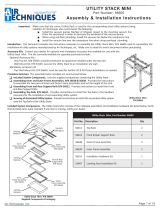
7. Disconnect the Transducer by carefully cutting the tubing with small clippers. Cut the tubing at the bottom of the loop under the
RIBBON TO DISPLAY connector.
8. Loosen the terminal screws of the Remote Switch (if used) and disconnect wires.
9. If necessary, disconnect the cables from the associated RJ45 connectors located on the left side of the Electrical Box.
10. Remove and save the six (6) Screws used to mount the PCB to Electrical Box housing.
11. Remove the PCB by carefully tilting the PCB right side up and sliding it out of the Electrical Box.
Transducer
Remote Switch
Ribbon Cable
Screw 1 Screw 2
Screw 3
Screw 4
Screw 6
Screw 5
RJ45
Connectors Ribbon to Display
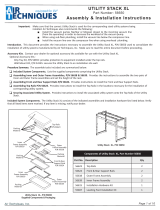
Push-On Lugs
Screw 1 Screw 2
Power
Switch
AirStar NEO International Electrical Box Cover
Typical AirStar
NEO International
(AS50NEO-INT Shown)
Dental Air System
International

PCB Installation:
1. Install the replacement PCB by tilting the left side down into the Electrical Box housing while aligning the RJ45 connectors with
the corresponding mounting holes on the left side of the Electrical Box. Carefully slide the board into the box.
2. Align the six screw holes of the PCB with the six screw holes of the Electrical Box housing. Using the same six (6) screws saved
during PCB removal, secure the PCB to the Electrical Box.
3. If necessary, connect the cables to the associated RJ45 connectors located on the left side of the Electrical Box.
4. If used, insert Remote Switch wires into the associated terminal locations (see diagram) and secure using terminal block screws.
5. Connect all Push-On Lugs to their respective locations (see diagram) on PCB (Power, Motors, Coolers, Sound Cover).
6. Connect display Ribbon Cable to PCB.
7. Join the tubing cut during PCB removal with the supplied tubing and coupler installed to the Transducer connector port of the
replacement PCB by pushing the tubing fully into the coupler.
8. Close Electrical Box cover and secure using two (2) Front Screws.
9. Connect facility power to Electrical Box.
10. Turn ON compressor by placing the POWER circuit breaker to the I position.
TUBING
TO TANK
© 2020 Air Techniques Inc., • P/N 85206INT, Rev. B • May 2021
1295 Walt Whitman Road | Melville, New York 11747- 3062
Phone: 800-247-8324 | Fax: 888-247-8481
Website: www.airtechniques.com
/