CMP In Ground Gunite Skimmer Operating instructions
- Category
- Above ground pool accessories
- Type
- Operating instructions

90500-025-120 RevC
C-M-P.COM
®
IN GROUND POOL SKIMMER INSTRUCTIONS
INSTALLATION INSTRUCTIONS & PRODUCT MANUAL
25100-XXX-XXX
25120-XXX-XXX
25140-XXX-XXX

2
Follow all applicable local and national regulations (e.g. NEC, CEC
whichever is applicable) during installation of the skimmer.
Plug equalizer line with plug using NSF listed PVC cement.
Do not stick hand into the skimmer pipe below the basket while the pump is running.
Risk of hair or body entrapment, drowning or disembowelment. Equalizer ttings can trap hair or body
parts causing severe injury or death.
Follow all necessary precautions when connecting a vacuum pump and cleaning the skimmer. Avoid
using a cracked or damaged skimmer. Do not step on cracked skimmer plate. Max weight 300 lbs.
Provide more than one suction source in pool system at all times.
If rusting is visible on Water Bond Kit (when installed), replace kit immediately.
A. SAFETY INSTRUCTIONS & PRECAUTIONS
CAUTION
DANGER
DANGER
DANGER
WARNING
WARNING
WARNING
IMPORTANT SAFETY INSTRUCTIONS.
READ AND FOLLOW ALL INSTRUCTIONS
• Use one skimmer per 500 square feet of pool surface area. Suction line sizes are based on a water velocity of less than
seven feet per second. Since building codes vary, check your local building code before installing pool and skimmer.
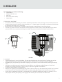
• NOTICE: When the skimmer is formed into the concrete shell of the pool it should be surrounded by at least 4” of
structural concrete in a monolithic pour, using a cold joint as shown in installation drawings (Fig. 1).
• For optimum skimmer functionality, the skimmer should be placed relative to the prevailing wind and water ow direction.
SAVE THESE INSTRUCTIONS

3
B. INSTALLATION
Your CMP Skimmer includes the following:
• Skimmer Body
• Skimmer Collar & Cover
• Weir Door
• Float Valve (select models)
• Debris Basket
1. DECK & POOL PLACEMENT
• For optimum skimmer functionality, the skimmer should be placed relative to the prevailing wind and water ow direction.
• Support skimmer securely in position during installation. An “x” shaped support is provided on the bottom of the skimmer
for temporary mounting on a 2in stand pipe.
• Rebar tie points to tie the skimmer to the rebar cage of the pool are provided at the top of the skimmer.
• The deck ring collar has a friction t that allows vertical adjustment. Extension collars (25526-200-000) may be stacked
upon each other to accommodate deck height as needed. See product dimensions for detailed measurements.
Collar
Rebar
Ties
Water
Stop
Cold
Joint
Concrete
Concrete
Water
Level
To Pump
Suction
To Main Drain
or Equalizer
Optionally
Plug Second
Port
FIGURE 1
2. PLUMBING
• The skimmer has two 2” ports for plumbing. The rear port should connect to the pool suction. The front port may be
used as an equalizer line or connect to the pool main drain. If the front port is not used it should be plugged.
• Assemble piping and pipe ttings to skimmer. All piping must conform to current local and state plumbing and sanitary
codes.
• Long pipe runs and elbows restrict water ow. For best eciency, use the fewest possible ttings and 2” pipe for 2”
skimmers. Using sweep 90 ̊ ttings or two 45 ̊ ttings in place of a single 90 is more ecient.
• For pressure testing seal o any unused ports.
• NOTICE: Over tightening the threaded plugs may result in failure of the plug or the skimmer body and will not be covered
under the terms of the Limited Warranty. DO NOT use tapered metal plugs as this will void manufacturer’s warranty.
• Ensure piping is adequately supported on undisturbed earth. If additional backlling and tamping is necessary, do not
stress pipe or skimmer port by lifting or moving pipe after skimmer port connections have been made.
IMPORTANT SAFETY INSTRUCTIONS.
READ AND FOLLOW ALL INSTRUCTIONS

4
B. INSTALLATION
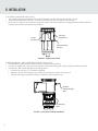
3. OPTIONAL OVERFLOW PORTS (FIG 2)
• Two overow ports are provided on the rear of the skimmer, one for 3/4in pipe and one for 1 in pipe
• The ports are sealed from the factory. To utilize an overow port, drill out using a 3/4in hole saw.
• Glue 3/4in or 1in pipe to the correct port using PVC cement and drain overow to an appropriate area following all local
building code and/or environmental requirements.
Optional Bonding
Wire Port
3/4in Pipe
Overflow Port
1in Pipe
Overflow Port
FIGURE 2: OVERFLOW PORTS
4. WATER BONDING - POOL DEFENDER® MODELS ONLY (FIG 3)
• Pool Defender models include a bonding wire for integrated water bonding.
• Connect the copper wire in the rear of the skimmer to the pool bonding grid or loop using the provided connector.
• As required in NEC section 680.26(C) the bonding device:
• Consists of at least 9 sq. in. of conductive material
• Shall be in contact with the water 24/7, whether the circulation system is running or not
• The connector (lug) must NOT be unable to “back o” (due to vibration, etc.)
Optional
Copper Bonding
Wire
9in2 Bonding
Plate
FIGURE 3: OPTIONAL WATER BONDING

5
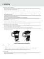
C. OPERATION
1. OPERATION FOR ALL SKIMMERS
• Water is pulled through the skimmer by the suction of the pump. Water ow carries oating debris into the skimmer
where it is collected in the skimmer basket.
• The oating weir creates a better water ow and increases eciency.
• The water level of the pool should be kept at least 2” above the bottom of the mouth of the skimmer to ensure proper
operation.
• To adjust the skimmer ow rotate the diverter plate on the oat valve or in the skimmer until the desired ow is achieved.
• If multiple skimmers are installed, rotate the diverter plate in each skimmer over the pump port to restrict and balance
the ow from each skimmer.
• To vacuum the pool, remove the oat valve and close the diverter plate over the main drain. Install the skimmer vacuum
in the skimmer and connect to vacuum hose.
• Empty the skimmer basket as needed to maintain ow through the skimmer.
• To enhance skimming on low ow pump settings, set drain & skimmer three-way valve to divert suction to skimmer (if a
valve is present).
2. OPERATION WITH DIVERTER PLATE
• For full ow, rotate diverter plate completely open.
• To adjust ow, rotate over the pump port until desired ow is achieved.
• To vacuum, either remove cover and basket OR insert the skimmer vacuum into skimmer on top of the basket. Screw the
hose adapter into the pump port. Fill hose with water and insert over the hose adapter.
3. OPERATION WITH FLOAT VALVE (OPTIONAL)
• If the water level drops below the mouth of the skimmer or if the basket is clogged and no water can ow through it, the
oat valve will automatically close over the ow ports.
• This diverts all water ow to the pump from the main drain line and prevents possible air lock.
• When the pump is shut o or water level returns to normal, the oat valve will oat back to the top of the cavity, allowing
normal operation to resume.
A
A
SECTION A-A
SCALE 1 : 8
BOTTOM VIEW
D
C
B
A
A
B
C
D
1
2
3
4
5
6
7
8
8
7
6
5
4
3
2
1
Custom
Molded
Products
Vic Walker
CAD GENERATED DRAWING,
DO NOT MANUALLY UPDATE
SIZE
Doc. Number
Part Number
B
SHEET
2
OF
6
REV.
APPROVALS
DRAWN
RESP ENG
UNLESS OTHERWISE SPECIFIED
DIMENSIONS ARE IN INCHES
TOLERANCES ARE:
1/X
1/8
A
XXXX
Part Name
Vic Walker
XXXX
IR #
.X
.030
.XX
.010
.XXX
.005
.XXXX
.002
Degrees
.5
5-17-21
Scale:
Rev. Date
5-17-21
XXXX
NONE
-
-
-
THE INFORMATION CONTAINED IN THIS DRAWING IS THE SOLE PROPERTY OF
CUSTOM MOLDED PRODUCTS. ANY REPRODUCTION IN PART OR WHOLE WITHOUT
THE WRITTEN PERMISSION OF CUSTOM MOLDED PRODUCTS IS PROHIBITED.
DATE
_
_
_
Float
Valve Debris
Basket
Weir
A
A
SECTION A-A
SCALE 1 : 8
BOTTOM VIEW
D
C
B
A
A
B
C
D
1
2
3
4
5
6
7
8
8
7
6
5
4
3
2
1
Custom
Molded
Products
Vic Walker
CAD GENERATED DRAWING,
DO NOT MANUALLY UPDATE
SIZE
Doc. Number
Part Number
B
SHEET
2
OF
6
REV.
APPROVALS
DRAWN
RESP ENG
UNLESS OTHERWISE SPECIFIED
DIMENSIONS ARE IN INCHES
TOLERANCES ARE:
1/X
1/8
A
XXXX
Part Name
Vic Walker
XXXX
IR #
.X
.030
.XX
.010
.XXX
.005
.XXXX
.002
Degrees
.5
5-17-21
Scale:
Rev. Date
5-17-21
XXXX
NONE
-
-
-
THE INFORMATION CONTAINED IN THIS DRAWING IS THE SOLE PROPERTY OF
CUSTOM MOLDED PRODUCTS. ANY REPRODUCTION IN PART OR WHOLE WITHOUT
THE WRITTEN PERMISSION OF CUSTOM MOLDED PRODUCTS IS PROHIBITED.
DATE
_
_
_
Diverter
Plate
FIGURE 4: SKIMMER OPERATION COMPONENTS
4. SWEEP/BRUSH POOL
• Divert all suction to the main drain by:
• OPTION 1: Use valve to divert all water to the suction away form the skimmer.
• OPTION 2: Hold the weir above normal operating level and allows the oat to snap shut. To reset the oat valve
assembly, turn o the pump for 10-15 seconds. The oat valve will rise to the top of the skimmer cavity.
• OPTION 3: Remove the oat valve assembly, close the diverter plate, and replace.
5. VACUUM POOL
• OPTION 1: Remove cover, basket and oat valve assembly. Screw the hose adapter into the pump port, ll the hose with
water, and insert over adapter.
• OPTION 2: Insert the skimmer vacuum into skimmer on top of the basket.

6
WINTERIZING
• Requirements for winter will vary depending on region - follow normal winter and freeze protection practices for your
area.
• For areas that require partial drainage and/or clearing lines to prevent freeze damage:
• Drain the pool water below the skimmer mouth.
• Use a blower to clear the plumbings lines of water and cap or close the line with a valve to prevent freeze damage.
• Optionally ll plumbing lines with foam rope/backer rod to protect from freeze damage.
• Use a CMP Winterizing tube to prevent freeze damage from accumulated water.
WEIR: Periodically check weir for free operation. Replace if damaged or worn.
STRAINER BASKET: Check strainer basket every few days for accumulated leaves, debris, etc. Empty basket as required. Reset
oat valve if it closed.
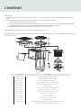
D. MAINTENANCE
CMP P/N DESCRIPTION
1a 25544-000-000 WHITE SKIMMER LID/COVER, ROUND
1b 25538-500-000 WHITE SKIMMER LID/COVER, SQUARE
2b 25547-000-000 WHITE SKIMMER COLLAR, ROUND
1a-2a 25544-900-000 WHITE SKIMMER COVER & COLLAR, ROUND
1b-2b 25538-900-000 WHITE SKIMMER COVER & COLLAR, SQUARE
3 25140-000-900 DEBRIS BASKET
3 25140-000-900 BASKET FOR WATER BOND SKIMMER (WHITE)
4 25140-000-700 FLOAT VALVE ASSY (FOR ALL STYLES)
5 25140-000-040 FLOAT VALVE GASKET (FOR ALL STYLES)
625140-000-003N STOVE RING FOR FLOAT VALVE
–– 25140-000-004N STOVE RING GASKET
725140-000-060 DIVERTER PLATE (FOR ALL STYLES)
825140-000-800 WEIR DOOR, WHITE
9 25140-500-110 REPLACEMENT WATER BOND PLATE (COPPER WIRE NOT INCLUDED)
–– –– FOR MORE COLOR OPTIONS SEE WWW.C-M-P. C O M
8
7
9
6
1a1b
3
4
5
2a2b

7
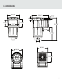
E. DIMENSIONS
7-3/8" 5-1/4"
8-1/2"
11-5/16"
20-1/4"
11-3/8"
15/16"
5-3/4"
1-1/2"
15-3/8"
3-9/16
10-1/4"
10 7/16"
10 7/16"

CMP, LLC
36 HERRING ROAD, NEWNAN, GA 30265
WWW.C-M-P.COM
0521sb
Record Information on this System Below & Keep for Your Records
Installer _______________________________________________________________
Purchased From _______________________________________________________
Installation Date _____________________________
Model Number ______________________________
Pool Size in Gallons __________________________
CMP Customer Service & Tech Support
Toll Free: 1-800-733-9060
FAX: 770-732-7115
suppor[email protected]
Warranty Questions
Support Resource & Videos Online
c-m-p.com/resourcecenter
-
 1
1
-
 2
2
-
 3
3
-
 4
4
-
 5
5
-
 6
6
-
 7
7
-
 8
8


CMP In Ground Gunite Skimmer Operating instructions
- Category
- Above ground pool accessories
- Type
- Operating instructions
Ask a question and I''ll find the answer in the document
Finding information in a document is now easier with AI
Related papers
-
CMP FlowSkim™ Basket Handle Operating instructions
-
-
-
-
-
-
-
-
-
Other documents
-
 WaterWay Renegade User manual
-
AquaStar SKR1xx User manual
-
AquaStar SKR15NL103 User manual
-
 AquaStar FLOW STAR SKRFL12 Series Installation and User Manual
-
 Paramount Fitness Paraskim V Owner's Manual And Installation Manual
-
WaterWay Renegade Gunite Skimmer User guide
-
 Vogue Industrial ABOVE GROUND SWIMMING POOL User manual
-
 baracuda alpha 3 Owner's manual
-
Hayward SP1091LX Owner's manual
-
Zodiac G2 User manual


