Ei Electronics EiA650RFZ User manual
- Category
- Smoke detectors
- Type
- User manual
This manual is also suitable for

EiA600 Series
Z-Wave Smoke Alarm
Quick Start
This device combines a Z-Wave compatible Smoke Alarm specifically designed to comply with North American standards and a Z-Wave Communication
Module. Pressing the Inclusion Button (located on the Z-Wave Communication Module) for one second adds (includes) or removes (excludes) the
device to/from the Z-Wave network.
Please refer to the chapters below for detailed information about all aspects of the product.
Model & Description:
Alarm Model Description
EiA660RFZ Z-Wave Smoke/Heat Alarm
EiA650RFZ Z-Wave Smoke Alarm
Product description
This product combines a certified stand-alone Smoke or Combination Smoke/Heat Alarm with a plug-in Z-Wave module to form a wirelessly reporting
Smoke or Smoke/Heat Alarm. This enables the unit to be wirelessly Linked to a third party Z-Wave Controller. When any of the Linked products are
triggered by smoke or heat the unit will transmit messages to the main controller. As a FLiRS enabled device each Alarm will trigger all other Alarms
provided they share the same association. The Smoke Alarm is certified by Underwriters Laboratories and satisfies all UL217 contemporary legal
requirements and the Z-Wave module is certified by the Z-Wave Alliance.
This premium quality Smoke Alarm is monitored electronically and will report the following:
1. Alarm on sensing smoke (EiA650RFZ) / alarm on sensing smoke / heat (EiA660RFZ)
2. Battery status reporting
3. Sensor Fault
4. Alarm removal from mounting plate
The device is a secure Z-Wave Plus device and can be used in a wireless Z-Wave network. It supports secure communication only when the central
controller also supports secure communication. Even if included securely the device is able to communicate unsecured with devices included unsecure
using the association groups 2 and 3.
Quick Installation Guidelines
Please refer to the installation guide of the EiA600 Series Alarms for information about how and where the Smoke Alarm should be installed. Alarms
should be installed as per NFPA72.
• The first step is to fix the mounting base in the desired location as per the installation guide for the Smoke Alarm.
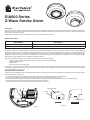
• Next remove the battery isolation strip from the battery compartment to power the Alarm (see Figure 1).
• Include the Smoke Alarm into your existing Z-Wave based Smart Home Network by pressing the Inclusion button once (see Figure 2).
• The Green LED on the Z-Wave module will flash during the inclusion process.
• Once included place the Smoke Alarm on the mounting base and turn clockwise.
Figure 1
Inclusion Button
A
ntenna
LED Connector Pins
Top Side Bottom Side
Figure 2
1

Module Removal & Installation
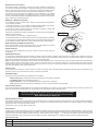
The Z-Wave module is pre-fitted. To remove the module, carefully use the pull tag
to remove the module from the Alarm. To refit the module plug it into the base of the
Alarm while being careful to align the connector pins and insert the flexible antenna
into the antenna hole (See Fig 3). N.B. Ensure that the module is fully inserted.
The Z-Wave RF module will be pre-installed by the manufacturer. If the Z-Wave
module is removed and fitted to another host Alarm, the label displaying the
FCC ID: A5FEiA600ZW & ISED ID: 22380EiA600ZW must be placed on the new host
Alarm, visible when installed (see Fig 4).
Adding to a Network (Inclusion)
Do not attempt to add your Z-Wave Alarm unless you are familiar with the operation
of your Z-Wave Controller.
1. Read the instruction for your Z-Wave controller regarding adding new devices.
Then initiate the inclusion function within your Z-Wave controller.
2. Pressing the button ‘Inclusion Button’ for one second includes the device with
Security. (see Fig 2) The Green LED will flash.
If the button is pressed for at least 2.5 seconds the inclusion will be done without the
(Security Command Class).
3. If the inclusion is not successful , restart from step 1.
4. Press the test button on the Alarm and check that the controller receives a notification.
5. Once the Alarm is included in the Z-Wave system you can define association groups
via the Z-Wave controller. Please refer to your Controller manual for further details.
Removing from the Network (exclusion)
Single click the Button to start the removal process. The LED will blink a couple of
times. *Note a device must be already added to the network.
Check-In Period:
As this is a FLiRS enabled device the check-in period is once a second and is not
configurable.
Operating the device
In case smoke is detected by the Smoke Alarm the device will sound and the wireless module will issue a Z-Wave alarm command to the main
controller and other associated devices. The wireless module will also report a low battery warning, Sensor or Chamber Fault as they occur. A tamper
alarm will be reported when the Alarm is removed from the mounting plate.
Note: All communication of the wireless module is performed with application level security if the device was included securely and all communication
partners support secure communication as well. In case a non-secure device is associated for switching on a Smoke Alarm, the Smoke Alarm will
detect this and change its communication style with this very device to non-secure. This process happens one time and will take about 20 seconds.
This delay will happen on first communication only.
Factory reset
To do a factory reset press the inclusion button for at least 10 seconds. After 5 Seconds the LED will start to blink and stop 5 seconds later. This
procedure should only be used when the primary controller is inoperable.
Alarm Messages
The device will issue the following (unsolicited) alarm messages:
- Smoke Detected (this message will also be issued when the Test button is pressed)
- Low Battery Alarm (when the battery goes low)
- Tamper Detected (on, when the Smoke Alarm head is removed from the base)
- Fault (when the smoke or heat sensor is deemed to be faulty or smoke chamber is contaminated)
Interconnect Function
The Z-Wave modules has FLiRS enabled on it, this allows for each Alarm in the system to communicate to the other Alarms in the event of a fire, thus
when one device senses smoke/heat it can communicate to the other Alarms to also sound their sirens.
Node Information Frame
The Node Information Frame is the business card of a Z-Wave device. It contains information about the device type and the technical capabilities.
The inclusion and exclusion of the device is confirmed by sending out a Node Information Frame. Beside this it may be needed for certain network
operations to send out a Node Information Frame.
A simple click on the ‘Inclusion Button’ sends a NIF.
Associations
Z-Wave devices control other Z-Wave devices. The relationship between one device controlling another device is called association. In order to control
a different device, the controlling device needs to maintain a list of devices that will receive controlling commands. These lists are called association
groups and they are always related to certain events (e.g. button pressed, sensor triggers, ...). In case the event happens all devices stored in the
respective association group will receive a common wireless command. Please refer to your Z-Wave controller manual for further instructions.
Association Groups:
1Lifeline (max. nodes in group: 10)
2Alarm Reports (max. nodes in group: 10)
3Switching Command when Alarm (max. nodes in group: 10)
This device employs FLiRs, please ensure your controller is set to exclude
this device from polling. Failure to do this will result in excessive battery
drain and extremely low battery life
2
Figure 3
FCC ID: A5FEiA600ZW
ISED ID: 22380EiA600ZW
FCC ID: A5FEi200ZW
ISED ID: 22380EiA200ZW
Figure 4

Configuration Parameters
Z-Wave products are supposed to work out of the box after inclusion. As this is a life safety device we strongly recommend that you don’t change the
configuration parameters as this may effect the performance of the product.
Limitations of the Z-Wave System
1. The Z-Wave protocol is not a life safety protocol and should not be relied upon for life safety.
2. If your internet connection is lost, communication from your 3rd party controller (i.e. to cloud or mobile devices) may not be
possible. Your Alarm will still continue to operate as a stand alone Alarm and does not rely on an internet connection to do so.
Command Classes
Supported Command Classes
• Basic (version 1)
• Binary Switch (version 1)
• Binary Sensor (version 2)
• Association Group Information (version 1)
• Device Reset Locally (version 1)
• Z-Wave Plus Information (version 2)
• Configuration (version 1)
• Alarm (version 5)
• Manufacturer Specific (version 2)
• Powerlevel (version 1)
• Battery (version 1)
• Association (version 2)
• Version (version 2)
• Wake-up (version 2)
Controlled Command Classes
• Basic (version 1)
Z-Wave Technical Data
Battery Type Powered from Alarm Battery
Frequency @ 908.42 MHz (SRD Frequency Band according FCC Part 15)
Wireless Range up to 100m outdoor, 40m in buildings
Explorer Frame Support Yes
SDK 6.51.6
Device Network Role Reachable Sleeping Slave (RSS)
Device Type Sensor
Routing No
FLiRs Yes
FCC
This device complies with Part 15 of the FCC Rules. Operation is subject to the following two conditions:
(1) this device may not cause harmful interference, and
(2) this device must accept any interference received, including interference that may cause undesired operation.
ISED
This device complies with ISED’s license-exempt RSSs. Operation is subject to the following two conditions:
(1) This device may not cause interference; and
(2) This device must accept any interference, including interference that may cause undesired operation of the device.
P/N B18579 Rev3© Ei Electronics 2017
Please return to:
Customer Service
Ei Electronics US, Inc
2 Tunxis Road, Suite 209
Tariffville, Connecticut 0608
web: www.ei-electronics.com
3
-
 1
1
-
 2
2
-
 3
3


Ei Electronics EiA650RFZ User manual
- Category
- Smoke detectors
- Type
- User manual
- This manual is also suitable for
Ask a question and I''ll find the answer in the document
Finding information in a document is now easier with AI
Other documents
-
Popp Smoke Detector User manual
-
Popp Ei600ZW User manual
-
-
Silicon Labs S14278 User guide
-
-
-
-
Aeotec Door / Window Sensor 7 Pro User guide
-
-