Page is loading ...

Instruction
Z-Wave Plus V2 Application Framework SDK7
Document No.:
INS14259
Version:
11
Description:
-
Written By:
JROSEVALL;JFR;PSH;KEWAHID;JSMILJANIC;COLSEN;NOBRIOT; ALMUNKHA
Date:
Reviewed By:
NTJ;ABRUGGER;BBR;CRASMUSSEN;LTHOMSEN;COLSEN;SCBROWNI;CAOWENS
Restrictions:
Public
Approved by:
This document is the property of Silicon Labs. The data contained herein, in whole or in
part, may not be duplicated, used or disclosed outside the recipient for any purpose. This
restriction does not limit the recipient's right to use information contained in the data if it
is obtained from another source without restriction.

INS14259-11 Z-Wave Plus V2 Application Framework SDK7 2020-06-17
silabs.com | Building a more connected world.
Page ii of v
REVISION RECORD
Doc.
Rev
Date
Author
Pages
Affected
Brief Description of Changes
1
20181120
COLSEN
JFR
ALL
Based on INS13953– Z-Wave Plus Application Framework v6.8x.0x
Initial revision.
1
20181213
KEWAHID
5.4
Added a True Status description in the Architecture section.
1
20181213
ESOSTERG
8
Updated Utilities section.
1
20181214
JESMILJA
7
Updated Command Classes description
2
20181217
JFR
5.1
8.4
9
Added application memory constraints
Updated peripheral drivers
Added firmware update images and bootloader
3
20190116
MLEDESMA
ALL
Grammar and structure (consistent format) modification
4
20190313
JOROSEVA
5.3
Updated description of Power Management
4
20190315
JOROSEVA
6.3
Added description of NVM3 File System
4
20190315
JESMILJA
5.1
6.2
Updated description of how to create application
Updated instruction of usage of config file
Removed 5.2.6 and 5.2.7 as obsolete
4
20190320
JOROSEVA
6.6
Updated description of ApplicationInit() and ApplicationTask()
4
20190320
JFR
9.2
8.4.3
6.3
All
Updated flashing of boot loader and app.
Added ADC driver.
Added how to adjust Tx power.
Minor typos.
5
20190325
JFR
6.5
Added watchdog.
6
20190704
CHOLSEN
6.4
Minor text changes and fix of example code.
7
20190712
SCBROWNI
All
Minor typos
8
20190812
PESHORTY
5.2
Added description of ZAF_SetMaxInclusionRequestIntervals
8
20190829
PESHORTY
6.5
Added note about watchdog always being enabled in production code
8
20190829
CHOLSEN
8.6
Added section “Callback before entering sleep”
8
20190903
JFR
8.4.1.1
GPIO port usage in serial API application.
8
20190903
JOROSEVA
5.2.1
Learn mode status events.
8
20190903
SCBROWNI
5.2
Editorial review of Section 5.2
9
20191022
CHOLSEN
JFR
8.4.2
4
Minor correction in source code.
Added “Introduction to the Z-Wave Technology”.
10
20200518
JFR
9
Added location of OTA key.
11
20200611
SCBROWNI
All
Tech Pubs review of new sections since version 7

INS14259-11 Z-Wave Plus V2 Application Framework SDK7 2020-06-17
silabs.com | Building a more connected world.
Page iii of v
Table of Contents
1 DEFINITIONS, ACRONYMS AND ABBREVIATIONS...........................................................................1
2 INTRODUCTION ............................................................................................................................2
3 PURPOSE ......................................................................................................................................2
4 INTRODUCTION TO THE Z-WAVE TECHNOLOGY.............................................................................3
4.1 Protocol Stack Overview ....................................................................................................................3
4.2 Classic Z-Wave ...................................................................................................................................4
4.3 Node Types ........................................................................................................................................4
4.4 Controllers .........................................................................................................................................4
4.5 Slaves .................................................................................................................................................4
4.6 Network Operation ............................................................................................................................5
4.7 Routing Principles ..............................................................................................................................5
4.8 Application Development ..................................................................................................................5
4.9 Managing Interoperability .................................................................................................................6
5 ARCHITECTURE .............................................................................................................................7
5.1 Application Memory Constraints .......................................................................................................8
5.2 Smart Start .........................................................................................................................................9
5.2.1 Starting smart start inclusion ..................................................................................................9
5.2.2 Configuring smart start inclusion ............................................................................................9
5.3 Power Management ........................................................................................................................11
5.4 True Status Module..........................................................................................................................11
5.4.1 True Status Engine (TSE)........................................................................................................11
5.4.2 True Status Callback Functions..............................................................................................12
5.4.3 True Status Sequence Flows..................................................................................................13
5.4.3.1 Use Case 1 – State Change Triggered by a Command from a Remote Note ....................14
5.4.3.2 Use Case 2 – State Change Triggered by a Local Change .................................................15
6 HOW TO DEVELOP A Z-WAVE PLUS APPLICATION .......................................................................16
6.1 Create Application Folder and Set Up Build Environment ...............................................................16
6.1.1 Select the application to start with .......................................................................................16
6.1.2 Create new Simplicity Studio project ....................................................................................16
6.2 Setting Up config_app.h...................................................................................................................16
6.2.1 Generic Type, Specific Type, and Device Options .................................................................16
6.2.2 Role Type, Node Type, Icon Type, and User Icon Type (Z-Wave Plus Info CC) ......................17
6.2.3 Manufacturer Specific CC / Firmware Update ......................................................................17
6.2.4 Association Group Information (AGI)....................................................................................17
6.2.5 Security..................................................................................................................................19
6.3 Setting Up config_rf.h ......................................................................................................................19
6.4 Setting Up Files in Non-Volatile Memory.........................................................................................20
6.5 Watchdog Enable/Disable................................................................................................................21
6.6 Source File........................................................................................................................................21
6.6.1 Command Class Lists Configuration ......................................................................................22

INS14259-11 Z-Wave Plus V2 Application Framework SDK7 2020-06-17
silabs.com | Building a more connected world.
Page iv of v
6.6.2 Endpoint Configuration .........................................................................................................22
7 COMMAND CLASSES ...................................................................................................................24
7.1 General Interfacing to CCs ...............................................................................................................24
7.1.1 Unsolicited Transmission ......................................................................................................24
7.1.2 Respond to Received Command ...........................................................................................25
7.1.3 CC Version .............................................................................................................................25
7.1.4 True Status Support ..............................................................................................................26
7.2 Implementing a CC...........................................................................................................................26
7.3 Association Group Information CC...................................................................................................26
7.3.1 API .........................................................................................................................................26
7.4 Battery CC ........................................................................................................................................26
7.5 Indicator CC......................................................................................................................................27
7.6 Notification CC Version 8 .................................................................................................................27
7.7 Supervision CC .................................................................................................................................27
7.7.1 Configuration Scenarios ........................................................................................................28
7.7.1.1 Default Configuration .......................................................................................................28
7.7.1.2 Handle More Supervision Reports....................................................................................28
7.7.1.3 Control Supervision Reports.............................................................................................30
8 UTILITIES.....................................................................................................................................32
8.1 AGI Module ......................................................................................................................................32
8.1.1 Configuration of AGI..............................................................................................................32
8.1.1.1 Example 1: How to Set Up AGI for a Wall Controller........................................................33
8.1.1.2 Example 2: How to Extend the Wall Controller with 2 Buttons .......................................34
8.1.2 Using AGI...............................................................................................................................35
8.2 Association Module .........................................................................................................................35
8.2.1 Initialization...........................................................................................................................36
8.2.1.1 Example 3: How to Use Group Mapping ..........................................................................37
8.3 Interfacing Firmware Update Module “ota_util”.............................................................................38
8.4 Peripheral Drivers ............................................................................................................................39
8.4.1 GPIO ......................................................................................................................................39
8.4.1.1 GPIO port usage in serial API............................................................................................40
8.4.2 UART Driver...........................................................................................................................41
8.4.3 ADC Driver.............................................................................................................................42
8.5 Event Distributor..............................................................................................................................43
8.5.1 Event Loop.............................................................................................................................43
8.5.2 Event Queues ........................................................................................................................44
8.5.3 Event Handler........................................................................................................................45
8.5.4 Job Event Queue ...................................................................................................................46
8.5.5 Simple Event Handling ..........................................................................................................46
8.5.6 Multiple Event Jobs Handling................................................................................................47
8.6 Power Manager................................................................................................................................48
8.7 Application Timers ...........................................................................................................................50

INS14259-11 Z-Wave Plus V2 Application Framework SDK7 2020-06-17
silabs.com | Building a more connected world.
Page v of v
9 FIRMWARE UPDATE IMAGES AND BOOTLOADER ........................................................................52
9.1 Generate GLB Files...........................................................................................................................52
9.2 Flashing the Boot Loader and App ...................................................................................................53
REFERENCES.......................................................................................................................................54
Table of Figures
Figure 1. The Z-Wave Plus Application Framework Architecture ................................................................7
Figure 2. AGI Behavior Diagram.................................................................................................................32
Figure 3. Wall Controller that sends Command Class Scene and Device Reset Locally over Association
group 1 (lifeline) and Command Class Basic over Association group 2..............................................33
Figure 4. Extended with Two Endpoints and Remove Root group 2 .........................................................34
Figure 5. Association Behavior Diagram ....................................................................................................36
Figure 6. Wall Controller with Root Device Group Mapping .....................................................................37

INS14259-11 Z-Wave Plus V2 Application Framework SDK7 2020-06-17
silabs.com | Building a more connected world.
Page 1 of 54
1 Definitions, acronyms and abbreviations
Abbreviation
Explanation
AGI
Association Group Information
CC
Command Class
NIF
Node Information Frame
OTA
Over The Air
S0
Security 0 Command Class
S2
Security 2 Command Class
SDK
Software Development Kit
ZAF
The Z-Wave Plus Application Framework
AOS
Always on slave
RSS
Reporting Sleeping Slave
LSS or FLiRS
Listening Sleeping Slave

INS14259-11 Z-Wave Plus V2 Application Framework SDK7 2020-06-17
silabs.com | Building a more connected world.
Page 2 of 54
2 Introduction
This document describes the Z-Wave Plus V2 Application Framework (ZAF) version 10.1x.x distributed
on Z-Wave 700 SDK 7.1x.x.
3 Purpose
The purpose of the ZAF is to facilitate the implementation of robust Z-Wave Plus V2 compliant
products.

INS14259-11 Z-Wave Plus V2 Application Framework SDK7 2020-06-17
silabs.com | Building a more connected world.
Page 3 of 54
4 Introduction to the Z-Wave Technology
Z-Wave is a wireless mesh protocol oriented to the residential control and automation market but also
suitable for light commercial applications. The technology provides a simple yet reliable method to
wirelessly control lights and A/V equipment in your house. Z-Wave works in the unlicensed industrial,
scientific, and medical (ISM) bands around 900 MHz. Regional frequencies vary slightly.
Each Z-Wave network may comprise up to 232 nodes. Nodes may retransmit a message to guarantee
delivery. The typical communication range between two nodes is 100 feet.
The Z-Wave ecosystem offers a routing protocol stack and a complete Z-Wave Plus Application
Framework of device types and command classes for interoperable deployments. Interoperability is
ensured between all device types thanks to the Z-Wave certification program. The Z-Wave logo is only
granted to products passing certification.
4.1 Protocol Stack Overview
Z-Wave offers a routing protocol that reliably transfers messages up to five hops away; i.e., up to 500
feet. The protocol stack comprises a PHY/MAC layer to control access to RF media, a transport layer to
handle frame integrity and retransmissions, and a network layer with all its routing magic and application
interfaces.
Figure 1. Z-Wave Protocol Stack
The maximum size of payload data is 46 bytes when routing is used. The Z-Wave protocol uses standard
collision-avoidance methods, postponing a transmission a random number of milliseconds when media
is busy. The Z-Wave transport layer controls the transfer of data between two nodes including
acknowledgement and optional retransmission.
Multicast and broadcast may only be used in direct range. Broadcast and multicast may be used to reach
more than one destination address. In case of multicast, the same payload will be delivered to selected
nodes only.
The Z-Wave application layer is responsible for handling application commands. Commands are divided
into two classes: Z Wave protocol and application-specific. Most protocol-related operations are just
address assignment logic, but commands that are more complex are defined for advanced network
management operations.

INS14259-11 Z-Wave Plus V2 Application Framework SDK7 2020-06-17
silabs.com | Building a more connected world.
Page 4 of 54
Each Z-Wave network has a unique 32-bit identifier called Home ID. Every new node joining the network
inherits the same Home ID from the primary controller. Individual nodes in the network are addressed
using an 8-bit Node ID that is unique within the network.
4.2 Classic Z-Wave
The following text makes references to classic nodes. In short, the term “Classic Z-Wave node” covers
previous generations of Z-Wave nodes that do not implement recently introduced features, such as
Network-Wide Inclusion (NWI), Dynamic Route Resolution, and FLiRS communication.
4.3 Node Types
There are two main types of devices: controllers and slaves. Controllers can handle network management
and communication to classic nodes. Slaves provide no network management capability.
4.4 Controllers
A controller node maintains a routing table for all operational links in the network. This table allows the
controller to calculate routes between any two nodes in the network. The primary controller may refresh
the routing table and distribute updated routing tables to other controllers.
Controllers come in three variants: portable, static, and bridge. However, SDK 7.11.x contains only the
bridge controller because the static controller is discontinued.
The portable controller is optimized for battery operation. It is typically used for remote control devices.
The bridge controller is intended for mains-powered control panels, gateways, or network managers. The
bridge controller may also act as a repeater for other nodes.
4.5 Slaves
A slave device has simpler functionality than a controller. It may repeat a message for other nodes.
Reporting Sleeping Slave (RSS) Role Type node is intended for battery-powered devices that only wake
up and communicates when a local event has occurred. An RSS device may be used for sensor-style
devices, such as alarms and sensors.
Listening Sleeping Slave (LSS) Role Type node is intended for battery-powered devices that can be
reached even though they are sleeping thanks to a wakeup beam (FLiRS device). Referred to as duty
cycling in the literature, the Frequently Listening Routing Slave (FLiRS) wakes up in fixed intervals to listen
very briefly for a preamble pattern. This enables the design of products with battery lifetimes measured
in years. Yet, it is possible to reach such devices on short notice.
RSS and LSS nodes cannot operate as repeaters as they are sleeping most of the time to conserve battery.

INS14259-11 Z-Wave Plus V2 Application Framework SDK7 2020-06-17
silabs.com | Building a more connected world.
Page 5 of 54
4.6 Network Operation
Management of Z-Wave nodes constitutes two main operations: inclusion/exclusion and association.
Inclusion adds a new node to the network. Exclusion removes a node. Only primary controllers can
include and exclude nodes.
Association is the creation of a logical connection between applications. In other words, it defines what
controls what. Association is handled by the application layer.
4.7 Routing Principles
Z-Wave uses source routing to reach a destination. Source routing allows implementation of a lightweight
protocol, avoiding distributed routing tables in all repeaters. This puts a limit to the length of routes. Real-
world deployments indicate that residential networks rarely have more than 2-hop routes. Z-Wave’s
support for 5-hop routes is a sufficient and efficient compromise.
The route is carried in the routing header and every repeater forwards the frame according to the routing
header. Only always-listening nodes can participate in routing, but routing may also be used to reach
FLiRS nodes.
Network Wide Inclusion (NWI) allows a user to include a new node even though the new node is not
within range of the primary controller. Dynamic route resolution allows a node to repair broken routes
during normal operation. Classic nodes do not support NWI and dynamic route resolution.
Network Wide Exclusion (NWE) uses the same explorer strategy as Network Wide Inclusion (NWI) to
accomplish an out-of-range exclusion of nodes from the network. It is also possible to remove a specific
node from the network by specifying the Node ID.
4.8 Application Development
Depending on node type functionality (such as controller vs. slave), developers may choose from a
selection of libraries. On top of the chosen library, an application designer may choose from a wide range
of Command Classes; including light control, sensors, garage port control, and many others. Command
Classes are a collection of functionally related commands. A device may implement several functions and
therefore support more Command Classes.
Z-Wave applications are designed as a state machine periodically polled from the Z-Wave library. This
allows for the design of products with fewer CPU resources than typically required for OSs with threads,
tasks, priorities, etc. This again translates into inexpensive products suited for mass production.
Depending on the actual product, an application may interface to the Z-Wave protocol stack in three
ways:
Most constrained devices, like a light dimmer with one button, may have their applications
running in the on-chip MCU. In this configuration, the Z-Wave API is used directly via function
calls provided by the binary image implementing the Z-Wave library.

INS14259-11 Z-Wave Plus V2 Application Framework SDK7 2020-06-17
silabs.com | Building a more connected world.
Page 6 of 54
Larger devices, like a remote control with display, may have their own host processor. The
application designer may prefer to implement all application logic in the host processor; only
running the Z-Wave protocol stack in the on-chip MCU. The Z-Wave Serial API provides an
abstracted version of the Z-Wave API that is accessed via an on-chip serial port. The application
design principle for the Z-Wave part should still be a state machine that reacts to incoming
events, callback functions, and timeouts.
Most advanced devices like IP gateways and PC-based light control servers may use an even more
abstracted API provided via the Network Management Command Class. In this model, all
communication is carried in IP packets. The Z/IP Gateway library provides this mapping.
4.9 Managing Interoperability
Interoperability is a key part of the Z-Wave ecosystem. Every product must pass certification to be
granted the Z-Wave logo. The Z-Wave Alliance manages the Z-Wave certification program, but
certification testing is performed by independent test houses. Certification ensures that a product
correctly implements all device and command classes that it claims to support.

INS14259-11 Z-Wave Plus V2 Application Framework SDK7 2020-06-17
silabs.com | Building a more connected world.
Page 7 of 54
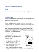
5 Architecture
Figure 1 shows the architecture of the ZAF and its relation to the hardware and the Z-Wave protocol.
Hardware & Z-Wave Protocol
Application
Z-Wave Framework
Transport Layer
Command Classes
Utilities
Figure 1. The Z-Wave Plus Application Framework Architecture
The ZAF consists of three blocks:
Transport Layer:
This layer handles all communication with the protocol, which includes single cast, multicast,
Multi-Channel encapsulation, delivery of bundled commands, etc.
Command Classes:
These modules parse and compose Command Class frames.
Utilities:
Utilities are composed of different modules including those that are used for handling I/O
communication specific for the WSTK and BRD 8029 boards bundled with the SDK. Other
modules are battery monitoring and firmware updating, etc.
The framework implements an event-driven application design.
The framework provides built-in features for developing simpler applications. Transmit buffers are
mutex-protected to ensure that the application has only one transmit request job (unsolicited event) at
a time. The transmit buffer is released only when the transmit request job is completed or has timed
out. The Framework can handle one request job and one response job at the same time.

INS14259-11 Z-Wave Plus V2 Application Framework SDK7 2020-06-17
silabs.com | Building a more connected world.
Page 8 of 54
The ZAF is split into the following two folders:
/CommandClasses/ contains CC modules. All CC modules share a protected transmit buffer
provided by the ZW_tx_mutex module. The ZW_tx_mutex module implements two transmit
buffers, one for request calls and one for response calls.
/ApplicationUtilities/ contains utility modules and interfaces to the transport layer. Some
of the modules are used for simple MMI-setup such as button and LED handling. Other modules
like association_plus, battery_monitor, battery_plus, and ota_util are more complex utility
modules which interface to CC and the client application.
5.1 Application Memory Constraints
The following memory resources are available for certified application development including Z-Wave
Framework and Utilities:
64 kB of Flash memory for executable code
8 kB of RAM for temporary data
The above limitations MUST NOT be exceeded. Violating the limitations may impair compatibility with
future SDK versions.
The code space usage for the distributed certified applications are given as example for the beta
release:
Application
SDK 7.00.00 Beta
Binary Total
Application
Framework
(ZAF)
Utilities
(Components)
DoorLockKeyPad
180256 bytes
4139 bytes
24197 bytes
2326 bytes
Powerstrip
186064 bytes
3832 bytes
28259 bytes
2326 bytes
SensorPIR
181884 bytes
2546 bytes
26559 bytes
2326 bytes
SwitchOnOff
177684 bytes
2211 bytes
22667 bytes
2326 bytes
WallController
179788 bytes
3355 bytes
22907 bytes
2326 bytes
The certified DoorLockKeyPad application need 4139 bytes + 24197 bytes + 2326 bytes = 30662 bytes out
of the 64 kB allocated for the Application, Framework and Utilities. In addition, a separate OTA buffer is
allocated for firmware update.
The bootloader resides in separate 10 kB storage area and is not part of the certified application.
Note: The numbers listed under sub-modules (the last three columns) are the raw object file code sizes.
The linker will remove unused functions/code and result in a slightly smaller actual code space usage.
The application code space usage can be found in the .map file in Simplicity Studio:
https://www.silabs.com/community/mcu/32-bit/knowledge-base.entry.html/2016/03/07/interpreting_thegcc-BpRD

INS14259-11 Z-Wave Plus V2 Application Framework SDK7 2020-06-17
silabs.com | Building a more connected world.
Page 9 of 54
5.2 Smart Start
The Smart Start feature is part of the protocol and automatically handles the inclusion process without
having a user physically interact with a device. When powered on for the first time, the device tells the
world that it is ready for inclusion and most likely a controller nearby will hear this and include the
device. If inclusion process times out, it retries again after a given time.
5.2.1 Starting smart start inclusion
The Smart Start inclusion process starts when the application invokes “ZAF_setNetworkLearnMode()”
with the parameter “E_NETWORK_LEARN_MODE_INCLUSION_SMARTSTART”.
The Z-Wave protocol informs the application about the status of inclusion using the command status
handler with the following events:
EZWAVECOMMANDSTATUS_NETWORK_LEARN_MODE_START
EZWAVECOMMANDSTATUS_LEARN_MODE_STATUS
The EZWAVECOMMANDSTATUS_NETWORK_LEARN_MODE_START event contains a status telling
whether the inclusion was started successfully.
The EZWAVECOMMANDSTATUS_LEARN_MODE_STATUS event can contain several different statuses:
ELEARNSTATUS_SMART_START_IN_PROGRESS
ELEARNSTATUS_LEARN_IN_PROGRESS
ELEARNSTATUS_ LEARN_MODE_COMPLETED_FAILED
ELEARNSTATUS_ LEARN_MODE_COMPLETED_TIMEOUT
ELEARNSTATUS_ ASSIGN_COMPLETE
The status ELEARNSTATUS_SMART_START_IN_PROGRESS indicates that the process of smart start
inclusion to a controller has commenced.
The status ELEARNSTATUS_LEARN_IN_PROGRESS indicates that the process of classic inclusion to a
controller has started.
If the status is ELEARNSTATUS_ LEARN_MODE_COMPLETED_FAILED, the application must reset its NVM
and reboot.
If the status is ELEARNSTATUS_ LEARN_MODE_COMPLETED_TIMEOUT, the application must re-enter
the Smart Start inclusion process.
5.2.2 Configuring smart start inclusion
When an end device is in smart start it will send out several inclusion request with increasing delay
between. By default, the maximum inclusion request interval is set to 512 seconds.
The maximum inclusion interval can be changed from the application. A higher value might be used in
battery powered products to save battery power if it is expected that the product will be in smart start
inclusion for a long time. A lower value might be used to ensure a faster smart start inclusion when
power consumption is not an issue.

INS14259-11 Z-Wave Plus V2 Application Framework SDK7 2020-06-17
silabs.com | Building a more connected world.
Page 10 of 54
The command for changing the maximum inclusion interval is:
Function:
- void ZAF_SetMaxInclusionRequestIntervals(uint32_t intervals)
Function for setting the maximum inclusion request delay.
Parameter:
- uint32_t intervals
Maximum inclusion request delay in 128 seconds steps. Valid range is 5-99
The inclusion requests will be sent out on interval shown in the table below:
Request number
Delay since last inclusion request
0 (Power up)
0 sec
1
Random(0..16 sec)
2
Random(16..32 sec)
3
Random(32..64 sec)
4
Random(64..128 sec)
5
Random(128..256 sec)
6
Random(256..512 sec)
..
..
X
Random(Interval*64..interval*128 sec)

INS14259-11 Z-Wave Plus V2 Application Framework SDK7 2020-06-17
silabs.com | Building a more connected world.
Page 11 of 54
5.3 Power Management
Power management is handled by the Z-Wave protocol. All listening nodes are prevented by the
protocol from entering any energy mode other than EM0 and EM1. Frequently listening (FLiRS) nodes
can enter energy modes EM0-EM2, while non-listening nodes can enter the EM0-EM2 modes and the
EM4-hibernate mode.
A new module is introduced in the ZAF/ApplicationUtilities called PowerManagement. This module is
used to communicate to the protocol if a FLiRS or non-listening application wants to stay awake for a
given time. The module makes it possible to register so-called Power Locks that when enabled prevent
the processor from going into a low power mode. A power lock can be set to time out after a selectable
number of milli seconds or can be enabled indefinitely until cancelled by a new function call. (Indefinite
power locks are enabled by setting the timeout value to zero.)
Power Locks are registered in one of two types of configurations described in the table below:
Power Lock configuration
Description
PM_TYPE_RADIO
Prevents FLiRS and non-listening nodes from entering other
energy modes than EM0 and EM1. This means that the radio
transceiver will stay operational.
PM_TYPE_PERIPHERAL
Prevents non-listening nodes from going to deeper sleep
than EM2. The radio transceiver is not operational in EM2
but the Low Energy Peripherals are.
For further details, refer to section 8.6.
5.4 True Status Module
The True Status module implements the requirements for Lifeline Reports as specified in document “Z-
Wave Plus v2 Device Type Specification” [15].
The main components of the True Status module are described in the following sub-sections.
5.4.1 True Status Engine (TSE)
The True Status Engine component is located in the ZAF_ApplicationUtilities_TrueStatusEngine folder
and consists of the following source files:
ZAF_TSE.c
ZAF_TSE.h
TSE implements the functionality for registering and handling the state change events that a node
wants to report to its lifeline association group members.

INS14259-11 Z-Wave Plus V2 Application Framework SDK7 2020-06-17
silabs.com | Building a more connected world.
Page 12 of 54
A state change can be triggered by a command from a remote note, or by a local change (e.g., a button
press).
Public functions:
- bool ZAF_TSE_Init();
Function for initializing the True Status Engine. Called by the ZAF during initialization.
- bool ZAF_TSE_Trigger(void* pCallback, void* pData, bool overwrite_previous_trigger);
Function for registering state change events and triggering the report to be sent to lifeline
group members after a predefined delay. The delay is currently defined to 250 ms. The delay is
a means to prevent network collisions and to avoid generation of redundant reports from rapid
state changes.
The function also takes care of sending the report to the relevant lifeline group members only;
i.e., it will not send the report to a lifeline destination that issued the command causing the
state change. The current implementation can hold up to 3 different state change requests in a
queue awaiting the predefined delay to expire. Additional requests during this period will be
discarded.
Arguments:
- pCallback: Pointer to a callback function for sending the state change report to the lifeline
group members. (Described in more details in the next section).
- pData: Pointer to a data struct that will be passed in argument to the pCallback function. The
pData pointed struct MUST first contain a RECEIVE_OPTIONS_TYPE_EX variable indicating
properties about the received frame that triggered the change. Local changes must also include
a RECEIVE_OPTIONS_TYPE_EX in the pData struct.
- overwrite_previous_trigger: Boolean parameter indicating if a previous trigger with the same
pCallback and the same source endpoint in the pData struct should be discarded or not. Set it to
true to overwrite previous triggers and false to stack up all the trigger messages.
Returns true if success. False if the request could not be handled (queue is full).
5.4.2 True Status Callback Functions
The True Status Callback Functions consist of several functions that implement the functionality for
sending the actual state change reports to the lifeline association group members. These functions are
implemented in each of the relevant command class modules.
The True Status Callback Function is one of the arguments passed to the ZAF_TSE_Trigger() function
(described in the previous section), and it will be executed by the True Status Engine for sending the
state change reports to each of the relevant members of the lifeline group, one at a time.
An example of a True Status Callback Function implementation can be found in the Command Class
BinarySwitch:
void CC_BinarySwitch_report_stx(TRANSMIT_OPTIONS_TYPE_SINGLE_EX txOptions,
s_CC_binarySwitch_data_t* pData);

INS14259-11 Z-Wave Plus V2 Application Framework SDK7 2020-06-17
silabs.com | Building a more connected world.
Page 13 of 54
Arguments:
- txOptions: Tx Options passed from the True Status Engine with the required destination
parameters for sending the state change report to a given lifeline member.
- pData: Pointer to the data struct previously registered at the call to ZAF_TSE_Trigger().
Contains the command data for the report to be sent.
It is important to note that a True Status Callback Function must only send the state change reports by
single-cast addressing, not by multicast. Therefore, be sure to use only the Transport_SendRequestEP()
transmit function for this purpose as it is also done in the CC_BinarySwitch_report_stx()
implementation.
5.4.3 True Status Sequence Flows
The following diagrams show the function call flows for a BinarySwitch example for the two use cases:
1) state change triggered by a command from a remote note, and 2) state change triggered by a local
change (e.g., a button press).

INS14259-11 Z-Wave Plus V2 Application Framework SDK7 2020-06-17
silabs.com | Building a more connected world.
Page 14 of 54
5.4.3.1 Use Case 1 – State Change Triggered by a Command from a Remote Note
CC BinarySwitch
True Status
Engine
SW Timer
State change
command from
remote
ZAF_TSE_Trigger(pCallback, pData, true);
OK
Puts trigger
in queue
Starts timer
Timer expires
250
ms
CC_BinarySwitch_report_stx(txOpts, pData)
Send report(s)
TSE calls the
CC_ function for
each destination
in lifeline

INS14259-11 Z-Wave Plus V2 Application Framework SDK7 2020-06-17
silabs.com | Building a more connected world.
Page 15 of 54
5.4.3.2 Use Case 2 – State Change Triggered by a Local Change
CC BinarySwitch
True Status
Engine
SW Timer
Application
Local state
change (e.g. by
button press)
ZAF_TSE_Trigger(pCallback, pData, true);
OK
Puts trigger
in queue
250
ms
Starts timer
Timer expires
CC_BinarySwitch_report_stx(
txOpts, pData)
Send report(s)
TSE calls the
CC_ function for
each destination
in lifeline
/