Page is loading ...

WARRANTY.....Top Flite Models guarantees this kit to be free of defects in both
material and workmanship at the date of purchase. This warranty does not cover any component parts
damaged by use or modification. In no case shall Top Flite's' liability exceed the original cost of the
purchased kit. Further, Top Flite reserves the right to change or modify this warranty without notice.
In that Top Flite has no control over the final assembly or material used for final assembly, no
liability shall be assumed nor accepted for any damage resulting from the use by the user of the final
user-assembled product. By the act of using the user-assembled product the user accepts all resulting
liability.
If the buyer is not prepared to accept the liability associated with the use of this product, he
is advised to immediately return this kit in new and unused condition to the place of purchase.
Top Flite Models
P.O. Box 788
Urbana, IL 61801
Technical Assistance - Call (217)398-8970
P516P03 V1.0
READ THROUGH THIS INSTRUCTION BOOK FIRST. IT CONTAINS IMPORTANT INSTRUCTIONS AND WARNINGS CONCERNING THE ASSEMBLY AND USE OF THIS MODEL.
USA
MADE IN
TM

METRIC CONVERSION CHART ............2
INTRODUCTION.....................................3
Precautions ..........................................3
DIE PATTERNS.....................................4,5
DECISIONS YOU MUST MAKE EARLY IN
THE BUILDING SEQUENCE..................6
Engine and Mount Selection.................6
Supplies and Tools Needed..................6
Other Items Required...........................7
Common Abbreviations ........................7
Types of Wood......................................7
Tips for Competition-Minded Modelers.7
GET READY TO BUILD..........................8
Build the Tail Surfaces..........................8
Build the Fin ........................................11
Build the Rudder..................................12
Build the Wing.....................................13
Join theWing Panels............................18
Sheet the Wing....................................21
Build the Fuselage...............................25
Tips for Silver Soldering ......................28
Mount the Wing to the Fuselage..........32
Attach the Stab and Fin.......................34
Prepare the Elevators..........................36
Fuselage Completion...........................37
Install the Dorsal Fin............................40
Make the Top Cowling.........................41
Mount the Cowling...............................43
Build the Wing Fillet.............................43
Install the Forward Wing Fairing..........45
Fit the Radiator....................................46
Operational Flaps................................46
FINISHING.............................................49
Final Sanding ......................................49
Fuel Proofing.......................................49
Balancing the Plane Laterally..............49
Covering..............................................49
Apply Trim ...........................................50
Exhaust Stacks....................................51
Apply Decals .......................................51
Hinging................................................51
Final Control Hardware Hookup ..........52
Mount the Landing Gear......................53
Fixed Landing Gear.............................53
Retracts...............................................53
Cockpit Finishing.................................53
Install Receiver, Switch and Battery ....54
Balance Your Model.............................54
Final Hookups and Checks..................55
Control Surface Throws.......................55
PRE-FLIGHT..........................................56
Charge the Batteries ...........................56
Find a Safe Place to Fly ......................56
Ground Check the Model.....................56
Range Check your Radio.....................56
Engine Safety Precautions ..................56
AMA SAFETY CODE.............................56
General ...............................................56
Radio Control ......................................57
FLYING ..................................................57
2-VIEW DRAWINGS ..............................60
METRIC CONVERSIONS
1” = 25.4 mm (conversion factor)
1/64” = .4 mm
1/32” = .8 mm
1/16” = 1.6 mm
3/32” = 2.4 mm
1/8” = 3.2 mm
5/32” = 4 mm
3/16” = 4.8 mm
1/4” = 6.4 mm
3/8” = 9.5 mm
1/2” = 12.7 mm
5/8” = 15.9 mm
3/4” = 19 mm
1” = 25.4 mm
2” = 50.8 mm
3” = 76.2 mm
6” = 152.4 mm
12” = 304.8 mm
15” = 381 mm
18” = 457.2 mm
21” = 533.4 mm
24” = 609.6 mm
30” = 762 mm
36” = 914.4 mm
- 2 -
TABLE OF CONTENTS

- 3 -
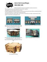
INTRODUCTION
Thank you for purchasing the Top Flite
GOLD EDITION
P-51D Mustang.
The Top Flite P-51D is an excellent sport
scale model that is just as “at home” with sport
flying as it is in competition. Its exact scale
outline allows you to add authentic details and
take it into serious competition if desired. Its
modern construction and refined aerodynamics,
incorporating features such as computer-
designed airfoils that progressively change from
root to tip with built-in washout, give you a plane
that will build straighter and fly better than warbird
kits of the past.
The Gold Edition Mustang is approximately
1/7th scale. The exact scale ratio is 1: 6.83. The
trim scheme allows you to finish a very
impressive model using Top Flite Super
MonoKote®. The MonoKote covered prototype,
shown on the box, was good enough to finish 2nd
in Expert at the very competitive 1992 Blue
Grass Scale Classic in Kentucky. It scored quite
well in static due to its excellent outline, and
posted the highest flight scores in the expert
category. This performance earned the Mustang
an invitation to the 1992 Scale Masters.
Please inspect all parts carefully before
starting to build! If any parts are missing,
broken or defective, or if you have any
questions about building or flying this model,
please call us at (217) 398-6300 and we’ll be
glad to help. If you are calling for replacement
parts, please look up the part numbers and
the kit identification number (stamped on the
end of the carton) and have them ready when
calling.
PRECAUTIONS
1. You must build the plane according to the
plans and instructions. Do not alter or modify
the model, as doing so may result in an unsafe or
unflyable model. In a few cases the plans and
instructions may differ slightly from the photos. In
those instances you should assume the plans and
written instructions are correct.
2. You must take time to build straight true and
strong.
3. You must use a proper R/C radio that is in
first class condition, the correct sized engine and
correct components (fuel tank, wheels, etc.)
throughout your building process.
4. You must properly install all R/C equipment
and other components so that the model operates
properly on the ground and in the air.
5. You must test the operation of the model
before the first and each successive flight to
insure that all equipment is operating, and you
must make certain that the model has remained
structurally sound. Be sure to check external
nylon clevises often, and replace any that show
signs of wear.
6. If you are not already an experienced R/C pilot
at this time, you must fly the model only with the
competent help of a well experienced R/C pilot .
NOTE: We, as the kit manufacturer,
can provide you with a top quality kit
and thorough instructions, but
ultimately the quality and flyability of
your finished model depends on how
you build it; therefore, we cannot in
any way guarantee the performance of
your completed model, and no
representations are expressed or
implied as to the performance or
safety of your completed model.
Remember: Take your time and follow
directions to complete a well-built model that
is straight and true.
WARNING! THIS IS NOT A TOY!
The model you will build from this kit is not a toy! It is capable of serous bodily
harm and property damage. IT IS YOUR RESPONSIBILITY AND YOURS ALONE -
to build this kit correctly, properly install all R/C components to test fly the model, and
fly it ONLY with experienced, competent help in accordance with all safety standards
as set down in the Academy on Model Aeronautics Safety Code. It is suggested that
you join the AMA to become properly insured before you attempt to fly the model. IF
YOU ARE JUST STARTING R/C MODELING, CONSULT YOUR LOCAL HOBBY
SHOP OR WRITE TO THE ACADEMY OF MODEL AERONAUTICS TO FIND AN
EXPERIENCED INSTRUCTOR IN YOUR AREA.
Academy of Model Aeronautics
5151 East Memorial Dr.
Muncie, IN 47302-9252 (800) 435-9262


SUGGESTED SUPPLIES AND TOOLS
❏ 2 oz. Thin CA
❏2 oz. Medium CA
❏2.5 oz. 5-Minute Epoxy
❏2.5 oz. 30-Minute Epoxy
❏Hand or Electric Drill
❏Drill Bits: 1/16”, 3/32”, 1/8”, 5/32”, 3/16”,
13/64”, 1/4”, 5/64" & 17/64”
❏Sealing Iron (Top Flite)
❏Heat Gun (Top Flite)
❏Hobby Saw (X-Acto Razor Saw or Coping
Saw)
❏X-Acto Knife, #11 Blades
❏Pliers
❏Screw Drivers
❏T-Pins
❏Straightedge with measuring scale
❏Masking Tape (Required for construction)
❏Sandpaper (coarse, medium, fine grit)*
❏T-Bar Sanding Block (or similar)
❏Waxed Paper
❏Lightweight Balsa Filler (such as Hobbico
HobbyLite™)
❏1/4-20 Tap, Tap Wrench
❏Isopropyl Rubbing Alcohol (70%)
❏Dremel Moto Tool or similar (optional)
NOTE: On our workbench, we have
four 11” T-Bar sanders, equipped with
#50, #80, #150 and #220-grit
sandpaper. This setup is all that is
required for almost any sanding task.
Sanding blocks can be made from
balsa for sanding hard to reach spots.
We also keep some #320-grit wet-or-
dry sandpaper handy for finish
sanding before covering.
- 6 -
DECISIONS YOU MUST MAKE EARLY
IN THE BUILDING SEQUENCE
ENGINE AND MOUNT SELECTION
The recommended engine size range is as
follows:
.60 to .91 cu. in. (10cc to 15cc) 2-cycle
.90 to .120 cu. in. (15cc to 20cc) 4-cycle
The Mustang will fly well with any of the
recommended engines. The 4-cycle engines
and most .90 2-cycle engines will turn a larger
prop at lower RPM’s. This is often desirable for
scale realism. Many .60 2-cycle engines
produce about as much horsepower as the
popular .90 2-cycle engines and will fly the
Mustang fine. If you use a .60 2-cycle, a
Schnuerle ported engine is preferred.
If you will be side mounting your engine,
the 2-cycle engines will not stick out of the cowl
as much as 4-cycles will. If you mount your
engine inverted, you will need to provide ample
cooling air entry and exit areas.
This kit includes an EM60120 engine
mount that will hold most engines in the
recommended size range. The Top-Flite In-Cowl
exhaust system works very well in the Mustang
when the engine (2-Stroke) in mounted inverted.
RETRACTS
The choice whether or not to use fixed
gear or retracts is up to you. Retracts offer
good looks and great flight realism at the cost of
some expense and complication. For sport
flying and moderate competition work we
recommend you choose an air operated system
such as the Robart #605 90-degree retracts.
These offer the easiest installation and reliable
operation. Mechanical retracts could be fitted,
but the length and weight of the tire/strut
assembly would overload most servos. More
information on retracts is found in the “Tips for
Competition-Minded Modelers” section and in
the construction sequence. A Robart retractable
tail gear will work well and may be mounted to
F-10 (you must modify the lightening holes in F-
10). You must actuate the tail gear retract with
a servo or a 3/8” air cylinder and add a pull-pull
tail wheel steering system to your model.
Century Jet Models also offers a retract/strut
package that is specifially tailored for the P-51.
WHEEL SELECTION
The scale tire size is 4”. The
recommended range of tire sizes is 3-1/4” to 4”.
If you use fixed gear, you may choose to use
the smaller tires to reduce drag in the air. If you
use 3/8” offset Robostruts, they are only
available to fit up to 3-1/4” tires at the time of
this writing. Robart main wheels are very close
to scale for a P-51. A 1-1/4” tail wheel is scale
and recommended.
FLAPS
This model is designed with all the
provisions in place to iinclude operating flaps
that are very scale. They require some
craftsmanship and time but are not very difficult
to install, if you follow the instructions. They
enhance the model’s flight characteristics and
scale appeal while causing no bad effects. No
trim correction of any kind is needed when they
are used with the recommended throws. The
flaps require one channel, a Y-harness, and two
standard or mini servos. They are highly
recommended for those who wish to install
them. More information on the use of the flaps
may be found in the flying section.

COMMON ABBREVIATIONS USED IN
THIS BOOK AND ON THE PLANS:
deg.= Degrees Ply = Plywood
Elev= Elevator Stab = Stabilizer
Fuse= Fuselage " = Inches
LE= Leading Edge (front) Rt = Right
LG= Landing Gear Lt = Left
TYPES OF WOOD
TIPS FOR COMPETITION-MINDED
MODELERS
COUNTERBALANCES
The elevator and rudder counterbalances may
be added for scale appearance. They do not
affect the flight performance. Their locations and
sizes are dashed in on the plans.
SCALE RETRACTS AND DOORS
The retract landing gear pivot location shown
on the plans is basically correct. The stance of the
model (and strut length) shown with the gear down
is correct. Keep in mind that the Mustang's gear,
like that in most modern aircraft, compresses
under the weight of the aircraft and extends when
the aircraft takes off. This fact means that the rigid
struts commonly used on models will not fold into
the scale locations. The only reasonable way to
overcome this problem is to use oleo struts (such
as Robart Robostruts) that have springs light
enough to compress under the weight of the model
and thus function in a scale fashion.
If you should choose to modify your kit to
include very scale retracts and doors, most of the
work is up to you. Fully cycling gear doors
require much preplanning, excellent
craftsmanship, and are generally expensive. We
can, however, offer a few hints:
1. Bob Violett Models’ T-33 main landing gear
retracts may be a good place to start for the
following reasons.
- 7 -
OTHER ITEMS REQUIRED
Four to six channel radio with 4 to 7 servos.
Engine (see page 6 and the box side panel)
Engine Mount (see page 6)
Propellers (see engine instructions for recommended sizes). Note: The 4-blade prop shown on the
front of this manual is specially made for display purposes from two wooden props and is not usable
for actual flight.
Pilot figure (1/7 or 2” scale recommended)
4” (102mm) P-51 Spinner (CB #5103 (red), #5105 (black), #5106 (white) recommended)
Fuel Tank (Most 10 to 14 oz. (296cc to 415cc) tanks will fit)
3-1/4” (83mm) to 4” (102mm) Main Wheels (2) (see page 6)
1-1/4” (32mm) Tail wheel (see page 6)
3/16” (4.8mm) Wheel Collars (4 for fixed gear main wheels)
3/32” (2.4mm) Wheel Collars (2 for tail wheel)
Top Flite®Super MonoKote®(2 rolls) Aluminum plus Red, White, Black, and Olive Drab shown
Silicone Fuel Tubing
Latex Foam Rubber Padding (Hoibbico® 1/4” thick foam)
Optional:
Retracts ..................Robart #605
Air Control Kit............Robart #188
Hinge Points (for flaps)...Robart #309
Robostruts................Robart #653 L&R
SCALE DOCUMENTATION
This model was designed using the Koko-
Fan 3-view drawings as the reference for
outline. This fact makes it preferable to use
those drawing for scale documentation.
The drawings and many Mustang photo
packs are available from:
Scale Model Research
2334 Ticonderoga Way
Costa Mesa, CA 92626
(714) 979-8058

“Photos of Violett T-33 main landing gear and
suggested 1/4” plywood aft mounting rail”
a. They are very low profile and can be
buried in the wing deeply enough to leave room
for outer doors.
b. They lock down in a position that is angled.
Therefore, they compensate for some of the
dihedral in the P-51 wing.
c. They have a pivot block strut hole diameter
that directly accepts Robostruts when shimmed
with a piece of K&S brass 13/32” O.D. tubing.
d. They do not have an uplock and therefore
can pull the strut and tire farther than 90 degrees
and fully into the wheel wells.
e. Use 5/8” I.D. Robart air cylinders mounted
inboard of the retracts to actuate these units.
These cylinders have enough power to lift and
hold the long strut and heavy tire.
REMEMBER: A retract and strut like this is a
very rigid unit. This gives excellent ground
handling, but requires strong mounts.
2. 4-inch wheels are the closest to scale.
However, offset struts to hold 4” wheels may be
hard to find. Robart makes an offset strut to hold
their 3-1/4” wheel, which works well and looks
close to scale. Robart may offer struts for 4”
wheels at some time after this writing.
3. Bob Violett Models has offset door hinges
that are excellent for hinging inner main landing
gear doors. They also offer small scale-looking
air cylinders that are specifically designed for
actuating landing gear doors. The real Mustang’s
inner doors are closed during take off and
landing. When “gear-up” is selected, they open,
allow the wheels to come in, then close again.
Duplicating this action requires either 2-channels,
or a very tricky mechanism. The inner doors on
the real aircraft would often fall open when the
engine was off and hydraulic pressure was lost.
4. The holes for the forward wing mounts may be
drilled so the 1/4 -20 nylon bolts are concealed
under the inner doors.
________________________________________
________________________________________
GET READY TO BUILD
1. Unroll the plan sheets. Re-roll the plans
inside out to make them lie flat.
2. Remove all parts from the box. As you do,
figure out the name of each part by comparing it
with the plans and the parts list. Using a felt tip or
ball point pen, write the part name or size on
each piece to avoid confusion later. Use the die-
cut patterns shown on pages 4 and 5 to identify
the die-cut parts and mark them before punching
out. Save all scraps. If any of the die-cut parts
are difficult to punch out, do not force them!
Instead, first cut around the parts with an X-acto
knife. After punching out the die-cut parts, use
your T-Bar or sanding block to lightly sand the
edges to remove any die-cutting irregularities.
3. As you identify and mark the parts,
separate them into groups, such as fuse
(fuselage), wing, fin and stab (stabilizer), and
hardware.
BUILD THE TAIL SURFACES
1. Work on a flat surface over the plans
covered with waxed paper. Refer to the plans to
identify the parts and their locations.
2. Punch out both sets of the die-cut 3/32”
balsa ribs S-1 to S-6. There are jig tabs on the
bottom edges of these ribs. If any of these break
off, carefully glue them back on with thin CA.
Lightly sand any imperfections. You may need to
finish cutting the notch in the forward portion of
S-1 for the Stab Joiner (SJ) with a knife. Using a
pen, mark the extensions of the bottom edge of
the ribs across the fore and aft jig tabs. These
will aid in centering the Leading and Trailing
Edges.
3. The Stab Trailing Edges (TE’s) are die-
cut from 1/4” balsa. Since some crushing may
happen when die-cutting wood of this thickness,
they are supplied slightly long and can be
trimmed. Smooth the edges of these pieces with
sandpaper.
4. The stab and fin Leading Edges (LE’s)
are made from the 1/4” x 30” tapered balsa stock.
Cut two pieces about 1/4” longer than the length
shown on the plans for the stab LE.
- 8 -

5. Starting with the right half of the stab, pin
ribs S-2 and S-6 to the building board over their
locations on the plans.
6. Center the LE vertically on the front edge
of ribs S-2 and S-6. Glue it in place with CA.
7. Center the TE vertically on the back edge
of ribs S-2 and S-6. Glue it in place with CA.
8. Glue ribs S-3, S-4, and S-5 in their places.
All the jig tabs should rest on the work surface.
9. Trim the LE and TE so they end exactly
over the stab centerline.
10. Repeat steps 5 through 8 to build the left
half of the stab. The left half of the stab is built
next to the right half with the two halves butt
glued together for now.
11. Trim the 1/4” x 7/16” x 4-1/4" hard balsa
stab TE joiner, if necessary, to fit between the
S-2’s. Securely glue it to the TE’s and the S-2’s.
12. Trim the length of the die-cut 1/8”
plywood Stab Joiner (SJ), if required, for a good
fit between the S-2’s. Place the stab joiner into
the slots in the S-1’s and work the whole
assembly into position. Make sure all parts are
properly aligned and the S-1 jig tabs contact the
work surface. Glue in the stab joiner and the S-
1’s.
13. Using medium CA, reinforce any glue
joints that do not look strong.
14. Carefully remove the stab from the
building board but try not to damage the jig tabs,
as they will be useful until after the top of the stab
is sheeted.
15. Use a razor plane and a sanding block to
- 9 -

- 10 -
blend the top surface to the LE (particularly
toward the tip), even with the ribs. Sand the TE,
if required, to blend with the ribs.
TIPS FOR MAKING WING
AND STAB SKINS
A. Whenever possible, pre-join the balsa sheets
to make a “skin” before attaching them to the
structure.
B. Many modelers like to sort the wood to put the
best wood with the most even grain structure on
the top of the wing and stab.
C. Make your skin larger than needed to allow for
misalignment. On a large surface like the wing,
3/8” extra is suggested.
D. To make skins the following steps are
suggested:
1. True up the edges of the sheets with a
metal straight edge and a sharp knife or a “T-Bar”
sanding block.
2. Test fit the sheets together to make sure
they match well.
3. Glue the sheets together with thin CA over
a flat surface covered with waxed paper. I quickly
wipe the joint with a fresh paper towel to remove
excess glue and make sanding easier. Mark the
poorest surface that you think should be the
inside of the sheet with an “I”.
4. Working on a flat surface, sand the skin
with a large flat sanding block and fresh, sharp
220 paper.
5. Trim the perimeter of the sheet to even up
the edges.
16. Make four stab skins from three 1/16” x 3”
x 30” balsa wing sheet pieces. See the sketch for
the proper layout on the wood. Refer to the plans
for the exact shapes and sizes, but remember to
make the skins slightly oversize.
17. Pin the stab structure onto the flat
building surface. Test fit the two skins over the
structure. Make sure the skins meet well at the
center. Adjust them if necessary.
18. Apply an even bead of medium or thick
CA to the top edges of the structure. Place the
skin in its proper position and press it firmly down
until the glue has set. Repeat this step for the
other top skin.
Hint: A small stack of magazines can
be used to hold the sheeting down.
19. Remove the stab from the building board.
Trim off the jig tabs with a sharp knife. Trim and
blend the LE and TE to the ribs as you did before.
Check all glue joints, adding glue as necessary.
20. If you want to modify the stab for the
scale balance tabs or a different hinging
technique, now is the time to add the appropriate
structure. Refer to the plans for the locations and
sizes of the balance tabs (parts not included).

21. It is important to get a good glue bond
between the stab structure and the bottom stab
skins. Apply a heavy bead of medium or thick CA
to all of the bottom edges of the right side of the
stab structure. Place a skin on the structure and
hold it in place with your hands until the glue sets.
Repeat this for the left side. Be careful not to
bend or twist the stab during this step.
22. True up the ends of the stab with a
sanding block. Round the leading edge of the
stab to match the cross section on the plan.
23. Glue on the shaped 5/8" balsa Stab
Tips. Use a razor plane and a sanding block to
shape them to match the stab airfoil. You may
contour the tip to its final shape now, or wait until
the model is nearer completion.
BUILD THE FIN
1. Cut a 9-1/2” length of the tapered 1/4”
balsa stabilizer LE stock left over from the stab.
2. Glue the die-cut 1/4” balsa Fin Forward
and Aft TE’s (FF and FA) together with CA.
Since these pieces are thick and die-cut, they will
probably require a little touch up and blending
with a sanding block.
3. Punch out the die-cut 3/32” balsa ribs V-1
through V-6. Be sure to preserve their jig tabs.
4. Pin ribs V-1 and V-6 to the building board
over their proper locations. Center the LE on the
front of the ribs and glue it in place. Notice that
the fin LE protrudes through the stab into former
F-11.
5. Center the Fin TE on the aft edge of the
ribs and glue it in place.
6. Put ribs V-2 through V-5 into their places
and glue them. Remember, all jig tabs should
contact the work surface.
7. Apply extra medium CA glue to any joints
that do not appear to be well glued.
8. Blend the LE to match the ribs on the
upward facing (left) fin side. Sand the TE if
necessary to blend smoothly with the ribs.
9. Make a skin for each side of the fin using
the 1/16” balsa sheet left over from the stab
skins. See the sketch on page 10.
10. With the structure flat on the table, glue
on the left skin.
11. Trim off the jig tabs and blend the LE and
TE to the ribs on the right side of the fin.
- 11 -

12. If you are adding scale balance tabs, add
the simple additional structure as shown in the
photo. (Parts not included).
13. Glue on the right skin.
14. True up the edges of the fin sheeting with
a sanding block. Shape the LE to match the
cross section on the plans.
15. Glue the shaped 3/4” balsa fin tip to the
top of the fin. Use a razor plane and a sanding
block to do the initial shaping of the tip. Final
shaping should be done later, with the fin taped to
the rudder.
BUILD THE RUDDER
1. Glue the two die-cut 1/4” balsa Rudder
LE’s together with medium CA. Even up the
edges with a sanding block, but save any tapering
for later.
2. Draw a centerline on the aft surface of the
LE. Draw two parallel lines 1/16” away from both
sides of the centerline.
3. Align the die-cut 3/32” balsa Rudder Plate
(RP) over the plans and mark the “Rib” locations
on both sides of the rudder plate. (See the photo
below.)
4. Hold the Rudder Plate centered on the
rudder LE. Apply thin CA to the joint.
5. Glue the two 1/2” thick shaped balsa
Rudder Tips to both sides of the top of the
rudder plate.
6. Glue the two 1/2” thick shaped balsa
Rudder Bases to both sides of the bottom of the
rudder plate.
7. Cut “ribs” from the 3/32” x 1/2” x 30”
balsa sticks and glue them onto both sides of the
rudder at the locations you previously marked.
8. Refer to the photos and the cross sections
- 12 -

on the plans to obtain the shape of the rudder.
Use a razor plane and sanding block to “rough in”
the shape of the rudder. Final shaping and fitting
should be done after the fin is glued onto the
fuselage, but you may wish to tape the rudder to
the fin at this point to blend the tips of both.
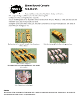
BUILD THE WING
NOTE: The wings are built “UPSIDE-
DOWN” on the plans. The jig tabs are
attached to what is, in the end, the
TOP surface of the wing.
VERY IMPORTANT! Since it is the
standard convention to show the Top
View of the wing, and the wing panels
are built upside-down, the LEFT wing
panel is built over the RIGHT Wing Top
View and vice-versa. This does not
present any problems. Just be sure to
build a left and a right wing.
1. Place the wing plan on your building board
and cover it with waxed paper (you may wish to
cut the wing panel sections of the plan apart to
make handling easier.)
2. Hold the 1/4” x 3/8” x 36” balsa Spars over
the wing plans. Mark the Spars about 1/4” longer
than they need to be. Cut off the spars at the
marks and save the excess for the Flap Servo
Mounts.
3. Punch out all the die-cut 3/32” balsa wing
Ribs. Smooth out any imperfections with
sandpaper. Be sure to keep the jig tabs attached
to the ribs.
4. Ribs W-1 through W-8 have punch marks
just aft of the spar that locate the aileron
pushrods for you. Drill a 3/16” hole at each of
these marks.
5. Drill 1/8” holes through the punch marks in
the two die-cut 1/8” plywood Aileron Bellcrank
Plates (AB). Assemble the bellcrank parts as
shown in the sketch, making a left and a right
plate. Be sure to put a drop of 5-minute epoxy
on the 4-40 nut and threads to prevent the
bellcrank from vibrating loose.
6. Taper one end of each of the four 1/8” x
3/8” x 18” balsa Spar Doublers to match the spar
detail drawing on the plans. Glue a Spar Doubler
to each Spar with the root (non-tapered) end of
the doubler aligned with the root end of the Spar.
7. Center the die-cut 3/16” balsa Aft
Aileron Trailing Edge (A) on the die-cut 3/16”
balsa Forward Aileron Trailing Edge (F) and
glue them together with thin CA. Use a sanding
block to taper the two pieces slightly as shown in
the cross sectional drawing on the plan. These
pieces are die-cut slightly long to allow you to trim
off any imperfections.
- 13 -

8. Pin a Spar assembly to the building
board at three or four locations using the cross-
pinning technique shown in the sketch with the
Doublers up.
9. Glue the die-cut 3/32” balsa ribs W-2
through W-12 to the Spar. These should be
vertical and aligned over their appropriate
locations as indicated on the plans. The jig tabs
located near the aft end of the ribs should all
contact the work surface.
10. Glue the aileron Trailing Edge
assembly to the aft edge of ribs W-8 through
W-12. The upward facing edges of the ribs and
the Trailing Edges should be even and the jig
tabs should all be touching the work surface
during this step.
NOTE: The inboard end of the aileron
TE extends approximately 15/16”
inboard of rib W-8, as shown on the
plan.
11. Glue the lower 1/8” x 3/16” x 21” balsa
TE Spar as far forward as possible in the slots in
ribs W-2 through W-8.
12. Glue the lower 1/8” x 1/8” x 21” balsa
Flap LE into the aft portion of the slots in ribs W-
2 to W-7. There should be a 1/16” gap between
the TE spar and the flap LE.
13. Repeat steps 11 and 12 for the slot in
the upper side of the ribs.
14. Glue the 1/2” x 21” tapered balsa
- 14 -

Flap TE to ribs W-2 and W-7. The flap TE
should be centered on the aft edges of the ribs
and should protrude straight back (see the cross-
sections on the wing plan). Make sure all the jig
tabs are contacting the table. A metal straight
edge can be placed on the structure over the jig
tabs to hold them all down.
15. Sight down the TE of the wing from
the root end, making sure all the ribs are aligned
at the same height. Use paper to shim under any
low jig tabs. Glue the Flap TE to the remainder of
the ribs.
16. Work the upper spar assembly into
place. Make sure it fits well. Put some weights
on top of the structure to make sure it is firmly on
the work surface. Use CA to glue in the top spar.
17. Use a razor saw to put a V-notch in the
shaped balsa Leading Edge to allow it to “bend”
(break) at R-4. Use the LE detail drawing on the
wing plan for reference.
18. Hold the LE centered vertically on the
front edge of the ribs. Use CA to glue it in place.
19. Use thick CA to glue in the die-cut 1/8”
plywood Landing Gear Doublers. Since the
wing panels are built upside-down, the “openings”
in the doublers should face upwards as shown in
the photos. The right side wing plan shows the
placement of the two doublers for retract gear (Z-
4 and Z-5). The left side wing plan shows the
placement of the three fixed gear doublers (G-3,
G-4, and G-5).
Retract Doublers shown
20. Use a sharp knife to trim the balsa ribs
to match the cut-outs in the doublers.
- 15 -

21. If you are going to use flaps, trim the
1/4” x 3/8” balsa stock left over from the wing
Spars to the length shown on the plans for the
flap servo bay rails. Glue the rails into the
notches in W-2 and W-3 with CA. If you do not
plan to use flaps, you may fill the notches with
scrap wood or put the rails in anyway.
22. Glue the aileron bellcrank assembly
into the slots in ribs W-8 and W-9. The bellcrank
should face upwards as shown in the photo.
23. Fit, then glue, in the die-cut 3/32” balsa
Flap Tip Rib at the location shown on the plans.
24. If you plan to use flaps, fit and glue in
the two die-cut 3/32” balsa Flap Root Ribs. Use
a scrap piece of 1/16” balsa to space the root ribs
apart. If you are not using flaps, these parts may
be glued in anyway, or discarded.
25. Custom fit 1/16” balsa Shear Webs to
fit behind the spar between ribs W-3 to W-12.
Glue them to the spars with medium CA. Wick
thin CA into all the joints of the shear webs and
the spars to make sure they are well bonded. It is
not important to glue the shear webs to the ribs.
26. Fit and glue a shear web to the front
of the spars between ribs W-3 and W-4 for extra
strength.
27. Sight down the wing trailing edge to
make sure it is still straight. Shim any low jig tabs
if required. Trim each of the 1/16” x 3” x 3/4”
balsa Aft Shear Webs to fit between ribs W-2
through W-8 in front of the TE Spar. Glue them in
place with the structure held firmly on your flat
work surface.
28. Cut a 16-1/2” long piece of Outer
Pushrod Tube. Roughen the outside of the tube
with 220 grit sandpaper. Feed the tube through
the holes in the ribs as shown on the plans. Use
CA to glue the tube to the ribs.
29. Cut five lengths of Inner Pushrod
Tube about 5/16” long. Slide them onto an .074”
x 34” Threaded End Pushrod Wire at the
intervals shown on the plans. Carefully apply a
small drop of CA to the short tubes if they are not
very snug on the wire.
30. Securely snap a nylon clevis onto the
- 16 -

bellcrank. Feed the wire assembly into the wing
and screw the threaded end well into the clevis.
Hint: The wire is extra long. After the threaded
end starts threading into the clevis, you may bend
over the excess wire and use it as a handle to
turn the wire the rest of the way into the clevis.
Be sure to hold the clevis securely with pliers
while threading the wire into it to keep from
stressing the clevis pin. Cut off the excess wire
flush with the root end of the spar.
31. Use the die-cut plywood 93 deg. tool
(93) as shown to mark the ends of the spars and
TE’s.
NOTE: When marking the spars, the
corner of the tool is on the wing
centerline. When marking the TE
spars and flap LE's, the corner of the
tool is positioned where the TE spars
end on the plan.
DO STEPS 32 AND 33 IF YOU ARE BUILDING
OPERATING FLAPS.
32. Glue the die-cut 1/8” plywood Flap
Horn Base (FH) in its place between W-2 and
W-3. Note how it is flush with the upward facing
edge of the ribs.
33. Cut pieces approximately 1” long from
the 1/2” x 3/4” x 12” balsa stick provided to act as
flap hinge blocks. These are shown on the right
wing panel plan. Some custom fitting of these,
such as tapering, is required. Skip to step 36.
DO STEPS 34 AND 35 FOR FIXED GEAR.
34. Glue the 1/2” x 3/4” x 6-3/4” slotted
hardwood Landing Gear Rail and the 1/2” x 3/4”
x 1-1/2” maple LG Block with a generous amount
of epoxy. Their locations are shown on the left
wing panel drawing. Drill a 3/16” hole through the
rail and block at the location shown on the plan,
to allow the landing gear wire to be inserted.
- 17 -

- 18 -
35. Make any adjustments necessary to
allow the bent wire main landing gear to slide
properly into place.
.
DO STEPS 36 - 39 FOR RETRACT GEAR.
36. Slide the 1/4” x 3/8” x 3-3/4” plywood
Retract Gear Rails into the slots in W-4 and W-5.
Test fit your retracts between the rails. If the rail
spacing is not correct (it should be for most
retracts) adjust the aft slots.
37. Manually extend and retract the gear,
noting the strut angle. Adjust the depth of the
slots if necessary to give a satisfactory angle
when the gear is retracted and extended. It will
be necessary to cut a slot in R-3 for the strut to
pass through.
38. Use generous amounts of 30 minute
epoxy to glue in the rails.
39. Mark and drill the retract mounting
holes in the retract rails.
Repeat steps 7 to 39 to build the other wing
panel.
NOTE: At this point you may remove
the wing panels from the building
board if you have not already done so.
Try to store your panels on a flat
surface with some weights on top of
them until they are joined and sheeted,
to prevent warping.
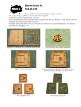
JOIN THE WING PANELS
1. Trim the ends of the spars, LE’s, and TE’s
of both panels very close to the tip rib W-12.
Excess overhang will affect the dihedral angle.
2. Draw a centerline on both W-2’s as shown
in the photos.
3. Trim all the spars at the root end of the
wing as they were previously marked with the 93
degree tool.
4. When you are totally ready to join the
wings, trim off all the jig tabs except those on W-
2and W-12. Use a small sanding block to “clean
up” the area around the tabs.
5. Place the two 3/8” x 1-1/2” x 7-1/2”
Dihedral Jig Blocks under the two W-2 ribs.
Place the wing halves together upside-down.
The spars at W-2 and the W-2 jig tabs on both
panels should rest on the Jig Blocks. The tip
ends of the spars and the W-12 jig tabs rest on
the table (see photo on the next page).

6. Test fit the wing panels on the Jig Blocks
with the two die-cut 1/16” plywood Dihedral
Braces in place. Adjust any parts until the panels
join up nicely at the spars. The die-cut 1/8”
plywood Aft Cross Brace (CB) should be
included in these test fittings. If it requires
trimming, take equal amounts off the right and left
ends.
7. Make two equal length sticks from scrap to
act as spacers between the two W-2’s. These
should be positioned on the W-2 centerline. The
length of these sticks will vary slightly depending
on how your spars are trimmed, but 5-1/2” is a
good starting point (see photo below). These two
sticks will make sure the W-2 ribs are parallel.
8. Test fit the Aft Cross Brace and the sticks
between the two W-2’s and adjust both sticks
equally if adjustment is required. You may notice
that the spars sweep forward slightly. This is
normal.
9. When the wing fits on the Jig Blocks with
the Aft Cross Brace (CB) and the two equal
length sticks in place, it is time to glue it together.
The best method is to use 30 minute epoxy. Coat
the mating surfaces of the spars and dihedral
braces. Then assemble the parts onto the Jig
Blocks. Use CA to tack glue the two equal length
sticks into place as shown in the photos. Use CA
to glue the Aft Cross Brace (CB) into place. Use
masking tape to clamp the dihedral braces to the
spars.
10. Make four 1/16” balsa shear webs to cap
the dihedral braces between W-2 and W-3.
11. Align and glue the die-cut 1/8” plywood
W-1C’s to the die-cut 1/8” plywood W-1B’s, being
sure to make a left and a right.
12. Plug the die-cut 1/8” plywood Aileron
Servo Tray between the two W-1B/C’s. Make
sure all the front edges are aligned. Use a 90
deg. triangle to hold each W-1B/C vertical while
you glue it to the servo tray.
13. Plug the die-cut 1/8” plywood F-8B into
the aft end of the assembly. Check to see that all
edges are square and properly aligned. Use a
hobby knife to make small adjustments to the
notches if required. Use a 90 deg. triangle to
hold the W-1B/C’s vertical while you glue them to
F-8B.
14. Remove the rear stick. Work the
assembly into position in the center of the wing.
Trim the aft spars and flap LE, if necessary, to fit
the assembly. Trim the flap TE as shown on the
plans and in the photos to allow clearance for F-
8B. The photos with steps 17 and 18 show you
the finished assembly.
- 19 -

15. Notice that the W-1 ribs in the assembly
are undersized 1/16” (except the area around the
top of the aileron servo) to allow for a center
doubler of 1/16” balsa center sheeting. Put marks
on the dihedral braces 3/4” both ways from the
center of the wing to aid in the alignment of the
center assembly.
16. The front of the assembly is positioned by
aligning the top edge of the assembly with the top
of the dihedral brace. Tack glue the assembly at
the front edge. NOTE: The word “top” refers to
the top surface of the wing.
17. The back end of the assembly is aligned
by centering the flap TE on the top edge of F-8B
at W-1. The Aft Cross Brace (CB) should
protrude about 1/16” on both sides of the W-1 ribs
to allow for the double sheeting.
18. Thoroughly glue all the joints in the area
of the center assembly with medium CA.
19. Make shear webs for the aft spar
between F-1 and F-2. Glue them to the front of
the aft spar with medium CA.
20. Trim the length of the 1/4” plywood
beveled edge Wing Bolt Plate until it fits between
the two W-2’s near their centerline.
21. Mark a centerline on the Wing Bolt Plate.
Mark two lines offset 3/4” on both sides of the
centerline as shown.
22. Mark the wing bolt hole locations as
shown in the sketch above. Drill 13/64” pilot
holes at the locations marked.
- 20 -
/