Page is loading ...

INSTALLATION GUIDE
EX & RX FRONT BUMPER
FOR JK WRANGLER
AEV30467AA
Last Updated: 04/04/23
PLEASE READ BEFORE YOU START
To guarantee a quality installation, we recommend reading these instructions thoroughly
before beginning any work. These instructions assume a certain amount of mechanical
ability and are not written nor intended for someone not familiar with auto repair.

ii
I. VEHICLE PREPARATION
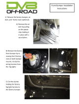
1. Remove factory air dam (fig. 1):
A. Remove the “Scrivet” fasteners at the front and back side of the air dam. Use a Phillips screw-
driver to back out the plastic pin and pull out the fastener. The pin will tend to spin. Use a flat
screwdriver under the base of the fastener to apply pressure as you turn the screw
Figure 1

2. Remove factory bumper (fig. 2).
A. Disconnect fog lights
B. Remove and discard the 8 nuts attaching the bumper to the frame rails.
C. Remove and discard steel backing plates from inside frame rail.
Figure 2

2
3. Modify fog light wiring
A. 2007-2009 USA, CANADA, AND MEXICO MODELS
The fog lights are mounted further apart than factory, so the wiring harness needs to be re-positioned.
This is accomplished by removing the factory conduit and re-routing the harness above the frame rails.
BE CAREFUL NOT TO CUT THE HARNESS!
Remove the tape from the wire harness at both ends to expose the loose length of wires
Extend the harness outboard as much as possible to reach the new fog light location
Replace the conduit, if it has been removed, and re-tape the modified harness
Route the harness along the bottom of the grille and fasten to power steering line using
cable ties
Figure 3
B. 2010+ USA, CANADA, AND MEXICO MODELS
Remove the tape from the wire harness on the right side only to expose the loose length of wire.
Should have approximately 7”
Replace the conduit, if it has been removed, and re-tape the modified harness
Route the harness along the bottom of the grille and fasten to the power steering line using cable ties
Figure 4

3
4. Using a large hammer, flatten the top of the front mounting flange to be parallel with the frame rail (fig. 5).
Drill to 1/2”
Figure 5
5. Drill out the lower mounting hole to 1/2” as shown to allow the bolt to pass through (fig. 6).
Drill to 1/2”
Figure 6

4
6. Re-locate vacuum pump ONLY if installing the AEV Winch Mount.
NOTE: If your model does not have vacuum pump mounted to frame rail, proceed to next step
A. Remove and discard hardware holding the vacuum pump in place
B. Remove the rubber mount bushings from the vacuum pump, flip upside-down, and install back into
the same location
C. Carefully trim along dashed line in diagram below the factory mount points to make clearance for
winch and new vacuum pump location.
trim factory
vacuum pump
bracket
Figure 7
II. INSTALLATION
1. If Installing the optional winch mount, align the winch mount and bolt the winch mount to the lower
frame attachment points using the M12 hex head bolts, washers, and nut plate (fig. 8).
Figure 8

5
2. Mount the vacuum pump to the winch mount plate using the vacuum pump mount plate (fig. 9).
Figure 9
3. Install tow loop brackets (fig. 10).
A. Place tow loop bracket on the vehicle frame.
B. Slide the nut plate into the frame and loosely install the M12 hex head bolts to align tow loop
NOTE: NEWER 2012 VEHICLES HAVE THE FRONT MOUNTING HOLE IN THE FRAME FROM THE FAC-
TORY. PROCEED TO STEP F.
C. If the front mounting hole is not in the frame, push the tow loop bracket up as far as it will go and snug
the side mounting bolts to hold it into place. Then using a transfer or center punch mark the location
on the frame for the front attachment point.
D. Remove the tow loop and drill with a 1/2” drill bit where marked. It helps to drill a 1/8” pilot hole first.
E. De-burr the drilled hole and paint with a corrosion inhibitor or touch up paint.
F. Place the tow loop bracket back into place and install M12 hex head bolt with washer into the front at-
tachment point.
G. You will also need to place a 1/2” washer between the tow loop bracket and frame at this point to en-
sure a flat mounting surface.
Figure 10

6
IV. PREPARE MAIN STRUCTURAL WELDMENT
1. Install fog lights NOTE: OEM JK Fog lights DO NOT work. Purchase JL Fog lights and follow install steps
below depending on which variation is purchased
2. install fog lights to inside of main weldment using provided threaded inserts, u-nuts, and factory hard-
ware. Place masking or painters tape over the lenses, otherwise they will get damaged during bumper
corner installation.
A. Sport Halogen:
i. Install provided U-nuts to outer fairlead stamping as shown (fig. 11).
ii. Install fog lights and torque OEM screws to 16 in-lb.
Figure 11
B. Sport LED:
i. Install provided U-nuts to fairlead stamping as shown (fig. 11).
ii. Enlarge mounting holes in fog light housing to 1/4”. Be careful not to over-stress housing and crack
or break o tabs.
iii. Install fog lights and torque OEM screws to 16 in-lb.
C. Plastic Bumper Rubicon/Sahara/Overland LED:
i. Install provided U-nuts to fairlead in top and bottom holes as shown (fig. 11)
ii. Insert four provided square push-in nuts for each fog light from rear of stamping and bracket as
shown (fig. 12).
Figure 12

7
iii. Slide lights into position (make sure they’re not upside down) and loosely install the OEM mounting
screws through the outer holes. Slide the AEV mounting brackets into place so that the rounded
cutout in the brackets faces toward the lights. These brackets are sided, the light mounting push-
nuts should be oset slightly toward the top of the bumper (fig. 13-A). Bolt brackets to the fairlead
U-nuts using provided M4.2x25 screws to 16 in-lb. (fig. 13-B). Install factory mounting screws to
outer holes and torque all screws to 16 in-lb.
Figure 13-A Figure 13-B
D. Steel Bumper Rubicon LED:
i. A. Install provided U-nuts to fairlead stamping as shown (fig. 11).
ii. B. Install fog lights and torque OEM screws to 16 in-lb.
3. If installing a Winch: Place winch onto winch mount and bolt into place using the hardware provided by
the winch manufacturer. It can be wired per the manufacturer’s recommendations either now or after
final bumper installation (fig. 14) Some larger bodied winches like Warn Zeon 10 will need to be slid in
place one end at a time to fit past the frame flanges. Leaving these wider bodied winches loose until
after step IV-2 may make that step easier, then bolt them down after that step is completed.
NOTE: Some larger winches will not be compatible with this bumper
Figure 14

8
IV. INSTALL MAIN STRUCTURE TO VEHICLE
1. Install main weldment to vehicle frame. Boxed section of weldment will sit directly on top of frame rail.
NOTE: The main weldment will need to raise up slightly to slide over top of the frame flanges during
installation. If the optional winch plate is sitting too low it may interfere with the bumper weldment dur-
ing this step. If this is the case, remove the main weldment and use a soft mallet or deadblow hammer
to raise the front of the winch plate slightly so that the weldment can be installed with the winch plate
above the bottom flange of the fairlead stamping. Once the weldment is installed a slight gap to the
winch plate is and it will be pulled down flush in a later step. If an excessive gap is present (more than
~1/4”) use the hammer to bring it closer so the main bumper weldment can just barely clear it during
installation
2. Install mounting hardware for main weldment (fig. 15). Depending on the winch used (such as Warn
Zeon), access to the nuts on bolts 1 and 2 is very limited. They may need to be fed from behind the
winch with a socket/extension.
NOTE: If not installing winch mount, reinstall factory tow hook reinforcement bracket to inside of frame
rails. Bolt through it for main weldment attachment and reuse factory M10 bolts into frame weld nuts.
Torque M12 bolts to specs below and M10 bolts to 30 ft-lb.
A. Use black M12x35mm button head bolts, washers, and flange nuts in location 1.
B. Use M12x35mm hex bolts, washers, and flange nuts in location 2
C. Use M12x35mm hex bolts and washers into the existing weld nuts in location 3.
Torque all M12 hardware to 90ft-lb.
11
2
2
33
Figure 15

9
3. Install the tube closeout stampings to the main weldment. Loosely retain them to the weldment with
one M8 button head bolt per side of each stamping (fig. 16).
Figure 16
NOTE: If installing the winch delete kit, you can install the top cover plate at same time as tube closeout
stampings. The front flange will sit on top of the the fairlead stamping, the side flanges with mounting holes
sandwich between the main weldment and the tube closeout stampings.. The holes and hardware are
shared between the winch delete plate and tube closeout stampings.
4. Install plastic cover for bumper hoop and associated components onto the weldment
A. If installing AEV oroad lights or camera relocation kit, route the wiring and sprayer hose, running
them along the outside of the thick bracket on the hoop weldment and through the openings in the
top of the bumper, and out the back along the frame opening. Use provided fur tree wire ties to retain
the wiring and hose along the bracket. Make sure to leave enough slack to connect to mating compo-
nents (fig. 17). See specific instructions for those kits for additional details.
Figure 17

10
B. Install the provided black M6x20mm threaded studs into the threaded inserts in the back of the plastic
bumper hoop cover (fig 18). Use an allen driver to tighten them until fully seated snug into the inserts,
then install the plastic hoop cover to the main weldment, being careful not to pinch any wiring or
hoses. Install the provided black M6 flange nuts and washers. Make sure the cover is centered on the
hoop, and tighten the nuts to 100 in-lb.
Figure 18
5. Connect fog lights to OEM wiring harness.
V. INSTALL CENTER STAMPING
OPTIONAL: AEV recommends running a tap through all the threaded holes on the weldment to remove any
excess coating in threads and ease bolt installation in later steps. Thread sizes are M8-1.25, M10-1.5, and M12-
1.75.
1. Install provided (large) M8 U-nuts to the bottom outboard holes of the bumper center (fig 19) and (small)
#8 u-nuts to front face around fog light openings (fig 20).
Figure 19
Figure 20

11
2. Install center section onto front of vehicle. It should pass over the oset front portion of the tube
closeout stampings. Center can be retained by passing black M8x25mm button head bolts with wash-
ers through the top inboard holes and through the tube closeout stamping. Loosely install black flange
nuts from the back side (fig. 21). If using AEV winch plate, remove then reinstall black M10x25 bolts and
washers from winch kit through the bottom of the center section and into the weld nuts in the winch
plate (see fig. 21). Remove the outer bolts holding the tube closeouts in place so that corners can be
installed.
Figure 21
NOTE: If installing the winch delete kit, the center section should shingle over the winch delete plate so
that the plate is sandwiched between the center stamping and fairlead stamping. Be careful not to damage
the coating while sliding the center stamping over the closeouts.
3. If installing winch kit, install AEV fairlead (if applicable) using provided hardware from the back side
between the winch body and bumper stampings. Recommend anti-seize on the bolt thread to prevent
issues corroding with the steel bolts into aluminum fairlead. Tighten to 40 ft-lb. If using another brand
of fairlead, also recommend installing at this time to that manufacturer’s specs.
Install black M10x25 bolts and washers from winch kit through the bottom of the bumper stampings
and into the weld nuts in the winch plate. As the bolts are tightened they’ll pull the winch plate down
into its final position. Torque these bolts to 40 ft-lb, then M10 bolts and nuts holding winch support
brackets to frame rivnuts to 30 ft-lb, making sure that the skidplate mounting brackets (if applicable)
are pushed up tight to bottom of compatibility beams.

12
VI. RX CORNER INSTALLATION
1. Carefully install corners over center section and loosely bolt in place with silver M12x35mm hex bolts,
washers and secure at the back with the M12 flange nut in the upper and center holes (next to fog light)
(fig. 22). On the lower hole, install black M12x50mm button head bolt and washer and install flange nut
on back side. Do not install bolts in bottom holes yet.
Figure 22
2. Install black M8x25mm button head bolts with washers into each of the weld nuts in the two holes
along the top of the corner stamping and two holes through side of corner. A slipper bar may be helpful
to align all the holes during bolt installation (fig. 23).
Figure 23
3. Snug all corner hardware by hand (aside from what was left o until future steps), then torque M12 hard-
ware to 90 ft-lb and M8 to 20ft-lb. Remove the M10 bolts that were temporarily used to retain the OEM
frame reinforcement brackets

13
VII. EX CORNER INSTALLATION
1. Carefully slide corner assemblies in from the side of the bumper, being careful not to damage the fog
light lenses as the edge slides across it (this is where the masking tape is critical). Corner outer stamping
will shell over center section. Back side of corner weldment will fit tightly against the main weldment,
so an extra set of hands may be helpful to guide it over the M8 u-nuts at the rear. A slipper bar can also
be helpful to get all the holes aligned (fig. 24). Be careful not to push the corner on too far and don’t lift
the outer end during installation. This can cause the sharp edge on the corner stamping to damage the
coating on the mating pieces and lead to premature corrosion if installed improperly.
NOTE: Make sure corner reinforcement brackets are flipped up so they can be rotated forward to bolt
in place in Step IX.4. If they’re hanging down when corner is installed they’ll need to be removed to get
into proper position..
Figure 24
2. Install the EX Corner reinforcement bracket (fig. 25).
A. Start by removing the 2 M12 hex head bolts on the side of the tow hook.
B. Re-install the 2 M12 hex head bolts the same as before but this time go through the EX corner rein-
forcement bracket first
C. Using an M8 button head and washer, attach the bracket to the EX corner.
Figure 25

14
3. Loosely bolt in place beginning with the weld nut locations; rear inner hole with M10x30mm bolt and
washer from corner kit (fig. 26), then front upper hole with silver M12x35mm hex bolts and washers (fig. 27),
then top two holes with black M8x25mm button head bolts and washers (fig. 28).
Figure 26 Figure 27
Figure 28
4. Install silver M12x35mm hex bolts and washers to middle hole at front of bumper, then install flange
nut from the rear. On the lower hole, install black M12x50mm button head bolt and washer and install
flange nut on back side (New Figure Referenced Below). Then install the M10x30mm bolt and washer
from the corner kit to the rear outer hole into u-nut.
5. Snug all corner hardware by hand (aside from what was left o until future steps), then torque M12 to
90ft-lb, M10 to 40ft-lb, and M8 to 20ft-lb. Remove the M10 bolts that were temporarily used to retain
the OEM frame reinforcement brackets.

15
VIII. INSTALL FOG LIGHT BEZELS AND STEP PADS
1. Remove any masking tape on fog light lenses from previous steps.
2. Install fog bezels by hooking outer tabs under cutouts in the corner stamping, then install provided black
#8 screws through holes in fog bezel and into the U-nuts installed in previous step. Push bezel outward
to make sure it fully seats into the corner and snug the screws with a T20 Torx driver. Do not overtighten
or the screw head could pull through the plastic bezel (fig. 29)
Figure 29
3. Make sure top surface of bumper is clean and dry and install provided adhesive-backed foam step pads
as shown (if desired). Be sure to hold in place with strong pressure for at least 30 seconds (fig. 30)
Figure 30
/