Allen-Bradley 1756 ControlLogix User manual

Type
User manual

This manual is also suitable for

Allen-Bradley 1756 ControlLogix is a powerful automation controller designed for a wide range of industrial applications. With its modular design, the 1756 ControlLogix offers flexibility and scalability, allowing users to customize their control system to meet specific requirements. Some key capabilities of the 1756 ControlLogix include:

  • High-performance processing: The 1756 ControlLogix features a powerful processor that enables fast execution of control programs, ensuring efficient and reliable operation.

  • Extensive I/O capabilities: The 1756 ControlLogix supports a wide range of I/O modules, providing flexibility for connecting to various sensors, actuators, and other devices.

Analog I/O Conversion Module
(Cat 1492-CM1771-LA001)
I. Description
This Analog I/O Conversion Module provides for the conversion of (1) 1771, 16 Channel I/O module to be
converted to (1) 1756, 16 Channel I/O module and consists of the following:
(1) 1771 Module (16ch) to (1) 1756 Module (16ch)
(2) Conversion Module: 1492-CM1771-LA001
(1) Cable: 1492-CONACAB005A or 1492-CONACAB005B (Table 2)
(1) Conversion Mounting Assembly: 1492-MUA… (Table 1)
This conversion is accomplished without the removal of any field wires from the existing 1771 Swing Arm. The
existing 1771 Swing Arm fits directly onto the edge connector of the 1492 Conversion Module. On one end of the
1492 Cable is (1) connector for the Conversion Module. On the other end is the Removable Terminal Block (RTB)
for the 1756 I/O module, as shown in the photo below. The I/O signals are routed through the 1492 Conversion
Module and the 1492 Cable to the appropriate terminals on the 1756 I/O module per the Wiring Diagrams in
Section V. As standard, both portions of the 1492 Cables are 0.5M long, but we also offer a 1.0M cable length.
Refer to the footnotes in Table 2 for further details.
Conversion Compatibility
and Product I.D. Label
25-Pin Connector for cable
1492-CONACAB005
A OR -CONACAB005B
1492-CM1771-LA001 Conversion Module
De-energize and lockout any and all power to all I/O field devices connected to the A-B 1771 I/O chassis,
and the power to the 1771 I/O chassis itself. Ensure all power is de-energized and locked out to any
device in the control cabinet where the conversion is to be performed. Ensure work is performed by
qualified personnel.
WARNING
PN-114287
DIR 10000060098 (Version 01)
Publication 1492-IN045B-EN-E
Printed in U.S.A.
(2)
II. Installation
The 1492 Conversion Modules must be installed in a 1492 Conversion Mounting Assembly (see Table 1 below). A
complete System Installation Manual ships with the 1492 Conversion Mounting Assembly.
1) Determine the quantity of each type of 1771 I/O modules used in the 1771 I/O Chassis to be converted.
2) Select the applicable 1492 Conversion Modules from Table 2, Section III.
3) Review the Max Slots for I/O and Chassis Width data from the Table 1 below.
4) Select a 1756 I/O Chassis which has enough I/O Slots.
NOTE: (2) I/O slots are required in the 1756 Chassis for conversions where (1) 1771 I/O module converts to (2) 1756 I/O
modules.
5) Select the 1492 Conversion Mounting Assembly which has enough Conversion Module slots.
NOTE: (2) Conversion Module slots are required in the 1492 Conversion Mounting Assembly for conversions where (2)
1771 I/O module convert to (1) 1756 I/O modules.
NOTE: The 1492 Conversion Mounting Assembly has the same Height & Width foot-print as the 1771 Chassis and is
designed to use the same mounting hardware. The combined Depth of the 1492 Conversion Mounting Assembly with the
1756 Chassis mounted on top is 10.25 inches (Controller w/key) or 10.0 inches (Controller w/o key). Dimension drawings
are included in the System Installation Manual that ships with the 1492 Conversion Mounting Assembly.
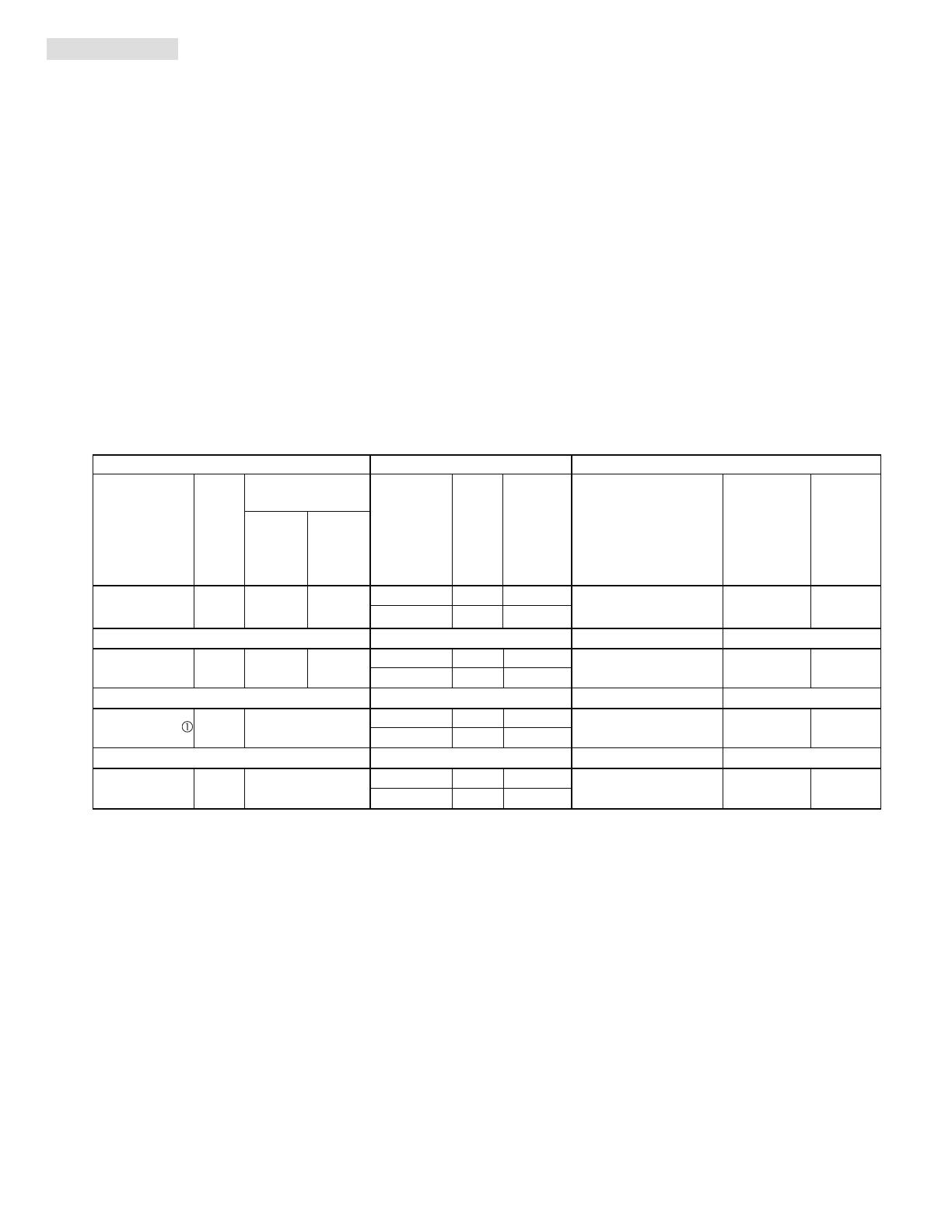
1771 Chassis 1756 Chassis Conversion Mounting Assembly
Cat. No.
Max
Slots
for
I/O
without
Power
Supply
with
Power
Supply
Cat. No.
Max
Slots
for
I/O
Chassis
Width
Cat. No.
Max Slots
for
Conversion
Modules
Chassis
Width
1756-A4
3 10.35
1771-A1B 4 9.01 12.61
1756-A7
6 14.49
1492-MUA1B-A4-A7 4 9.01
1756-A7
6 14.49
1771-A2B 8 14.01 17.61
1756-A10
9 19.02
1492-MUA2B-A7-A10 8 14.01
1756-A10
9 19.02
12 19.01
1756-A13
12 23.15
1492-MUA3-A10-A13 12 19.01
1756-A13
12 23.15
1771-A4B 16 24.01
1756-A17
16 29.06
1492-MUA4-A13-A17 16 24.01
Foot Notes:
1771-A3B is not listed as it is used for 19 inch wide instrumentation panels.
Notice that the 1756 Chassis Width sometimes exceeds the 1771 Chassis Width, with or without the Power Supply. The
Cover-Plate of the 1492 Conversion Mounting Assembly allows the 1756 Chassis to be Left justified, Right justified or
Centered. A complete System Installation Manual ships with the 1492 Conversion Mounting Assembly.
Table 1: Bulletin 1771 to 1756 Chassis Conversion
1771-A3B1
Chassis Width
PN-114287
DIR 10000060098 (Version 01)
Publication 1492-IN045B-EN-E
(3)
IV. Conversion Module Specifications
(Operating specifications are when installed in the Conversion System base / cover-plate assembly)
III. Compatibility
1771
Analog I/O Module
1756
Analog I/O Module
1492
I/O Conversion Module
1492
Cable
1771-IFE (SEC) 1771-IF16 (SEC) 1492-CM1771-LA001 1492-CONACAB005B
1771-IFF (SEC) 1771-IF16 (SEC) 1492-CM1771-LA001 1492-CONACAB005B
1771-IFF (SEV) 1771-IF16 (SEV) 1492-CM1771-LA001 1492-CONACAB005A
1771-IFE (SEV) 1771-IF16 (SEV) 1492-CM1771-LA001 1492-CONACAB005A
Foot Notes:
To understand any issues concerning I/O module compatibility, refer to the Installation Manuals for the specific
1771 and 1756 I/O modules involved.
The 3 numbers indicate the length of the 1492 Cable. Recommended cable lengths of 0.5M are shown.
Additional cable lengths are as follows:
1.0M = 1492-CONACAB010A
1.0M = 1492-CONACAB010B
Specification
Dimensions
11.81 in. (height) x 4.38 in. (depth) x 1.5 in. (width)
300 mm. (height) x 111.25 mm (depth) x 38.1 mm (width)
Storage Temperature -40 to +85°C (-40 to +185°F)
Operating Temperature
0 to 60°C (32 to 140°F)
Operating Humidity
5 to 95% at 60°C (non-condensing)
Shock
Non
-
operating
Operating
50g
30g
Operating Vibration
2g at 10 to 500Hz (Agrees with 1756 I/O module specifications)
Maximum Operating Voltage
30 Vdc
Max. Module Operating Current
Per Point:
Per Module:
2 Amps
12 Amps
Agency Certifications
UL Classified: Under UL File Number E113724
CSA
CE: compliant for all applicable directives
Pollution Degree
2
Environmental Rating IP20
Refer to the Wiring Diagram(s) for
current limits for a specific configuration.
NOTICE
Value
Approximate Shipping Weight
250.6 g (0.55 lbs) (includes carton)
PN-114287
DIR 10000060098 (Version 01)
Publication 1492-IN045B-EN-E
(4)
V. Wiring Diagrams
There are several key application considerations and system specifications (bottom of drawing) when
using these components (conversion module, cable and input module). Read and understand these
considerations before installation.
WARNING
Conversion: 1771-IFE to 1756-IF16 (Single-ended Current)
Conversion Module Installation and Application Considerations
This Bul. 1492 cable consists of a cable wired to one 1756-IF16 RTB. Recommended cable lengths of 0.5M or 1.0M (005=0.5M, 010=1.0M).
See table 2 for other lengths.
SHIELD GROUNDING: In some installations, the field wiring shield was grounded on the 1771 chassis. If this was the case, the installer must
remove these shield connections from the 1771 chassis and they can be connected to the grounding stud on the 1492-CM1771-LA001 module.
The pre-wired cable used between the 1492-CM1771-LA001 module and the 1756-IF16 [1492-CONACAB005B] provides a shield ground lug to
ground the shield at the 1756 ControlLogix chassis, this must be connected. Do NOT connect this ground lug to the conversion module grounding
stud.
This design assumes that all inputs on the1771-IFE were connected to current transmitters. If there was a mix of current and voltage
transmitters, then modification of the pre-wired cable [1492-CONACAB005B] will need to occur at the 1756-IF16 terminal block.
Refer to the 1756-IF16 Installation Manual for modification details.
The 1771-IFE analog input ranges were configured via software, as is the input range for the 1756-IF16. Please ensure the correct input range
is configured in the 1756-IF16.
Refer to your 1771-IFE and 1756-IF16 Installation and User Manuals for additional information concerning comparisons of module wiring,
features and configuration details. [Reference Doc: 41170-944 (Version 02)]
1
6
7
8
9
5
10
15
20
19
21
11
12
13
14
16
17
18
2
3
4
2
IN-0
IN-1
4
IN-2
6
IN-3
8
IN-4
12
IN-5
14
IN-6
16
IN-7
18
RT N
10
RT N
27
RT N
28
IN-9
22
IN-8
20
IN-11
26
IN-10
24
IN-15
36
IN-14
34
Black
RT N
9
White
Red
Green
Orange
Blue
White/Black
Red/Black
Green/Black
Orange/Black
Blue/Black
Black/White
IN-13
32
IN-12
30
Green/White
Blue/White
Black/Red
White/Red
Orange/Red
Blue/Red
Red/Green
Orange/Green
iRTN-1
3
iRTN-0
1
iRTN-3
7
iRTN-2
5
iRTN-7
17
iRTN-6
15
iRTN-5
13
iRTN-4
11
iRTN-9
21
iRTN-8
19
iRTN-11
25
iRTN-10
23
iRTN-15
35
iRTN-14
33
iRTN-13
31
iRTN-12
29
1
2
3
4
5
6
7
8
9
10
11
12
13
14
15
16
17
18
19
20
21
SH
Module Common
Power Supply
Transmitter
2-Wire Transmitter
+
-
Channel 1
Channel 2
Channel 3
Channel 4
Channel 5
Channel 6
Channel 7
Channel 8
Module Common
Module Common
Module Common
Module Common
Channel 9
Channel 10
Channel 11
Channel 12
Channel 13
Channel 14
Channel 15
Channel 16
22
23
24
25
1771-WG Swing Arm
From 1771-IFE
Conversion Module
1492-CM1771-LA001
Cable
1492-CONACAB005B 1756-IF16
PN-114287
DIR 10000060098 (Version 01)
Publication 1492-IN045B-EN-E
(5)
V. Wiring Diagrams (Cont’d)
There are several key application considerations and system specifications (bottom of drawing) when
using these components (conversion module, cable and input module). Read and understand these
considerations before installation.
WARNING
Conversion: 1771-IFE to 1756-IF16 (Single-ended Voltage)
Conversion Module Installation and Application Considerations
This Bul. 1492 cable consists of a cable wired to one 1756-IF16 RTB. Recommended cable lengths of 0.5M or 1.0M (005=0.5M, 010=1.0M).
See table 2 for other lengths.
SHIELD GROUNDING: In some installations, the field wiring shield was grounded on the 1771 chassis. If this was the case, the installer must
remove these shield connections from the 1771 chassis and they can be connected to the grounding stud on the 1492-CM1771-LA001 module.
The pre-wired cable used between the 1492-CM1771-LA001 module and the 1756-IF16 [1492-CONACAB005A] provides a shield ground lug to
ground the shield at the 1756 ControlLogix chassis, this must be connected. Do NOT connect this ground lug to the conversion module grounding
stud.
This design assumes that all inputs on the1771-IFE were connected to current transmitters. If there was a mix of current and voltage
transmitters, then modification of the pre-wired cable [1492-CONACAB005A] will need to occur at the 1756-IF16 terminal block.
Refer to the 1756-IF16 Installation Manual for modification details.
The 1771-IFE analog input ranges were configured via software, as is the input range for the 1756-IF16. Please ensure the correct input range
is configured in the 1756-IF16.
Refer to your 1771-IFE and 1756-IF16 Installation and User Manuals for additional information concerning comparisons of module wiring,
features and configuration details. [Reference Doc: 41170-945 (Version 02)]
1771-WG Swing Arm
From 1771-IFE
Conversion Module
1492-CM1771-LA001
Cable
1492-CONACAB005A 1756-IF16
Power Supply
Transmitter
3-Wire Transmitter
1
6
7
8
9
5
10
15
20
19
21
11
12
13
14
16
17
18
2
3
4
Black
White
Red
Green
Orange
Blue
White/Black
Red/Black
Green/Black
Orange/Black
Blue/Black
Black/White
Green/White
Blue/White
Black/Red
White/Red
Orange/Red
Blue/Red
Red/Green
Orange/Green
1
2
3
4
5
6
7
8
9
10
11
12
13
14
15
16
17
18
19
20
21
SH
Module Common
Channel 1
Channel 2
Channel 3
Channel 4
Channel 5
Channel 6
Channel 7
Channel 8
Module Common
Module Common
Module Common
Module Common
Channel 9
Channel 10
Channel 11
Channel 12
Channel 13
Channel 14
Channel 15
Channel 16
22
23
24
25
+
-
2
IN-0
IN-1
4
IN-2
6
IN-3
8
IN-4
12
IN-5
14
IN-6
16
IN-7
18
RTN
10
RTN
27
RTN
28
IN-9
22
IN-8
20
IN-11
26
IN-10
24
IN-15
36
IN-14
34
RTN
9
IN-13
32
IN-12
30
PN-114287
DIR 10000060098 (Version 01)
Publication 1492-IN045B-EN-E
(6)
V. Wiring Diagrams
There are several key application considerations and system specifications (bottom of drawing) when
using these components (conversion module, cable and input module). Read and understand these
considerations before installation.
WARNING
Conversion: 1771-IFF to 1756-IF16 (Single-ended Current)
1
6
7
8
9
5
10
15
20
19
21
11
12
13
14
16
17
18
2
3
4
2
IN-0
IN-1
4
IN-2
6
IN-3
8
IN-4
12
IN-5
14
IN-6
16
IN-7
18
RTN
10
RTN
27
RTN
28
IN-9
22
IN-8
20
IN-11
26
IN-10
24
IN-15
36
IN-14
34
Black
RTN
9
White
Red
Green
Orange
Blue
White/Black
Red/Black
Green/Black
Orange/Black
Blue/Black
Black/White
IN-13
32
IN-12
30
Green/White
Blue/White
Black/Red
White/Red
Orange/Red
Blue/Red
Red/Green
Orange/Green
iRTN-1
3
iRTN-0
1
iRTN-3
7
iRTN-2
5
iRTN-7
17
iRTN-6
15
iRTN-5
13
iRTN-4
11
iRTN-9
21
iRTN-8
19
iRTN-11
25
iRTN-10
23
iRTN-15
35
iRTN-14
33
iRTN-13
31
iRTN-12
29
1
2
3
4
5
6
7
8
9
10
11
12
13
14
15
16
17
18
19
20
21
SH
Module Common
Transmitter
Power Supply
+
2-Wire Transmitter
-
Channel 1
Channel 2
Channel 3
Channel 4
Channel 5
Channel 6
Channel 7
Channel 8
Module Common
Module Common
Module Common
Module Common
Channel 9
Channel 10
Channel 11
Channel 12
Channel 13
Channel 14
Channel 15
Channel 16
22
23
24
25
Conversion Module Installation and Application Considerations
This Bul. 1492 cable consists of a cable wired to one 1756-IF16 RTB. Recommended cable lengths of 0.5M or 1.0M (005=0.5M, 010=1.0M).
See table 2 for other lengths.
SHIELD GROUNDING: In some installations, the field wiring shield was grounded on the 1771 chassis. If this was the case, the installer must
remove these shield connections from the 1771 chassis and they can be connected to the grounding stud on the 1492-CM1771-LA001 module.
The pre-wired cable used between the 1492-CM1771-LA001 module and the 1756-IF16 [1492-CONACAB005B] provides a shield ground lug to
ground the shield at the 1756 ControlLogix chassis, this must be connected. Do NOT connect this ground lug to the conversion module grounding
stud.
This design assumes that all inputs on the 1771-IFF were connected to current transmitters. If there was a mix of current and voltage
transmitters, then modification of the pre-wired cable [1492-CONACAB005B] will need to occur at the 1756-IF16 terminal block. Refer to the
1756-IF16 Installation Manual for modification details.
The 1771-IFF analog input ranges were configured via software, as is the input range for the 1756-IF16. Please ensure the correct input range
is configured in the 1756-IF16.
Refer to your 1771-IFF and 1756-IF16 Installation and User Manuals for additional information concerning comparisons of module wiring,
features and configuration details. [Reference Doc: 41171-023 (Version 00)]
1771-WG Swing Arm
From 1771-IFF
Conversion Module
1492-CM1771-LA001
Cable
1492-CONACAB005B 1756-IF16
PN-114287
DIR 10000060098 (Version 01)
Publication 1492-IN045B-EN-E
(7)
V. Wiring Diagrams (Cont’d)
There are several key application considerations and system specifications (bottom of drawing) when
using these components (conversion module, cable and input module). Read and understand these
considerations before installation.
WARNING
Conversion: 1771-IFF to 1756-IF16 (Single-ended Voltage)
Conversion Module Installation and Application Considerations
This Bul. 1492 cable consists of a cable wired to one 1756-IF16 RTB. Recommended cable lengths of 0.5M or 1.0M (005=0.5M, 010=1.0M).
See table 2 for other lengths.
SHIELD GROUNDING: In some installations, the field wiring shield was grounded on the 1771 chassis. If this was the case, the installer must
remove these shield connections from the 1771 chassis and they can be connected to the grounding stud on the 1492-CM1771-LA001 module.
The pre-wired cable used between the 1492-CM1771-LA001 module and the 1756-IF16 [1492-CONACAB005A] provides a shield ground lug to
ground the shield at the 1756 ControlLogix chassis, this must be connected. Do NOT connect this ground lug to the conversion module grounding
stud.
This design assumes that all inputs on the1771-IFF were connected to voltage transmitters. If there was a mix of current and voltage
transmitters, then modification of the pre-wired cable [1492-CONACAB005A] will need to occur at the 1756-IF16 terminal block. Refer to the
1756-IF16 Installation Manual for modification details.
The 1771-IFF analog input ranges were configured via software, as is the input range for the 1756-IF16. Please ensure the correct input range
is configured in the 1756-IF16.
Refer to your 1771-IFF and 1756-IF16 Installation and User Manuals for additional information concerning comparisons of module wiring,
features and configuration details. [Reference Doc: 41171-024 (Version 00)]
1771-WG Swing Arm
From 1771-IFF
Conversion Module
1492-CM1771-LA001
Cable
1492-CONACAB005A 1756-IF16
PN-114287
DIR 10000060098 (Version 01)
Publication 1492-IN045B-EN-E
1
6
7
8
9
5
10
15
20
19
21
11
12
13
14
16
17
18
2
3
4
Black
White
Red
Green
Orange
Blue
White/Black
Red/Black
Green/Black
Orange/Black
Blue/Black
Black/White
Green/White
Blue/White
Black/Red
White/Red
Orange/Red
Blue/Red
Red/Green
Orange/Green
1
2
3
4
5
6
7
8
9
10
11
12
13
14
15
16
17
18
19
20
21
SH
Module Common
Channel 1
Channel 2
Channel 3
Channel 4
Channel 5
Channel 6
Channel 7
Channel 8
Module Common
Module Common
Module Common
Module Common
Channel 9
Channel 10
Channel 11
Channel 12
Channel 13
Channel 14
Channel 15
Channel 16
22
23
24
25
Transmitter
Power Supply
+
-
3-Wire Transmitter
2
IN-0
IN-1
4
IN-2
6
IN-3
8
IN-4
12
IN-5
14
IN-6
16
IN-7
18
RTN
10
RTN
27
RTN
28
IN-9
22
IN-8
20
IN-11
26
IN-10
24
IN-15
36
IN-14
34
RTN
9
IN-13
32
IN-12
30
PN-114287
DIR 10000060098 (Version 01)
Publication 1492-IN045B-EN-E
Printed in U.S.A.
  • Page 1 1
  • Page 2 2
  • Page 3 3
  • Page 4 4
  • Page 5 5
  • Page 6 6
  • Page 7 7
  • Page 8 8

Allen-Bradley 1756 ControlLogix User manual

Type
User manual
This manual is also suitable for

Allen-Bradley 1756 ControlLogix is a powerful automation controller designed for a wide range of industrial applications. With its modular design, the 1756 ControlLogix offers flexibility and scalability, allowing users to customize their control system to meet specific requirements. Some key capabilities of the 1756 ControlLogix include:

  • High-performance processing: The 1756 ControlLogix features a powerful processor that enables fast execution of control programs, ensuring efficient and reliable operation.

  • Extensive I/O capabilities: The 1756 ControlLogix supports a wide range of I/O modules, providing flexibility for connecting to various sensors, actuators, and other devices.

Ask a question and I''ll find the answer in the document

Finding information in a document is now easier with AI