Page is loading ...

1
© Copyright 2020 Printed
Before You Start
General Information
Your Third Function Valve Kit is exclusively designed for
your Kubota B2301 and B2601 tractors. Please read
these installation instructions thoroughly before
assembling this kit to your Kubota tractor and loader.
These assembly instructions apply to the Third Function
Valve Kit listed below:
• 380-354A: 3FVK FF B2601 . . . . . . . . . . . . . . . . page 3
Further Assistance
Your Land Pride dealer wants you to be satisfied with
your new Third Function Valve Kit. If for any reason you
do not understand any part of this manual or are not
satisfied with the service received, the following actions
are suggested:
1. Discuss any problems you have with your Third
Function Valve Kit with your dealership service
personnel so they can address the problem.
2. If you are still not satisfied, seek out the owner or
general manager of the dealership, explain the
question/problem, and request assistance.
3. For further assistance write to:
Land Pride Service Department
1525 East North Street
P.O. Box 5060
Salina, Ks. 67402-5060
E-mail address
lpservicedept@landpride.com
When you see this symbol, the subsequent
instructions and warnings are serious - follow
without exception. Your life and the lives of others
depend on it!
!
WARNING: Cancer and reproductive harm.
www.P65Warnings.ca.gov
!
California Proposition 65
IMPORTANT: Before you begin, thoroughly read
these instructions and check to be sure all parts are
accounted for. Please retain these installation
instructions for future reference and parts ordering
information.
Assembly Instructions
A detailed listing of parts for this kit is provided on page 8
for kits. Use the list that is for your specific Third Function
Valve Kit as a checklist to inventory parts received.
Please contact your local Land Pride dealer for any
missing hardware.
Direction Reference
All directional references are made from the operator
seat while facing the direction the machine will operate.
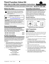
Directional Arrows Used in Illustrations
Initial Preparations
WARNING
!
To avoid serious injury or death: Hydraulic fluid under high
pressure can penetrate the skin and/or eyes causing a serious
injury. Wear protective gloves and safety glasses or goggles
when working with hydraulic systems.
The steps listed below must be followed before installing
this kit:
1. If the front loader is not attached to the tractor, skip to
step 8. Otherwise, continue with step 2 below.
2. Lower loader arms fully down, turn tractor off, and
relieve all hydraulic pressure to the front loader
couplers by operating the loader control lever(s) in all
directions.
3. Having released all hydraulic pressure, lock the
control lever(s) from moving.
4. Remove all mechanical connections securing the
front loader to the tractor.
5. Disconnect all hydraulic lines from the front loader.
6. Refer to your tractor/loader Operator’s Manual for
additional unhooking instructions.
7. Restart tractor and slowly back away from the loader.
8. Park tractor on a flat, level surface. Put tractor in park
or set park brake, turn off engine, and remove switch
key to prevent unauthorized starting.
9. Place chocks in front and back of the tractor’s left rear
wheel.
10. As a safety precaution, disconnect the battery cable
from the battery’s negative (-) terminal. Move
negative cable away from the terminal to avoid
accidental contact.
U
D
B
F
R
L
U = up
L = left
B = back
D = down
R = right
F = front
KEY:
For B2301 and B2601 Kubota Tractors with LA434 Loader
Third Function Valve Kit
#380-354A Installation Instructions
Manual No. 380-353M
8/20/20

Assembly Instructions
2
Third Function Valve Kit #380-354A Installation Instructions Manual No. 380-353M 8/20/20
Install Hydraulic Hoses (#6 & #7)
Refer to Figure 3 on page 3:
1. Locate power beyond port on the right side of the
tractor where steel tube in step 6 was removed. Screw
the large hydraulic straight adapter (#2) into the
power beyond port until tight.
2. Screw 90
o
elbow (#3) to adapter (#2). Do not tighten
at this time.
3. Screw the 48" long hose (#7) to 90
o
elbow (#3). Do
not tighten hose at this time.
4. Locate return to tank port under the tractor seat
where steel tube in step 6 was removed. Determine
which fitting, elbow (#4) or straight adapter (#5), when
installed in this port will align best with hose (#6).
Screw this fitting into the tank port. Do not tighten
fitting at this time.
5. Screw 60" long hydraulic hose (#6) to fitting (#4 or
#5). Do not tighten at this time.
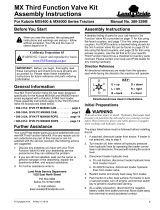
Valve Location
Figure 2
6. Refer to Figure 2: Route hydraulic hoses (#6 & #7)
under the tractor platform to loader mount (A) on the
right side of the tractor.
NOTE: Depending on the tractor model and/or
options, the seat support frame may need to be
removed to performing the following steps.
NOTE: Depending on the tractor model, either the
90
o
elbow (#4) or straight adapter (#5) will align best
between return to tank port and hose (#6).
98 11
17
13
12
16
6
7
74492
18A
14B
14A
18B
20
A
10T
10P
Remove Power Beyond Steel Tube
Figure 1
Remove Existing Steel Tube
Refer to Figure 1:
1. Verify the tractor’s left rear wheel has been chocked
in-front and in-back of the wheel.
2. Loosen lug nuts on the right rear wheel. Do not
remove lug nuts at this time.
3. Jack right rear wheel off the ground and place a jack
stand under the right rear axle.
4. Lower right rear axle onto a jack stand. The rear
wheel should be slightly off the ground. Make sure the
jack stand is secured and will not slip out from under
the tractor axle.
5. Remove right rear wheel lug nuts and the right rear
wheel.
6. Locate and remove the steel tube that connects
between the power beyond port located on the right
side of the tractor and return to tank port located
under the tractor seat and just in front of the rear seat
mount.
74519
Power Beyond Port
Return to Tank Port
Rear Seat Mount
Front Seat Mount
Steel Tube
IMPORTANT: Land Pride recommends that your
dealer remove the steel tube and connect hydraulic
hoses to your tractor’s power beyond port and return
to tank port. Improper hook-up could cause damage
to your tractor and/or Third Function Valve.
Assembly Instructions

Assembly Instructions
8/20/20 Third Function Valve Kit #380-354A Installation Instructions Manual No. 380-353M
3
Install Valve
Refer to Figure 2 on page 2 & Figure 3:
1. Install valve (#12) to bracket (#17) with 1/4"-20 x 7/8"
hex socket bolts (#16). Tighten bolts to the correct
torque.
2. Attach adapters (#13) to ports “A” & “B” in valve (#12)
and tighten.
3. Install dust caps (#15) over adapters (#13).
4. Attach male couplers (#14) to adapters (#13) and
tighten.
5. Attach elbows (#10) to ports "T" & "P" in valve (#12).
Do not tighten elbows at this time.
Refer to Figure 2 on page 2:
6. Attach mount (#17) to existing holes in front loader
mount (A) using 3/8"-16 x 1 1/2" bolts (#8), flat
washers (#9), and flange lock nuts (#11). Tighten
flange lock nuts to the correct torque.
7. Attach 62" long hose (#6) to elbow (#10T) in port “T”.
Do not tighten hose to the elbow at this time.
8. Attach 48" long hose (#7) to elbow (#10P) in port “P”.
Do not tighten hose to the elbow at this time.
Refer to Figure 3:
9. Tighten elbows (#10) to valve (#12).
10. Tighten hoses (#6 & #7) to elbows (#10).
11. Tighten elbow fitting (#3) to straight adapter (#2).
12. Tighten hose (#7) to elbow (#3).
13. Tighten fitting (#4 or #5) to tank port.
14. Tighten hose (#6) to fitting (#4 or #5).
15. Secure hoses (#6 & #7) as needed to the underside
of the tractor with cable ties (#28).
Prepare Tractor for Operation
1. Install right rear wheel and snug-up wheel lug nuts.
2. Jack axle up and remove jack stand.
3. Lower tractor down and tighten rear wheel lug nuts in
a crisscross pattern. Refer to tractor Operator's
Manual for proper torque value.
4. Remove chocks.
5. Check tractor hydraulic fluid level. If low, add
recommended hydraulic fluid. Refer to your tractor
Operator's Manual for recommended hydraulic fluid
and procedure for checking hydraulic fluid level.
Third Function Valve Kit
Figure 3
U
D
R
L
F
B
74485
Attaches to the positive (+) post on the tractor battery.
Port “A”
Port “B”
Port “T”
VALVE PORT IDENTIFICATION
Port “P”

Assembly Instructions
4
Third Function Valve Kit #380-354A Installation Instructions Manual No. 380-353M 8/20/20
Control Lever Assembly
Refer to Figure 3 on page 3 & Figure 4:
1. Remove existing knob (not shown) from end of
control lever “D”.
2. Install new control handle (#1) onto control lever (D).
Adjust control handle (#1) to align the push buttons to
suit the operator and then tighten set screws (#1A).
Tighten jam nuts (#1B) to lock set screws.
3. Thread control handle wiring harness (#1C) through
hole “E” and forward under the tractor platform.
4. Secure wire harness (#1C) with cable ties (#28)
along control lever (D) as needed.
Refer to Figure 5:
5. Reference Connections (#1E):
a. Connect one black wire in wire harness (#1C) to
the black wire in harness (#12A).
b. Connect the other black wire in harness (#1C) to
the white wire in harness (#12A).
6. Reference Connection (#1D):
a. Connect the two red wires in wire harness (#1C)
to one end of the fused red wire harness (#29).
b. Connect opposite end of wire harness (#29) to the
positive (+) post on the tractor battery.
7. Secure wire harness (#1C, #29, & #12A) with cable
ties (#28) as needed.
8. Reconnect the disconnected battery cable in step 10
on page 1 to the battery’s negative (-) terminal.
NOTE:
Wire harness (#1C) is attached to control knob (#1).
Wire harness (#12A) is attached to valve (#12).
Wire harness (#29) includes fuse (#30) and attaches
to the tractor battery.
Control Stick Assembly
Figure 4
Bulkhead Mount with Flat Faced Couplers
Figure 5
1
1A 1B
D
E
1C
Push Buttons
74502
28
1C
74503
Attaches to the positive (+)
post on the tractor battery.

Assembly Instructions
8/20/20 Third Function Valve Kit #380-354A Installation Instructions Manual No. 380-353M
5
Cross Beam & Hose Holder Assembly
Figure 6
Bulkhead Mount Assembly
Refer to Figure 3 on page 3, Figure 6, & Figure 7:
1. Orient as shown and attach bulk head mount (#27) to
the right-hand side of loader crossbeam “F". Secure
mount with u-bolt (#26) and hex whiz nuts (#21).
Tighten hex whiz nuts to the correct torque.
2. Remove jam nuts on bulkhead adapters (#22). Insert
bulkheads through holes (A & B) in mount (#27) and
secure with removed jam nuts. Tighten jam nuts.
3. Attach adapters (#23) to the bulkhead fittings (#22).
4. Attach male coupler (#24) to adapter (#23) in line
with hole (A). Tighten coupler to the adapter.
5. Attach female coupler (#25) to adapter (#23) in line
with hole (B). Tighten coupler to the adapter.
6. Attach 72" long hydraulic hoses (#20) to bulkhead
adapters (#22).
Refer to Figure 3 on page 3 & Figure 8:
7. Install female couplers (#18) and black dust
plugs (#19) to hydraulic hoses (#20).
8. Route hydraulic hoses (#20) along the loader arm
and through loader hose loop bracket “G” to the third
function valve assembly (#12).
9. Connect quick coupler (#18A) to quick
coupler (#14A), port “A” on valve block (#12).
10. Connect quick coupler (#18B) to quick
coupler (#14B), port “B” on valve block (#12).
11. Secure hydraulic hoses (#24) as needed with
cable ties (#5).
27
21
25
24
22
26
23
20
74534
F
NOTE: Quick couplers (#18A & #14A) are in line
with male coupler (#24). Quick couplers
(#18B & #14B) are in line with female coupler (#25).
Bulkhead Mount with Flat Faced Couplers
Figure 7
Hose Route Along Loader Arm
Figure 8
73126
21
22
23
24
25
26
27
A
B
G
37030
20
20

Assembly Instructions
6
Third Function Valve Kit #380-354A Installation Instructions Manual No. 380-353M 8/20/20
Check Operation and Fluid Level
The Third Function Valve is now ready to be used with a
multitude of attachments. Be sure to familiarize yourself
with a complete understanding of how to operate the
Third Function Valve Kit.
DANGER
!
To avoid serious injury or death:
Do not allow bystanders to be near the attachment, loader
arms, or tractor during operation. They can become
entangled, pinched, or crushed by the equipment. Disconnect
and lockout power source before making adjustments or
servicing tractor and attachment.
1. Hook attachment to the tractor front loader and
couple hydraulic hoses to the bulkhead couplers at
the front of the loader.
2. Raise attachment off the ground and operate the third
function hydraulics using the push-buttons on the
newly installed control handle.
• The top red button switch will actuate the
attachment in one direction.
• The bottom red button switch will actuate the
attachment in the opposite direction.
3. Switch couplers on the attachment’s hydraulic hoses
if the hydraulic cylinder(s) operate in the opposite
direction intended.
4. Once hoses and cylinder(s) are full of hydraulic fluid,
check tractor hydraulic fluid level.
5. If low, add recommended hydraulic fluid.
IMPORTANT: Refer to your tractor Operator’s
Manual for recommended hydraulic fluid and
procedure for checking hydraulic fluid level.
Relieve Hydraulic System Pressure
Be sure to lower the attachment to the ground and to
relieve all hydraulic pressure to the attachment before
leaving the tractor seat. Relieve hydraulic pressure to the
attachment as follows:
1. Turn tractor switch key to off.
2. Press and hold both red buttons down on the control
handle until all movement at the attachment stops.

Assembly Instructions
8/20/20 Third Function Valve Kit #380-354A Installation Instructions Manual No. 380-353M
7
Control Handle
Figure 9
380-165S Push Button Control Handle
Refer to Figure 9:
Item Part No. Description Qty
1 801-091C CRPHMS 6-32X5/8 SS . . . . . . . . . . . . . . . . . . . . . . . . . . . . . . . . . . . . . . . . . . . . . . . . . . . . 3
2 837-053C COVER, PUSH BUTTON CNTRL HNDL. . . . . . . . . . . . . . . . . . . . . . . . . . . . . . . . . . . . . . . 1
3 837-054C BASE, PUSH BUTTON CNTRL HNDL . . . . . . . . . . . . . . . . . . . . . . . . . . . . . . . . . . . . . . . . 1
4 833-739C SWITCH, P9 PB NO SPST MOM RED . . . . . . . . . . . . . . . . . . . . . . . . . . . . . . . . . . . . . . . . 2
5 804-054C WASHER LOCK #10 . . . . . . . . . . . . . . . . . . . . . . . . . . . . . . . . . . . . . . . . . . . . . . . . . . . . . . 1
6 801-250C HSBHCS #10-32X1 3/8. . . . . . . . . . . . . . . . . . . . . . . . . . . . . . . . . . . . . . . . . . . . . . . . . . . . 1
7 803-008C NUT HEX 5/16-18 PLT . . . . . . . . . . . . . . . . . . . . . . . . . . . . . . . . . . . . . . . . . . . . . . . . . . . . 2
8 801-204C SCREW SET SCKT HD 5/16-18X3/4 . . . . . . . . . . . . . . . . . . . . . . . . . . . . . . . . . . . . . . . . . 2
9 380-225D MOUNT TUBE, CONTROL STICK . . . . . . . . . . . . . . . . . . . . . . . . . . . . . . . . . . . . . . . . . . . 1
10 803-269C NUT HEX 10-32 PLT . . . . . . . . . . . . . . . . . . . . . . . . . . . . . . . . . . . . . . . . . . . . . . . . . . . . . . 1
73015

Assembly Instructions
8
Third Function Valve Kit #380-354A Installation Instructions Manual No. 380-353M 8/20/20
Third Function Valve Kit
Figure 10
74485
851-350C - (#20)
811-253C - (#6)
841-563C - (#7)
Hydraulic Hose Identification Chart
73128
VALVE PORT IDENTIFICATION
Attaches to the positive (+) post on the tractor battery.
Port “A”
Port “B”
Port “T”
Port “P”

Assembly Instructions
8/20/20 Third Function Valve Kit #380-354A Installation Instructions Manual No. 380-353M
9
Kit No. 380-354A THIRD FUNCTION VALVE KIT (Equipped with flat faced couplers)
Refer to Figure 10 on page 8:
Item Part No. Description Qty
1 380-165S ASY, PUSH BUTTON CNTRL HNDL (See page 7 for component breakdown). . . . . . . . . . 1
2 811-133C AD 9/16MJIC 3/4MORB . . . . . . . . . . . . . . . . . . . . . . . . . . . . . . . . . . . . . . . . . . . . . . . . . . . 1
3 811-169C EL 9/16MJIC 9/16FJIC . . . . . . . . . . . . . . . . . . . . . . . . . . . . . . . . . . . . . . . . . . . . . . . . . . . . 1
4 871-106C AD BANJO 3/8 MBSPP - 9/16 MJIC . . . . . . . . . . . . . . . . . . . . . . . . . . . . . . . . . . . . . . . . . . 1
5 811-253C HH3/8R2 062 9/16FJIC . . . . . . . . . . . . . . . . . . . . . . . . . . . . . . . . . . . . . . . . . . . . . . . . . . . . 1
6 841-563C HH3/8R2 048 9/16FJIC . . . . . . . . . . . . . . . . . . . . . . . . . . . . . . . . . . . . . . . . . . . . . . . . . . . . 1
7 802-022C HHC 3/8-16X 1 1/2 GR5 . . . . . . . . . . . . . . . . . . . . . . . . . . . . . . . . . . . . . . . . . . . . . . . . . . . 2
8 804-012C WASHER FLAT 3/8 SAE PLT . . . . . . . . . . . . . . . . . . . . . . . . . . . . . . . . . . . . . . . . . . . . . . . 2
9 811-416C EL 45 9/16MJIC 9/16MORB . . . . . . . . . . . . . . . . . . . . . . . . . . . . . . . . . . . . . . . . . . . . . . . . 2
10 803-209C NUT FLANGE LOCK 3/8-16 PLT . . . . . . . . . . . . . . . . . . . . . . . . . . . . . . . . . . . . . . . . . . . . 2
11 810-926C VALVE, THIRD FUNCTION . . . . . . . . . . . . . . . . . . . . . . . . . . . . . . . . . . . . . . . . . . . . . . . . 1
12 811-636C AD 9/16MORB STRAIGHT UNION. . . . . . . . . . . . . . . . . . . . . . . . . . . . . . . . . . . . . . . . . . . 2
13 841-467C CP 9/16 FORB QD 1/4 BODY MALE . . . . . . . . . . . . . . . . . . . . . . . . . . . . . . . . . . . . . . . . . 2
14 851-976C DUST CAP, 1/4" QD AG . . . . . . . . . . . . . . . . . . . . . . . . . . . . . . . . . . . . . . . . . . . . . . . . . . . 2
15 802-418C HSHCS 1/4-20X7/8 . . . . . . . . . . . . . . . . . . . . . . . . . . . . . . . . . . . . . . . . . . . . . . . . . . . . . . 2
16 380-256C BRKT, VALVE MOUNT . . . . . . . . . . . . . . . . . . . . . . . . . . . . . . . . . . . . . . . . . . . . . . . . . . . . 1
17 841-466C CP 9/16FORB QD 1/4BODY FEMALE . . . . . . . . . . . . . . . . . . . . . . . . . . . . . . . . . . . . . . . . 2
18 851-977C DUST PLUG, 1/4" QD AG . . . . . . . . . . . . . . . . . . . . . . . . . . . . . . . . . . . . . . . . . . . . . . . . . 2
19 851-350C HH1/4R2 072 9/16MORB 9/16FJIC. . . . . . . . . . . . . . . . . . . . . . . . . . . . . . . . . . . . . . . . . . . 2
20 803-198C NUT HEX WHIZ 3/8-16 PLT . . . . . . . . . . . . . . . . . . . . . . . . . . . . . . . . . . . . . . . . . . . . . . . . 2
21 851-276C AD 9/16MJIC9/16MORB BLKHD W/LN . . . . . . . . . . . . . . . . . . . . . . . . . . . . . . . . . . . . . . . 2
22 841-103C AD 3/4MORB 9/16FORB . . . . . . . . . . . . . . . . . . . . . . . . . . . . . . . . . . . . . . . . . . . . . . . . . . 2
23 841-099C CP 3/4FORB QD FLATFACE . . . . . . . . . . . . . . . . . . . . . . . . . . . . . . . . . . . . . . . . . . . . . . . 1
24 861-543C CP 3/4FORB QD FML FLATFACE . . . . . . . . . . . . . . . . . . . . . . . . . . . . . . . . . . . . . . . . . . . 1
25 806-261C U-BOLT 3/8-16X3X3 5/8 RND . . . . . . . . . . . . . . . . . . . . . . . . . . . . . . . . . . . . . . . . . . . . . . 1
26 380-223D PLATE, BX BLKHD MOUNT. . . . . . . . . . . . . . . . . . . . . . . . . . . . . . . . . . . . . . . . . . . . . . . . 1
27 800-112C CABLE TIE .19X7.25 1.75D 50LB . . . . . . . . . . . . . . . . . . . . . . . . . . . . . . . . . . . . . . . . . . . . 8
28 833-650C BLADE FUSE HOLDER, MINI . . . . . . . . . . . . . . . . . . . . . . . . . . . . . . . . . . . . . . . . . . . . . . 1
29 833-495C FUSE, 10 AMP MINI BLADE . . . . . . . . . . . . . . . . . . . . . . . . . . . . . . . . . . . . . . . . . . . . . . . 1

Corporate Office: P.O. Box 5060
Salina, Kansas 67402-5060 USA
www.landpride.com
/