2
Third Function Valve Kit #380-166A Installation Instructions 380-167M 4/10/17
Assembly Instructions
?
Connect Hydraulic Hoses to Power
Beyond Ports (With Backhoe)
1. Locate and remove hydraulic hose that connects
power beyond port of tractor’s loader valve assembly
to outlet block under the tractor platform.
Refer to Figure 2 on page 1:
2. Connect hydraulic hose (#16) from “P” port in third
function valve (#10) to the fitting in outlet block where
hydraulic line was removed in step #1 above.
3. Connect hydraulic hose (#18) from “T” port in
third function valve (#10) to the fitting in the power
port of loader valve where hydraulic hose was
removed in step (#1) above.
4. Secure hoses (#16 & #18) to tractor as needed with
cable ties (#3).
5. Check tractor hydraulic fluid level. If low, add
recommended hydraulic fluid. Refer to your tractor
Operator's Manual for recommended hydraulic fluid
and procedure for checking hydraulic fluid level.
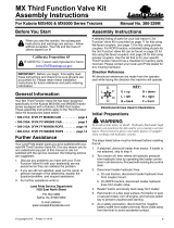
Control Lever Assembly
Refer to Figure 2 on page 1 & Figure 3:
1. Remove existing knob (not shown) from end of
control lever “C”.
2. Install new joystick (#12) over end of control lever “C”
with push buttons facing operator as shown.
3. Tighten set screws (#4) against control lever “C”.
Tighten jam nuts (#7) to secure set screws (#4).
Refer to Figure 2 on page 1:
4. Reference Connections “A”: Connect one
black wire in harness (#13) to one black wire in
harness (#10) and the other black wire in
harness (#13) to one white wire in harness (#10).
5. Reference Connection “B”: Connect the two red
wires in harness (#13) to one end of wire (#15) with
fuse holder (#14), and connect opposite end of
wire (#15) to the positive (+) post on the battery.
Refer to Figure 3:
6. Secure wiring with cable ties (#3) as needed.
Cross Beam Mount Assembly
Refer to Figure 2 on page 1 & Figure 4:
1. Remove existing top and top rear hardware (#5 & #6)
from the right-hand side of loader cross tube “D”.
IMPORTANT: Land Pride recommends that your
dealer connect hydraulic hoses (#16 & #18) to your
tractor’s power beyond ports. Improper hook-up
could cause damage to your tractor.
IMPORTANT: If tractor is equipped with a backhoe,
hydraulic hose #18 should be moved to “P” port in
the third function valve and hydraulic hose (#16)
should be moved to “T” port in the third function
valve.
Figure 3
Figure 4
Figure 5
2. Orient as shown and attach bulk head mount (#2) to
the right-hand side of loader cross tube “D” with a
new W8-1.25 x 30 bolt (#5) and new W8-1.25 x 35
bolt (#6), lock washers (#8) and flat washer (#9).
Tighten bolts (#5 & #6) to the proper torque.
Refer to Figure 2 on page 1, Figure 4, & Figure 5:
3. Route hydraulic hoses (#17) along the loader arm
and through loader loop bracket “E” to the third
function valve assembly (#10).
4. Connect hoses to quick couplers (#11) on
“A” & “B” ports of valve block (#10).
5. Secure hydraulic hoses (#17) as needed with
cable ties (#3).
37119
Push Buttons
13
4
12
C
3
7