Page is loading ...

max 328 Ft
max 360 FT
max 295 Ft
max 262 Ft
max 229 Ft
12 Ft
9 Ft
6 Ft
3 FT
1
%
1
%
1
%
1
%
1
%
1
%
21 Ft
25 Ft
18 Ft
15 Ft
max 197 Ft
1
%
1
%
max 164 Ft
max 131 Ft
6
1
3
7
N F N
2
1
2
K
K
A
A
7a
M
I
H
H
I
2
H
x 2
I
x 2
A
x 1
F
x 1
90 X 110
D
x 4
32 X 55
E
x 2
25 X 40
C
x 1
2" x 1-1/2"
B
K
x 1 x 4
ML
x 2
20 X 32
O
x 1
60 70 80 90 100 110 120 130 140 150
4
5
6
7
8
9
15
20
25
30
Flow rate (liters/min)
0
1
2
0
5
10
15 20 25 30 35 40
Flow rate (gallons/min)
3
Vertical Distance (meters)
Vertical Distance (feet)
5
7b
7c 7d
L
E
E
4
L
E
E
4
L
L
1
Ø 3/4" CPVC (22 mm) Ø 3/4" PVC (28 mm) Ø 1" PVC (32 mm)
G
Closed
Fermé
G
x 2
2" x 2"
J
x 1
1-1/2"
x 1-1/2"
P
x 1
1
D
J
D
N
x 3
50 X 70
D

7 SUITE
13
8
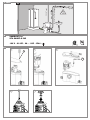
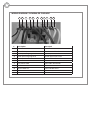
Drain (1/4” per foot gravity fall)
Ø 3/4" or 1" discharge
1-1/2" vent
Max. 25 FT
2%
7e
G
H
SANIBEST
Pro
®
SFA SANIFLO INC
120 V - 60 HZ - 9A - 1 HP - IP44 -
C
B
2c
F
55

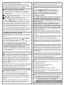
1
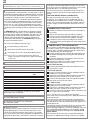
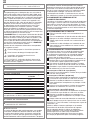
DESCRIPTION
This grinder/pump is manufactured in a factory which is quali-
ty certified to ISO 9001 (2000) accredited by AFAQ. To benefit
from the advantages provided by this new generation system,
it is important to comply with the installation instructions.
The grinder/pump unit is a residential and commercial pum-
ping system for toilet and bathroom fixtures. As shown in fig
n
°
1, it can simultaneously receive wastewater from sanitary
fixtures such as a sink, shower, bathtub but only one toilet
per unit. It is also powerful enough to handle wastewater from
a washing machine through an indirect connection (via utility
sink).
The SANIBEST Pro
®
is designed for the disposal of human
waste, toilet paper and water. It is also capable of handling
occasional sanitary articles flushed down the toilet. They are
not intended to be used for the disposal of kitchen waste
or directly from pump appliances such as a dishwasher.
Installed and used correctly, the SANIBEST Pro
®
will give
consistent and reliable service.
Please note the following warning signs:
« » Possible danger to personnel,
« » Warning of possible electrical hazard,
« » Instructions for use only by qualified professionals,
«WARNING» This is a general warning that failure to
follow instructions could result in poor functioning
of the unit.
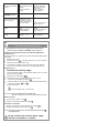
2
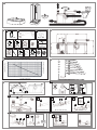
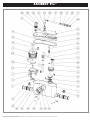
LIST OF ACCESSORIES
3
DIMENSIONS
4
TECHNICAL DATA
Application 1 toilet + shower/bathtub,
sink
Vertical Pumping Max. 25 Ft
Voltage 110-120 V
Frequency 60 Hz
Amperage Max. 9 Amps
Motor 1 HP
Temperature Max. 104° F
Degree of protection IP44
Net Weight 26 lbs
WARNING: Only installations conforming to the above
specifications are acceptable.
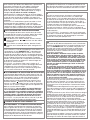
5
PERFORMANCE CURVE
6
VERTICAL/HORIZONTAL PUMPING
COMBINATIONS
7
INSTALLATION
The grinding system must discharge into a minimum 3/4-inch
sanitary drainage pipe. The system will pump up to a maxi-
mum of 25 Ft vertically and then across with a 1/4" per foot
gravity fall (minimum) constantly throughout the horizontal run
to the point of discharge. If you require a vertical lift, it should
precede any horizontal run and should commence as near
as possible to the discharge elbow (no more than 18 inches
away). Once you have started the horizontal run, you cannot
change directions in an upward vertical manner.
The unit has fastenings on the bottom of the casing. This is
meant to secure the pump to the floor and prevent it from
turning.
TANK AND WATER SUPPLY CONNECTION
The tank comes with the fill and flush valve already
assembled. The hardware kit to assembled the tank to
the bowl comes included with the system. Ensure that all
screws, nuts, etc are tightened and well secured. Connect
the water supply hose to the bottom connection of the fill
valve.
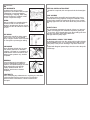
7a
CONNECTION TO THE TOILET
1
- Stretch the flexible sleeve over the entry connection of
the casing
2
- Secure this connection with the cable tie supplied
3
- Push the metal clamp around the flexible sleeve and
then pull the sleeve over the exit spigot of the bowl
4
- Position the metal clamp at the edge of the flexible
sleeve and secure this by tighten the metal clamp with a
screwdriver
7b
CONNECTION OF THE DISCHARGE PIPE
These systems are provided with a discharge elbow which
has a built-in check valve, a flexible discharge hose, a plastic
coupling and a step-down rubber connection. Follow these
steps to connect to your discharge pipe.
1
- Insert the larger end of the plastic discharge elbow into
the rubber discharge hose coming out from the top of
the pump.
2
- Rotate the discharge to any direction and secure the
base of the elbow with a clamp.
3
- Connect the flexible hose to the smaller end of the dis-
charge elbow and secure with a clamp.
For 3/4" CPVC (22 mm)
4
- Insert the discharge pipe inside the flexible hose and
secure with a clamp.
For 3/4" PVC (28 mm)
4
- Insert the smaller end of the plastic coupling inside the
flexible hose ; secure with clamp.
5
- Connect the step-down rubber connection to the other
end of the plastic coupling; secure with a clamp.
6
- Insert the discharge pipe inside the step-down rubber
connection and secure with clamp.
For 1" PVC (32 mm)
4
- Insert the smaller end of the plastic coupling inside the
flexible hose; secure with clamp.
5
- Connect the step-down rubber connection to the other
end of the plastic coupling; secure with a clamp.
6
- Cut off the end of the step-down rubber connection to fit
the 1” pipe; secure with clamp.
NOTE: Use only 3/4” or 1” pipe for the discharge.
Install a ball valve in the discharge line in order to facilitate the
removal of the unit.
If you want for the unit to pump vertically and horizontally,
you may calculate that 3 Ft of vertical lift is equivalent to 30
Ft of horizontal run. Note that all horizontal runs require a 1/4”
per foot gravity fall.
Each bend or change in direction causes minor losses which
must be deducted from the discharge performance (ie.
reduce discharge height by 3 Ft for each 90 degree turn). Use
long sweeping 90 degree elbows or two 45 degree elbows
back-to-back to create the 90 degree turn. Do not use 90
degree elbows.
The connection to the soil stack or sewer pipe should be
made with an approved wye fitting. If you have any doubts
EN
Fully illustrated step by step instructions are
downloadable on www.saniflo.com or www.saniflo.ca

8
ACTIVATING THE UNIT
Once electrical and plumbing connections have been
made, flush the toilet once. The motor should run from
5 to 10 seconds to clear the waste (depending on the
length and height of the pipe run). If it runs for more than
30 seconds, check that the discharge pipe is not kinked
or blocked or check that the non-return valve is correctly
installed.
Flush the toilet checking that all seals, and connections
are watertight. Check both the discharge pipework from
the unit, and the waste pipes from sink or shower.
WARNING: There should be no dripping of water from
the toilet tank or taps. If there is, this will cause the unit
to activate repeatedly as it pumps the water away.
9
USAGE
The normal domain of application of SFA units only
concerns the disposal of human waste, toilet paper and
water. The SANIBEST Pro
®
is a product conceived for
heavier use, suitable for residential or commercial
applications, and can occasionally accept disposal of
sanitary items such as tampons and sanitary pads.
CAUTIONARY NOTES:
Do not discharge any acids, alkaloids, solvents painting,
paint strippers, food waste, plastic bags, metal such as
nails, hairpins, wood, building materials, kitty litter or
anything that could halt or damage or corrode the unit.
Disregarding the above might damage the unit and shall
void your warranty.
Do not hang bleach blocks or hydrochloride cleaners in
the toilet tank. These solutions have been shown to
deteriorate the plastic and neoprene components of the
flush and fill valves, and may cause leaks. In the event of
a power loss do not use the toilet or any other sanitary
fixture connected to the unit since it will not work until
the power is restored.
The toilet works as a conventional flushing toilet and needs
no maintenance in normal use. However, there is nothing
wrong with cleaning out the unit once a year. Do not use
bleach (Be careful not to let water enter the electrical cord
opening).
The unit starts automatically once the toilet is flushed or the
bath, shower, hand basin, etc. discharge and cease opera-
tion once the contents have been pumped away.
Whenever the unit is not in use for long periods of time
(vacation, power failure, maintenance, etc.) turn off the water
supply to the tank and flush the unit to evacuate the water.
No leakage into the bowl should ever be permitted from the
tank.
In areas, which are prone to freezing, the total system must
be properly winterized.This includes the draining of all pipes,
the toilet tank and bowl and the tank. The system is simple
to winterize. Pour a jug of plumbers’ anti-freeze into the tank
and flush the toilet. This will cause the unit to activate and
all remaining water will be replaced by plumber’s anti-freeze.
No parts or labour are warranted when a breakdown occurs
due to freezing.
Ensure that there are no faucets left open. Drops will even-
tually fill up the pump and the resultant repeated start-stop
of the motor may heat up to such an extent, that the thermal
overload switch may eventually operate and automatically
stop the motor, thus possibly causing a flood.
about this section of the installation, please have a plumber
or trade professional install this for you.
Note: If the end of the discharge pipe is lower than the
base of the pump, siphonage can occur. In order to avoid
siphoning on the discharge line, an anti-siphon valve should
be installed at the highest point of the installation.
7c
CONNECTION OF SANITARY FIXTURES
The unit is equipped with two additional 2” inlets, one on
either side of the case. These inlets, which incorporate an
internal check valve, are use to connect the drain pipe from
other sanitary fixtures.
1
- To connect to the side inlets, use the rubber connector
F
or
C
and secure with clamps.
2
- If these inlets are not used, plug the unused inlet with
the plug
G
provided after greasing the joint.
WARNING: Ensure that when connecting a shower or a
bathtub to a SANIBEST Pro
®
, the platform of the shower
or tub would need to be raised a minimum of 8” from the
floor. You may purchase any shower base or tub, as only
the drain pipe connects to the pump. However, a 2" x 8"
platform would need to be built as this would give enough
space for a p-trap and slope toward the side inlets.
NOTE: The actual distance between the p-trap of the sani-
tary fixture and the macerating unit determines the neces-
sary clearance to install the trap and the elevation required
to ensure the minimum gravity flow of 1/4” per foot.
7d
CONNECTION TO A VENT SYSTEM
The grinder/pump unit must be vented. It has two inlets on
the top of the cover: a 1 1/2” port and a hole of smaller dia-
meter.
The unit must be connected to a vent system according to
the plumbing codes. Place the waste inlet
J
(provided) on
the 1 1/2” port and clamp it down. Then,
connect the vent pipe and secure with a clamp. Note that all
fixtures connected to the system must also be vented.
WARNING: Do not use an air admittance valve or a
mechanical spring loaded venting device as these devices
are considered one-way valves. The air pressure inside
and outside the macerating unit must be equal.
A “cheater” vent will obstruct the airflow in one direction.
Note: The smaller diameter 1/2” hole must be plugged with
a plastic cap supplied.
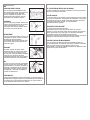
7e
EXAMPLE OF SANIBEST Pro
®
INSTALLATION
7f
CONNECTION TO ELECTRICAL SUPPLY
All wiring should be in accordance with the applicable
electrical code in your territory. The macerating system
requires a single-phase 120-volt, 15 Amp. supply. When
installed in a bathroom, the receptacle should be 40 inches
away (in straight line) from a shower or bathtub. Connect
only to receptacle protected by a ground fault circuit
interrupter (GFCI).
WARNING: risk of electric shock - this pump is suplied with
a grounding conductor and grounding type attachment plug
to reduce the risk of electrical shock. Be certain that it is
connected properly grounded - type receptacle.
10
CARE OF YOUR SANIBEST Pro
®
UNIT
In order to remove scale and clean the macerator and the
bowl, use Saniflo’s descaler.
• Disconnect the power,
• Pour an amount of descalent in the bowl
• Leave it to stand for 1 or 2 hours,
• Re-connect the power,
• Rinse by operating the flushing system twice.
Carry out the operation once every 3 months on average,
but the frequency may need to be changed depending on
the hardness of the water.
11
FAULT FINDING/REMEDIES
For the most part any inconsistencies in the operation
of the unit will be minor and easily rectified. Please refer
to the chart below. If the problem cannot be easily remedied in
this way. Please call our technical support.
Warning - Always disconnect the electricity supply before
attempting any work on the SANIBEST Pro
®

13
REMOVAL
CHANGING THE CONDENSER, MINIATURE CIRCUIT BREAKER, MEMBRANE OR
ELECTRONIC CARD.
If positioning allows, this intervention can be made without taking apart
the large lid.
A
Unplug the machine
B
Unscrew the cover 2c . You will be able to access the condenser,
miniature circuit and electronic card.
C
To change the membrane, disconnect the motor wires from the
electronic card. Then remove the pressure gauge (quarter turn).
REMOVING THE UNIT
Disconnect the electricity supply
Turn off the water supply to the toilet tank. Bail out as much water
from the tank as possible.
D
a) Remove the outlet elbow 21d
E
b) Disconnect the motor wires from the electronic card.
Remove the watertight microband 55 .
F
c) Unclip and lift the cover and disconnect the linking sheath from
the pressure gauge 54 and 55 .
d) Lift out the motor
The hood may be hot – do not touch!
WARNING:
Do not activate the motor when ‘dry’.
(otherwise support washers will be irreparably destroyed)
REMOVAL OF BLADES
G
Unscrew the 3 blade screws 12 .
H
Repair or exchange the blade assembly 5 .
RE-ASSEMBLY OF THE BLADES
I
Before re-assembly, ensure that the drive coupling 61c is
well pressed into the base of the pump
11
.
NOTE: For easy replacement of the lid, lubricate the lid seal 2b
with liquid soap.
Do not reconnect the electrical power supply
until t he re-installation is complete.
All work involving dismantling of the appliance must be
carried out by an approved repair agent
Any replacement of the power supply cable should only be
carried out by an authorized SANIFLO service engineer.
REMEDIES
• Check the appropriate
washers / seals on the
tank / taps etc
• Clean or replace the
non-return valve
• Clean the air vent
• Check the installation
• Call a service engineer to
inspect the motor
• Restore the electrical
supply
• Call a service engineer to
inspect the motor
•
Call a service engineer to
inspect the motor
PROBABLES CAUSES
• The toilet tank or taps are
dripping
• The non-return valve
is faulty
• Venting issue
• The length or height of the
installation is over the
specification, or there are
too many bends/elbows
• The unit is blocked
• The electrical supply is not
active
• Problem with motor or
electrical chamber
• The capacitor 38 or motor is
defective
SYMPTOM
• The motor intermittently
activates
• Motor is surging and water
in the bowl goes down
very slowly
• The motor operates
normally, but continues to
run for a long time
• The motor does not
activate
• The motor hums, but does
not run

14
ADVICE
PIPE SUPPORTS
All sanitary pipe work must be
supported, in accordance with the pipe
manufacturerʼs recommendations.
Avoid dipping or trapping, which may
cause the build up of residual “solids”
and sub- sequent blockage.
BENDS
Where possible long sweeping bends
should be used. Do not use short
elbows. If sweeping 90° elbows are not
available use two 45° elbows to make a
90° turn.
PIPE WORK
All pipe work should be either copper,
PVC or CPVC (Do not use flexible
pipes). Hangers should not be less than
four feet apart to prevent pipe rattling.
DISCHARGE
Never discharge directly into an open
drain, fixture, manhole or rainwater
drainpipe. It is illegal for it constitutes a
health hazard. Direct connections into
sanitary waste systems only, shall be
acceptable.
FREEZING
Ensure all pipe work susceptible to
freezing is adequately insulated or
heated. In unheated buildings, the toilet,
piping and grinding unit must be
properly winterized with “RV or
plumbers” anti-freeze or drained
completely.
ELECTRICITY
Before attempting any maintenance or servicing, the unit must
be disconnected from the power source. The grinding
system must be connected to a Ground Fault Circuit
Interrupter.
VERTICAL INSTALLATION FIRST
If vertical lift is required, this must precede the horizontal pipe
run.
EASY ACCESS
The unit should be accessible and removable in the event
of maintenance being required. During the installation a full-
port ball valve should be installed at the base of any vertical
discharge pipe work from the unit to allow easy service of the
unit.
GRAVITY FALL
The unit accepts wastewater by gravity; it does not “vacuum”
in water. All inlet pipe work must have a positive gravity fall,
(
1
/4" per foot). All horizontal piping from the grinding unit must
also have a positive gravity fall to allow free
drainage when the pump stops.
NO DIAGONAL “UPHILL” PIPE RUNS
All discharge pipe work from the unit should run either directly
vertical upwards from it or in a horizontal plane (with a small
gravity flow) to the point of discharge. Pipe work should not
be
installed with diagonal upward slope from the unit to the point
of discharge.

WIRING DIAGRAM / SCHEMA DE CABLAGE
n° Description Descriptif
1
Green/Yellow motor Vert /Jaune moteur
2
Green/Yellow power cable Vert / Jaune câble alimentation
3
Brown pressure gauge level Marron pressostat niveau
4
Brown pressure gauge level Marron pressostat niveau
5
Brown power cable Marron câble alimentation
6
Brown motor Marron moteur
7
Blue power cable Bleu câble alimentation
8
Blue motor Bleu moteur
9
White condenser Blanc condensateur
10
White motor Blanc moteur
11
White condenseur Blanc condensateur
1 2 3 4 5 6 7 8 9 10 11

LIMITED WARRANTY
2 Year Warranty from Date of Purchase
Subject to the terms and conditions set out below, SFA-SANIFLO INC., (hereafter designated the as the
Company) warrants that it will repair or replace the product or any of its component parts, at the
Company’s discretion if it deems that the product or part it is defective or does not meet the rated
performance due to a maufacturing or material default.
If replacement is to be issued, this will only be extended to the first 180 days starting from the date of
purchase. Warranty repairs will apply after such date up to the warranty’s date of conclusion.
TERMS AND CONDITIONS
The conditions of this warranty are the following:
s The product must be installed in accordance with the use described in the enclosed manuals.
s The product must be connected to a single phase 120V, 60Hz electrical outlet and was not subject
to any negligence, accident or exposure to harmful products or substances..
s The alleged defect or fault must be reported either to the installer or to the Company during the
warranty coverage period.
s The warranty coverage period is valid for 2 years from date of purchase.
PART OR PRODUCT EXCHANGE
The product may be exchange without cost only at the sales outlet where it was purchased subject to
the following conditions:
s4He customer must have an “authorized return number” from the manufacturer in order to validate
exchange.
s4He customer must produce proof of purchase to validate exchange.
LIMITATIONS
1.Fill and flush mechanism are guaranteed as per OEM warranty only.
2.Vitreous china are guaranteed only for a factory defect.
3. Cost of disconnection and reconnection (i.e. labor charges) are not covered by the warranty and are
the end-users responsibility.
4. Cost of mail or freight when a part or parts of the system have to be repaired at the company are
not covered by this warranty.
5. In no event shall the company be liable for any special, incidental or consequential damage, loss, or
injury of whatsoever nature or kind arising from or in connection with the product or any component
thereof.
6. The guarantee is transferable only when the product remains at the same premises as where it was
installed initialy.
Except as set forth in this Limited Warranty, the company disclaims all other warranties, express or
implied, with respect to the product or any component thereof including, but not limited to, all implied
warranties for merchantability and fitness for a particular purpose.
For Service and other inquiries, please call either of the addresses listed below.
United States Canada
SFA-SANIFLO INC.
SFA-SANIFLO INC.
105 Newfield Avenue, Suite A 1-685 Speedvale Avenue West
Edison, NJ 08837 Guelph ON
N1K 1E6
Customer toll free: 800-571-8191 Customer toll free: 800-363-5874 English
Customer toll free: 800-877-8538 French
Telephone: 732-225-6070 Telephone: 519-824-1134
Telefax: 732-225-6072 Telefax: 519-824-1143
Web Site: www.saniflo.com Web Site: www.saniflo.ca
Page is loading ...
Page is loading ...
Page is loading ...
Page is loading ...

WIRING DIAGRAM / SCHEMA DE CABLAGE
n° Description Descriptif
1
Green/Yellow motor Vert /Jaune moteur
2
Green/Yellow power cable Vert / Jaune câble alimentation
3
Brown pressure gauge level Marron pressostat niveau
4
Brown pressure gauge level Marron pressostat niveau
5
Brown power cable Marron câble alimentation
6
Brown motor Marron moteur
7
Blue power cable Bleu câble alimentation
8
Blue motor Bleu moteur
9
White condenser Blanc condensateur
10
White motor Blanc moteur
11
White condenseur Blanc condensateur
1 2 3 4 5 6 7 8 9 10 11
Page is loading ...

SANIBEST Pro
®
© SFA - 04/2012 - D10437 - Graphic Plus +33/1/5399 9605.
WE RESERVE THE RIGHT TO MAKE MODIFICATIONS IN THE FURTHERANCE OF TECHNICAL DEVELOPMENT. SOUS RÉSERVE DE MODIFICATIONS DANS LE BUT D’AMÉLIORER NOS PRODUITS.
-
 1
1
-
 2
2
-
 3
3
-
 4
4
-
 5
5
-
 6
6
-
 7
7
-
 8
8
-
 9
9
-
 10
10
-
 11
11
-
 12
12
-
 13
13
-
 14
14
-
 15
15
-
 16
16


Ask a question and I''ll find the answer in the document
Finding information in a document is now easier with AI
in other languages
- français: Saniflo 013 Manuel utilisateur
Related papers
-
SFA 010 Installation guide
-
 SFA SANIFLO 082.005.083 Installation guide
-
Saniflo 008 Installation guide
-
-
-
-
-
-
SFA SANIACCESS 3 User manual
-

Other documents
-
 SFA-SANIFLO SANISWIFT Installation And Maintenance Instructions Manual
-
 Liberty Pumps ASCENTII-RSW User manual
-
Campingaz Portable Toilet Owner's manual
-
Ryobi RSH-2400R Owner's manual
-
Dometic 8100, 8500, 8600, 8700, 8900 Operating instructions
-
THETFORD 38700 Specification
-
-
-
Coleman Portable Flush Toilet Owner's manual
-
 Star Water Systems S1203 Installation guide


