Page is loading ...

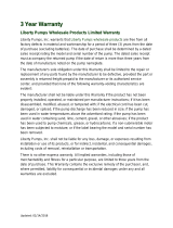
©Copyright 2016 Liberty Pumps Inc. All rights reserved. 1
Installer: Please leave this manual with the
owner/operator for future reference.
Prior to installation, record Model, Serial Number,
and Code Number from pump nameplate for future
reference.
MODEL: _____________________________
SERIAL: _____________________________
INSTALLATION DATE: __________________
7000 Apple Tree Avenue
Bergen, NY 14416
Phone: (800) 543-2550
Fax: (585) 494-1839
www.libertypumps.com
Contents
1.) General Information
2.) Introduction
3.) Installation
4.) Operation
5.) Maintenance
6.) Troubleshooting Chart
7.) Warranty
Installation Manual 5755000F
Models:
Ascent II-ESW
Complete system - elongated toilet
Ascent II-RSW
Complete system – round front toilet
Macerator UPC listed, file 5771;
Toilet UPC listed, file 8056;
Toilet Meets EPA WaterSense Criteria
ASME A112.3.4
CSA B45.9
[Certifications apply to 115V Models Only]

©Copyright 2016 Liberty Pumps Inc. All rights reserved. 2
Before installation, read the following instructions carefully. Each Liberty pump is individually factory tested to ensure
proper performance. Closely following these instructions will eliminate potential operating problems, assuring years of
trouble-free service.
Risk of electric shock. Always disconnect the macerator from the power source before handling or making
adjustments.
These pumps are not to be installed in locations classified as hazardous in accordance with the National Electric
Code, ANSI/NFPA 70.
Qualified personnel should only make the electrical connections and wiring for a pump installation.
This pump is supplied with a grounding-type attachment plug. To reduce the risk of electric shock, be certain that it is
connected to a properly grounded, grounding-type receptacle.
This product must be connected to a ground fault circuit interrupter (GFCI) receptacle or circuit breaker.
Do not bypass grounding wires or remove ground prong from attachment plugs.
Do not use an extension cord.
The installation must be in accordance with the National Electric Code and all applicable local codes and ordinances.
The Macerator has a large opening to accept the discharge hub of a rear discharge toilet. DO NOT place hand or
other objects into this opening even if unit is unplugged. The macerator has razor sharp cutters within this opening.
Decorative covers must be installed for operation, a safety device is integrated into the covers to prevent unintended
operation. The unit may start when energized the first time.
Explosion hazard during installation. PVC cleaners, primers, and cements can release explosive vapors. These
heavier than air vapors can accumulate in the tank. The heat of soldering or sweating copper or other metal pipe can
ignite these vapors causing a violent explosion. If the unit is to be connected to copper discharge or vent piping, all
solvent welded PVC joints must be allowed to cure a minimum of 24 hours. The access cover must be removed to
allow the macerator to be thoroughly ventilated prior to sweating copper pipe near the unit.
Do not use macerator in water over 104 F.
Do not lift macerator by the power cord.
Do not use an air admittance valve or a mechanical spring-
loaded venting device.
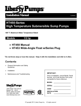
1-1 INSPECTION UPON RECEIPT.
The Ascent II is shipped in 3 separate packages, the toilet tank
(model: Ascent II - TW), toilet bowl (model: Ascent II – RW or EW)
and macerating unit (model: Ascent II - MUW). The shipping
containers should be immediately inspected for damage that may
have occurred in shipment. Exercise care in opening the shipping
container to avoid damage to the contents. Remove any blocking
and packaging from within the containers.
Check all packaging for spare parts before discarding. Visually
check the macerating unit and any spare parts for damage.
Check for damaged electrical wires, especially where they exit the
macerating tank. Report any damage or shortage of parts to
Liberty Pumps 1-800 543-2550.
List of included parts:
Toilet Bowl
Toilet Tank
Macerator
Macerator tank
Rubber couplings with clamps
Reducing bushings
9-volt battery
Allen wrench - 3/16”
Grease packet
1. General Information
ASCENT - MUW
ASCENT - EW
ASCENT - RW
Explosion Hazard and/or Health Hazard during installation or maintenance

©Copyright 2016 Liberty Pumps Inc. All rights reserved. 3
1-2 STORAGE BEFORE USE
Liberty products are shipped from the factory ready for installation and use. If storage is necessary, the pump should remain in its shipping
container. It should be stored in a warehouse or other area that is clean, dry and temperature-stable. The pump and packaging should be
covered to protect it from water, dirt and dust.
IMPORTANT: After installation, do not allow the pump to freeze. If the home is allowed to freeze during winter months, ensure the macerating
unit and toilet are evacuated of water before closing the home. The tanks should be properly winterized and filled with plumber’s anti-freeze to
protect against freezing conditions. The battery should also be disconnected.
2-1 MACERATING SYSTEM: The macerator is designed to accept wastewater from a rear discharge toilet but can also simultaneously receive
wastewater from several sanitary fixtures like a sink, shower, bathtub, or urinal (a single bathroom group). However, only one water closet
(toilet) per unit may be connected.
2-2 USAGE: The macerating system is designed for the disposal of human waste, toilet paper and water. It is not intended for kitchen waste, nor is it
intended to be used for the disposal of wastewater from such pumped appliances as dishwashers and clothes washers. This product is not
designed for emptying large pools or spas.
2-3 TOILET: The toilet works as a conventional flushing toilet and needs no special maintenance in normal use. All standard cleaners can be used
just as with a standard conventional toilet.
2-4 BATH LAYOUT: Sanitary fixtures connected to the macerating system must be located on the same floor level.
2-5 AUXILIARY INLETS: The macerator unit is equipped with two inlet ports, one on each side. These ports are designed for standard PVC pipe.
Included with the system are two 2” flexible PVC couplers and 1-1/2” reducing bushings. These inlets, which incorporate an internal check
valve, are used to connect the drainpipe of other sanitary fixtures to the macerating pump unit. Typically, the 2” drain is used with shower stalls
only. A tub, shower/tub combo, or sink would use a 1-1/2” drain line. From the factory, the auxiliary inlets are plugged - if the port is to be used
the plug must be removed. The plug can be removed by rotating until the rib is vertical and then pulling outward. If the unit has been stored for
some time pliers may be needed to assist in removal.
2-6 BATHTUBS AND SHOWER STALLS: Any regular bathtub up to 100 gallons or shower can be used. When installing these fixtures, build a 6” high
platform on which the fixture is placed. This gives enough space for a p-trap and slope toward the Macerator’s auxiliary inlets. When installing
a shower, manufacturers sometimes offer a pre-fabricated raised shower base. NOTE: The actual distance between the p-trap of the
additional fixture and Macerator determines the necessary clearance to install the p-trap and elevation required to ensure a minimum pitch of
¼” per foot drop.
2-7 OPERATION: The macerating system starts automatically once the toilet is flushed or liquid from other fixtures enters the unit. It automatically
shuts-off once the contents have been pumped away. Run times will vary depending on inflow and source. See Section 2-9 for normal
operating cycles.
2-8 USER INTERFACE: The macerator has a user interface (touchpad with LED’s) located on the top left side of the unit. This label contains three
LED lights: GREEN – identifies the unit has power, YELLOW – 9-volt battery needs to be replaced, and RED – alarm. If the unit is unable to
evacuate the holding tank or cannot keep up with the incoming flow the red light and audible alarm will activate. The label has two push
buttons – a “Push to Silence” which will silence the audible alarm and a “Push to Run” which will over-ride the internal switch and manually run
the macerator and pump.
2. Introduction
2” coupler
1-1/2” reducing bushing

©Copyright 2016 Liberty Pumps Inc. All rights reserved. 4
2-9 NORMAL OPERATING CYCLE: The macerator’s IST switch is capable of distinguishing between different modes of operation and optimizes the
run time accordingly. Advanced run detection will energize the cutters once the unit detects a flush. In doing so, the cutters are spinning at
maximum speed (rpm) prior to fluid and debris reaching the cutting system. The unit may pulse during a shower or draining a bathtub because
the macerator can pump at a higher rate than the incoming flow.
2-10 ALARM: The macerator has an integral alarm that will sound if the unit cannot remove liquid or keep up with incoming water. If the alarm sounds,
a number of conditions could exist; please see the trouble shooting guide to determine the cause and solution. A silence button located on the
user interface touchpad will stop the audible alarm. The alarm light will continue to illuminate. Discontinue using the product until the problem
has been identified and resolved. In the event of a power outage, a 9-Volt battery will power the alarm. (Note: In the event of a power outage
and if necessary, the macerator will accept two flushes prior to alarm activation. After that, the unit should not be used again until the power is
restored.) The alarm automatically resets once a normal cycle is performed. If the yellow light is illuminated on the LED touchpad, the 9 volt
battery needs to be replaced. The expected life of the supplied battery is 5 to 7 years.
2-11 ACCESS COVER: The macerator has an access cover that can be removed to gain access to the pumping and macerating cartridge to remove
debris or perform maintenance. Once the right hand decorative cover and access cover have been removed, the cartridge can be slid towards
the opening to provide access to the basket and cutting mechanism. The blades or entire cutting base can be replaced if needed. See the
maintenance section 4-3 of this manual for detailed instructions.
NOTE: All installations should be done in accordance with federal, state and local codes. It is recommended that a certified or qualified
installer perform these operations. Do not use an air admittance valve or a mechanical spring-loaded venting device.
3-1 The bathroom layout should be designed prior to installation.
a) Make certain the power source (GFCI receptacle) is within range of the macerator’s 8’ power cord. The cord can be configured
to exit the unit on either the left or right side. Do not use an extension cord. When exiting the left side of the macerator the vent
flange must be removed so the cord can be routed between the positioning clips. Reinstall vent flange after routing the cord.
b) If possible, the right side of the macerator should remain unobstructed. An access cover is located under the decorative cover
that allows access to the cutting mechanism. In the event of a jam, the decorative cover as well as the access cover will need
to be removed from the macerator and working room to do so would be beneficial.
c) Auxiliary inlet ports are located on either side towards the back of the macerator’s tank. These ports can accept waste from
sink or tub/shower.
d) An optional discharge extension allows the macerator to be positioned behind a wall. For instance, the macerator could be
positioned on the floor of a linen closet or utility room. DO NOT fully frame unit into a wall -- access to macerator must be
maintained.
e) The macerator features Quickflip
tm
discharge and vent flanges that can be oriented in a vertical or horizontal orientation to best
fit your installation.
f) A sink should be plumbed into one of the auxiliary inlets and not the discharge line of the macerator even if elevations would
allow such an installation. The discharge line is pressurized and the plumbing system needs to accommodate this.
g) The water supply line for the toilet tank is located on the left side. When roughing in, pay attention to allow for the macerator.
h) Long downward pitched runs of discharge piping, or piping where the point of discharge is at a lower elevation than the
macerator unit, should be designed to prevent siphoning from the macerator tank.
i) Rough in dimensions – The toilet hold down fasteners should be located 16” from the wall and spaced 7” apart. This assumes
a typical baseboard of ¾” x 5.5” with ¾” quarter round. Actual baseboard dimensions must be taken into account during the
installation and thus rough in dimensions might change.
3. Installation

©Copyright 2016 Liberty Pumps Inc. All rights reserved. 5
3-2 PREPARING THE MACERATING PUMP UNIT FOR INSTALLATION
3-2-1 The decorative covers are shipped from the factory assembled on the unit. However, during the installation both covers must be
removed from the macerator. The auxiliary inlet couplers, Allen wrench, grease packet, hardware, and 9-volt battery can be found in
a depression in the access cover.
3-2-2 Auxiliary inlets should be plumbed using the supplied aux. inlet couplings and/or reducing bushing when connecting to either 2” or 1-
1/2” standard sch 40 pvc pipe. The plug must be removed by turning until the rib is vertical and pulling outward, pliers might be
required if unit has been stored.
3-2-3 Both the discharge and vent flanges are shipped from the factory in the horizontal orientation. If the installation allows for a vertical
orientation, the four screws must be removed from each in order to flip the flange. The decorative cover will need to be modified with
the use of a hole saw and cutters to remove material. A template is provided on the underside of the decorative cover.
3-2-4 When installing the toilet to the macerator, first apply a small amount of silicone grease (grease package is provided) to the rubber
sealing lip of the macerator. This will provide for a very simple and smooth installation.
3-3 SYSTEM ASSEMBLY
3-3-1 Schematics: Typical Installation Diagrams. Refer to these diagrams when needed during the assembly process. Installations may
vary per local plumbing and electrical codes. Also, discharge and vent pipe routing can vary per installation.
3-3-2 Place the macerator in the desired location and connect all inlet and outlet waste piping to the unit. The non-inlet side of the tank
should be towards the wall to ensure proper toilet placement.
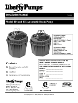
Discharge Flange
PVC solvent weld
1" sch. 40 PVC pipe
Vent Flange
PVC solvent weld
1-1/2" sch. 40 PVC pipe
Discharge and vent flanges
In horizontal orientation
Discharge and vent flanges
In vertical orientation

©Copyright 2016 Liberty Pumps Inc. All rights reserved. 6
3-3-3 Assemble the toilet in accordance to the installation manual(s) provided with it. Be careful when tightening fasteners as to not crack
the porcelain.
3-3-4 To mount the toilet to a concrete floor, drill two holes approximately 2-1/4” deep with a 5/16” masonry drill bit. Insert plastic plugs
into holes. If the floor is wood, bore a pilot hole with a ¼” drill bit. Fasteners not included.
3-3-5 Place the toilet in front of the macerating tank and apply silicone grease to sealing lip of macerator. Then slide the discharge hub of
the toilet into the rubber sealing ring of the macerator.
3-3-6 Place the toilet over the holes in the floor. Slip the plastic china protectors over the lag screws ensure proper orientation. Tighten lag
screws (do not over tighten) and snap plastic caps in place.
3-3-7 Connect the water supply line to the fill valve, located directly below the flush lever, on the bottom of the toilet tank.
3-4 CONNECTION TO THE DISCHARGE AND VENT FLANGES
3-4-1 The Macerator has a PVC discharge flange with an integrated check valve that can be configured in a vertical or horizontal
orientation. Standard 1” schedule 40 PVC pipe can be solvent welded directly to the flange. Excessive amounts of glue should be
avoided. The check valve can be removed from the flange if required. Replacement flanges can be ordered.
http://www.libertypumps.com/Service/ReplacementParts/
3-4-2 A “full-port” ball or gate valve and a union should be installed in the discharge pipe to facilitate the removal of the macerator or to
perform maintenance if required. In addition, a drain off point is also recommend to allow the discharge piping to be drained if
required.
3-4-3 The macerator is equipped with a PVC vent flange, which can be configured in a vertical or horizontal orientation. Standard 1-1/2”
Schedule 40 PVC pipe can be solvent welded directly into the flange.
3-4-4 The macerator must be vented to allow for proper toilet flush performance. Depending on the installation, the product should either
be connected to the stack vent of the dwelling or vented (plumbed) directly outside.
3-4-5 ***Do not use an air admittance valve or a mechanical spring-loaded venting device, as these devices are one-way
valves. The air pressure in and outside the macerating pump unit must be equal, a “cheater” vent will obstruct the airflow in one
direction and prevent proper toilet function.
3-4-6 The Macerator is not designed to support the discharge and vent piping; proper pipe hangers are required.
3-5 CONNECTION TO THE SOIL-STACK OR SEWER
3-5-1 The macerator has a shut-off head of 36 feet. All frictional losses from horizontal runs and elbows need to be accounted for. The
minimum flow rate for 1” PVC sch. 40 pipe is 5 gal/min compared to 3 gal/min for ¾” PVC pipe. If you require a vertical lift, it should
precede any “horizontal” run and should commence as near as possible to the discharge of the macerator. Once you have started
the horizontal run, you may not change directions in a vertical manner.
NOTE: Friction losses from horizontal runs without ¼” per foot pitch will reduce the amount of vertical lift
the system is capable of handling. See sections 3-5-2 and 3-5-3. Consult factory for proper sizing if you
have long runs or multiple elbows. Phone: 1-800-543-2550.
3-5-2 The discharge piping can be made from ¾” or 1” diameter PVC pipe. Use long turn bends and not elbows where possible. The
connection to the soil-stack or sewer pipe should be made with an approved wye fitting.

©Copyright 2016 Liberty Pumps Inc. All rights reserved. 7
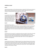
3-5-3 If you wish the unit to pump vertically and horizontally you may calculate 3 feet of vertical lift is equivalent to 30 feet of “horizontal”
run. Each bend or change of direction gives a pressure drop, which must be calculated into the total head of the unit. As an
estimate, reduce discharge height by 3 feet for each 90° bend.
For example: 1” SCH. 40 PVC pipe is used for the discharge and runs horizontally for 1’; then turns 90° and rises 5’ vertical.
Then it travels horizontal with another 90° turn (3 turns in total) and connects with the soil-stack. See illustration below.
Calculations:
Total vertical lift 5’ 5’ vertical
Total Horizontal run 43’ 4.3’ vertical
Total of three 90° elbows 9’ vertical
Now add the three together we get 18.3’ of vertical lift. Reading the
performance curve below indicates the application would result in a flow
rate of 23 gal/min(60Hz).
Tub / Shower should be installed
on a riser to accommodate the P trap
All fixtures must be properly vented

©Copyright 2016 Liberty Pumps Inc. All rights reserved. 8
3-6 CONNECTION TO ELECTRICAL SUPPLY
3-6-1 All wiring should be done in accordance with the applicable electrical codes. The macerating system requires a properly sized
single-phase GFCI (ground fault circuit interrupter) type receptacle. Receptacle should be installed in accordance with local and
state electrical codes. It is recommended that the receptacle be 40 inches away (in a straight line) from a shower or bathtub. If
installation is performed in a basement, the receptacle should be 48 inches from the floor.
3-6-2 If the electrical power receptacle (outlet) is in close proximity to the macerator, the “extra power cord” can be coiled and tucked
away in a large depression designed into the access cover that is located under the right decorative cover.
Risk of electric shock. This pump is supplied with a
grounding-type attachment plug. To reduce the risk of
electric shock, be certain that it is connected to a
properly grounded, grounding-type receptacle.
3-7 EXTENSION PIPE
3-7-1 To install the macerator behind a wall, a Liberty extension pipe kit # K001184 (sold
sperately) will be needed. Included in the kit are an 18.75” long extension pipe, a
decorative trim ring, and a grease packet. Rubber rings seal both ends of the extension
pipe. To prevent tearing, always grease both seals prior to installing the pipe. Slip
the decorative trim ring onto the pipe. To install the pipe, no fasteners are required, slip
the extension pipe over the toilet’s discharge, and then insert the pipe into the
macerator. To finish the installation, fasten the toilet to the floor and secure the
macerator discharge and vent piping. For proper flushing performance, ensure that the
base of the toilet is not below the base of the macerator. Check the extension pipe with
a level, and verify that the pipe is either level or sloped towards the macerator unit and
away from the toilet.
3-7-2 Liberty recommends only one extension pipe be used.
3-8 INSTALLATION TIPS
3-8-1 PIPE SUPPORTS: All sanitary pipe work must be supported in accordance
with the pipe manufacturer’s recommendations. Avoid dipping or trapping,
which may cause the buildup of residual “solids” and subsequent blockage.
3-8-2 BENDS: Wherever possible, long sweeping bends should be used. Do not use
short elbows. If sweeping 90° elbows are not available, use two 45° elbows to
make a 90° turn.
3-8-3 VERTICAL PIPING FIRST: If vertical lift is required, this must precede the
horizontal pipe run.
3-8-4 BATTERY: Battery must be installed AFTER the macerator is connected to the
AC power supply. Failure to follow this procedure could result in the unit not
functioning properly.
3-8-5 DIRECTLY VERTICAL: All vertical lifts should rise as close to the macerator
as possible, allowing only for the need to clear the toilet tank; the initial horizontal run should not exceed 12”.
3-8-6 NO DIAGONAL “UPHILL” PIPE RUNS: All discharge piping from the unit should run either directly vertical or in a horizontal plane
(with a minimum ¼” per foot drop) to the point of discharge. Pipe work must not be installed with a diagonal upward slope from the
unit to the point of discharge.
3-8-7 EASY ACCESS: The unit should be accessible and removable in the event of maintenance being required. During the installation, a
full-port ball valve should be installed near the discharge flange to allow easy service of the unit.
3-8-8 GRAVITY FALL: The unit accepts wastewater by gravity; it does not “vacuum” in water. All inlet pipe work must have a positive
gravity fall (1/4” per foot drop minimum). All horizontal piping from the macerator must also have a ¼” per foot drop to allow free
drainage when the pump stops.
3-8-9 SOIL STACK CONNECTION: All discharge pipe work must be connected to the soil stack by an appropriate and approved
connection like a “tee” or “y” fitting.
3-8-10 PIPE WORK: All pipe work should be copper, PVC, or CPVC. Do not use flexible piping. Hangers should not be less than 4 feet
apart to prevent pipe rattling.
3-8-11 FLUSHING: Macerator is designed to work with a low flow toilet (1.28 gallons per flush).
3-8-12 DISCHARGE: Never discharge directly into an open drain, fixture, manhole or rainwater drainpipe. It is illegal, as it constitutes a
health hazard. Direct connections into sanitary waste systems only shall be acceptable.
3-8-13 FREEZING: Ensure all pipe work susceptible to freezing is adequately insulated or heated. In unheated buildings, the toilet, piping
and macerating unit must be properly winterized. Use plumbers’ anti-freeze or drain completely.
3-8-14 ELECTRICITY: The macerating system must be connected to a Ground Fault Circuit Interrupter (GFCI).
Before attempting any maintenance or servicing, the unit must be disconnected from the power source.
3-8-15 SHOWER: The water height will be 4.5” in the Macerator tank before the unit starts pumping. The shower stall floor must be well
above this level, Liberty recommends at least 6” - 8” to ensure proper shower drainage and prevent any backflow.
Installed position

©Copyright 2016 Liberty Pumps Inc. All rights reserved. 9
Right side
Left side
4-1 ACTIVATING THE UNIT
4-1-1 Ensure that the toilet / tank have been assembled per the instructions provided with the toilet tank.
4-1-2 Ensure any ball or gate valve in the discharge line is in the open (full flow) position.
4-1-3 Open the shut-off valve and let the toilet tank fill up. Look for leaks at connections and verify that the toilet fill valve
float and the flush valve operate freely.
4-1-4 Ensure the macerating unit has both decorative covers installed and is plugged in with the power supply turned on.
The green light should be illuminated. If the green light is blinking, check to confirm the decorative covers are
properly seated.
4-1-5 Deposit a few sheets of toilet paper into the bowl and flush the toilet. There should be no paper remaining in the bowl
after the flush. This should be repeated several times.
4-1-6 Either flushing the toilet or the height of water in the tank activates the Macerator’s adaptive switch system. The unit
will turn on shortly after the toilet is flushed or when a water depth of 4.5” is achieved. The duration of operation will
differ depending upon the installation. Note, the Macerator may not run immediately upon sink usage.
4-2 CAUTIONARY NOTES
4-2-1 The macerating system is designed for human waste and toilet paper.
4-2-2 Do not dispose of acids, alkalis, solvents, oils, paint, paint strippers, food waste, and cotton swabs. Off-the-shelf toilet
cleansers will normally not hurt the macerating unit. During cleaning or when using a plunger the macerator could
turn on.
4-2-3 Do not hang bleach blocks or hypochlorite cleaners in the toilet tank. These solutions have been shown to
deteriorate the plastic and neoprene components of the flush and fill valves, and may cause leaks.
4-2-4 In the event of a power loss, the toilet can be used twice. Use of sanitary fixtures like a sink should be limited. Do not
use shower or tub as the macerating unit will fail to pump until the power is restored.
4-3 MAINTENANCE
The macerator is designed such that every component can easily be serviced or replaced if required.
Risk of electric shock, always disconnect the macerator from the power source before handling or making
adjustments. Health hazard: sharp blades within unit, wear rubber gloves.
4-3-1 Decorative covers: Both the right and left decorative covers sit on the product and are retained with some simple clips
and posts. The right side can be removed by pulling it horizontally away from the macerator and then lifting vertically. The
left decorative cover is secured and positioned by two mating posts on the main cover.
4-3-2 Discharge and Vent Flanges: Both the discharge and vent flanges are fastened to
the main cover and can be removed by unscrewing the four fasteners and pulling the
flange away from the main cover.
4. Operation

©Copyright 2016 Liberty Pumps Inc. All rights reserved. 10
4-3-3 Check Valve: The discharge flange has an integrated check valve. The valve is held in place by a support backing plate
that is also connected to the discharge hose. To access the check valve, first remove the discharge flange from the main
cover by removing 4 screws. Then, remove the hose followed by the two screws. The hose nipple can then be separated
from the flange by pulling it outward. The check valve snaps onto the hose nipple. When reinstalling, the hinge of the
check valve must be aligned with the “notch” in the hose nipple or backing plate. After installation of the hose nipple,
confirm the check valve opens completely.
4-3-4 Access cover: The access cover is secured to the main cover with five fasteners. If required, use the 3/16 Allen wrench
supplied to loosen the fasteners. Once the screws have been removed, the access cover can be lifted upward. Some
manipulation might be necessary if the Macerator is located directly under the toilet’s reservoir tank.
a) Once the access cover is removed, the power cartridge can be slid towards the opening by grasping the handle of
the basket and pulling to the right towards the opening. In some instances, debris might be caught between the tank
and the basket so some manipulation might be required.
b) With the power cartridge fully slid over, the cutters should be in view at the center of the basket. Any obstruction or
object can be removed at this point. The cutters are very sharp and extreme caution should be used.
c) To replace the cutters the 3/16 Allen wrench (supplied) should be inserted into one of the holes located on the
basket floor. This will create a wedge preventing the blade assembly from turning. The locking fastener can be
unscrewed with the use of a 7/16” socket (1/4” drive). Once loose, the screw and cap can be removed by pulling
upward which exposes the two razor blades. Liberty Pumps recommends stainless steel blades, although any
common utility knife style razor blade with two holes can be used as a replacement. When replacing the razor blades
simply insert the blade onto the two pins. The cap and screw should then be replaced.
d) The base of the cutting cartridge can be replaced as well. After removing the razor blades a thin slotted screwdriver
can be inserted into the center hole and once engaged the base can be rotated counterclockwise until it is free.
Once the access cover is removed pull the power
cartridge towards opening

©Copyright 2016 Liberty Pumps Inc. All rights reserved. 11
4-3-5 Accessibility to Motorized cartridge:
The motorized cartridge can be accessed through the access opening or removal of the main cover.
1) Removal of power cartridge through the access opening:
Once the access cover has been removed and the basket is slid towards the opening, the four
fasteners securing the basket can be unscrewed. The basket can then be removed through the
opening followed by the power cartridge.
2) Removal of power cartridge by disassembly of macerator:
If a ball valve was installed in the discharge line, it should be closed to eliminate the possibility of
waste discharging from the discharge pipe. Next, the discharge and vent flanges should be separated
from the main cover by removing 4 screws from each. The main cover can then be detached from the
tank by removing the fasteners on the periphery of the tank. The main cover can then be lifted
upward exposing the power cartridge.
Screw
Base
Utility blade
Cap
To remove cap
Unscrew
fastener
Place Allen
wrench
in hole to prevent
cutter from
turning
Cutting and health hazard,
caution must be used when
handling razor blades.

©Copyright 2016 Liberty Pumps Inc. All rights reserved. 12
The inner connecting power cord running from the switch box to the
motorized cartridge can be detached by unscrewing the compression nut
located at the motorized cartridge.
4-3-6 Removal of blockage from impeller / impeller replacement:
Once the bottom of the motorized cartridge is accessible, the fasteners retaining the volute can be removed and the
volute separated by pulling it away. The impeller chamber can now be cleaned if required, or the impeller can be replaced.
NOTE: the impeller has a left-handed thread. To remove, use a slotted screwdriver to hold the shaft and turn the impeller
clockwise.
4-3-7 Interconnect hose:
A hose connects the discharge of the motor cartridge (pump) to the discharge flange. To remove this hose, follow the
procedure to remove the discharge flange and motorized cartridge. Both ends of the hose are secured with clamps.
4-3-8 Control Switch:
The control switch cartridge is mounted to the main
cover with fasteners. The control has two power cords,
first is the main power cord that plugs into the house
receptacle and the other powers the motorized
cartridge. The motorized cartridge must be removed to
Impeller has a left handed thread
(counterclockwise to tighten)

©Copyright 2016 Liberty Pumps Inc. All rights reserved. 13
disconnect this cord. See instructions under the heading “Accessibility to Motorized cartridge 4-3-5” for details.
4-3-9 Toilet sealing ring:
The seal between the toilet and the macerator consists of a rubber ring connected to the macerator to which the toilet
slides into. The rubber ring stretches and forms a seal around the discharge hub of the toilet. This rubber ring is
replaceable by unclipping the plastic retainer and then pulling the ring outward. Installation is reverse, first slide the rubber
ring onto the macerator followed by the retaining ring.
5-1 BEFORE REFERRING TO TROUBLESHOOTING CHART
5-1-1 Check plumbing system. Flush toilet and ensure water supply is turned on.
5-1-2 Check electrical system. Ensure breaker and receptacle GFCI are on. Check condition of circuit breaker
or fuse. Ensure plug is not loose. If the pumping unit’s thermal overload has activated, it will take about 20
minutes to reactivate.
5-1-3 Ensure decorative covers are installed and fully seated such that safety switch is activated. The green
light should be solid green if safety switch is properly activated.
5-1-4 Check the hydraulic system. Check that the discharge pipe and vent pipe are not blocked.
5-1-5 If the macerating pump turns on intermittently without flushing the toilet or collecting water drainage from
sink, shower, or tub, check for leakage from the toilet tank flush valve.
5. Troubleshooting

©Copyright 2016 Liberty Pumps Inc. All rights reserved. 14
5-2 TROUBLESHOOTING CHART
RISK OF ELECTRIC SHOCK. ALWAYS DISCONNECT THE POWER SUPPLY BEFORE PERFORMING ANY SERVICE TO THE
MACERATING TANK.
PROBLEM
CAUSE
REMEDY
Toilet flushes normally but evacuates or drains
from the bowl slowly
macerator sounds normal and runs for 4
seconds, then after some time runs for 4
seconds.
NO alarm
Water is entering the macerator’s holding tank slowly.
The toilet or discharge extension might
be blocked.
The piping must be cleaned.
Poor vent
Unit must be vented properly to open air to allow water
to enter the macerator tank. Confirm vent is clear.
DO NOT USE A QUICK VENT
Accumulation in the strainer basket
Repetitively flush clean water and allow the macerator to
clear debris. If unit is unable to self-cure the blockage,
the access cover should be removed for manual
cleaning. See Section 4.
Toilet flushes normally but does not evacuate or
drain from the bowl.
macerator sounds normal and runs for 4
seconds then remains off
NO alarm
Water is unable to enter the macerator’s holding tank
The toilet discharge or extension pipe
may be blocked.
The piping must be cleaned.
Unit is not vented correctly
Unit must be vented properly to open air to allow water
to enter the macerator tank. Confirm vent is clear.
DO NOT USE A QUICK VENT

©Copyright 2016 Liberty Pumps Inc. All rights reserved. 15
Toilet flushes normally but does not evacuate or
drain from the bowl.
Macerator starts to run and sounds normal
(running) then stops after 5-10 min.
Restarts after 30 to 60 min.
Alarm is activated
The macerator is unable to evacuate its holding tank and is cycling on thermal overload
Damaged Impeller
Replace impeller
Check valve stuck closed
Confirm the check valve is functioning properly; if not it
must be repaired or replaced.
Internal hose is damaged or
disconnected
Confirm the internal hose is functioning properly; if not it
must be replaced.
If the macerator was installed with a
ball valve in the discharge line, is the
valve open?
Open ball valve
Air lock
The volute has a passage way to allow trapped air to
escape, this passage way must be cleaned of
obstruction
Volute inlet plugged
The volute’s inlet, located on the bottom of the pump
cartridge, requires cleaning.
Toilet Flushes normally but macerator does not
turn on or just hums
Green light is on steady (solid)
The macerator is jammed
The cutter or impeller are jammed
preventing the motor from turning
Clear the cutter or impeller of blockage
Internal motor problem
The pump cartridge must be replaced
Waste build up in the toilet bowl
The toilet has an inadequate flush volume, possible blockage of the strainer basket, or
improper venting.
Inadequate water level in the reservoir
tank
Check and / or adjust the water fill mechanism so that
the water level matches the reference line in the tank
Strainer basket requires cleaning
Clear debris from the strainer basket
Unit is not vented correctly
Unit must be vented properly to open air to allow water
to enter the macerator tank. Confirm vent is clear.
DO NOT USE A QUICK VENT

©Copyright 2016 Liberty Pumps Inc. All rights reserved. 16
The Macerator does not start up
Green light is off
No electrical power
The macerator is either not plugged in,
supply breaker is turned off, or GFCI
receptacle has tripped.
Check electrical power source
The Macerator has no lights when power is
connected
All lights on user interface panel are not lit
No electrical power or battery protection mode
The macerator is either not plugged in,
supply breaker is turned off, or GFCI
receptacle has tripped.
Check electrical power source
Control system is in battery protection
mode.
1. Unplug macerator from receptacle
2. Remove the 9V battery that powers the alarm
3. Plug the macerator back into the receptacle
4. Re-install the 9V battery
The Macerator does not start up
Green light is flashing
The Macerator has electrical power, safety switch is off.
The decorative cover is not installed
Both halves of the decorative cover must be installed
and fitted properly on the unit.
The right decorative cover, the one
over the access cover should have a
magnet located on a post. This magnet
activates a safety switch
Replace magnet or entire right decorative cover
The macerator pulses for no apparent reason
General plumbing
Water leakage from the toilet’s
reservoir
Check flush valve and related components in the
reservoir tank
Check valve failure of the Macerator
The discharge flange contains the check valve which
either requires cleaning or replacement
During a pumping cycle a rattling noise is
emanating from the Macerator
Solid debris in basket
Solid object larger than ½” is trapped
in the cutting basket of the Macerator
The access cover should be removed for manual
cleaning. See section 4
Alarm sounds frequently
Pump is unable to evacuate tank
Damaged Impeller
Replace impeller
Volute inlet clogged
Clean volute’s inlet
Internal hose is damaged
Confirm the internal hose is functioning properly; if not it
must be replaced.

©Copyright 2016 Liberty Pumps Inc. All rights reserved. 17
Air lock
The volute has a passage-way to allow trapped air to
escape. This passage-way must be cleaned of
obstruction
Application
The pumping capacity has been exceeded by the rate of
incoming water. Either reduce flow coming into the
macerator or reduce the pumping head.
Water backs up into shower tray
Alarm is not activated
General plumbing
Blockage or inadequate slope of pipe
Clear blockage in piping, or increase pitch of discharge
pipe. Typically ¼” drop per foot is adequate for a gravity
drain.
The inlet flappers of the Macerator are
not functioning
Clear any buildup in the Macerator holding tank that is
preventing the flappers from opening
Water backs up into shower tray
Alarm is activated
General plumbing or system is backing up
Damaged Impeller
Replace impeller
Volute inlet clogged
Clean volute’s inlet
Internal hose is damaged
Confirm the internal hose is functioning properly; if not it
must be replaced.
Air lock
The volute has a passage way to allow trapped air to
escape, this passage way must be cleaned of
obstruction
Incoming flow rate is greater than
pump capacity
The unit is capable of handling up to two shower heads
– multiple (3 and up) shower heads should be avoided.
Check valve failure of the Macerator
The discharge flange contains the check valve which
either requires cleaning or replacement
During the draining of the bathtub the alarm
sounds and / or water backs up into the toilet
General plumbing
The inflow is greater than the
macerator can handle
A ball valve should be installed between the tub and
macerator – throttle down or partially close the ball valve
until the macerator can handle the drainage rate from
the tub.
Macerator is noisy when running
General plumbing
Rattling piping
Both the discharge and vent plumbing should be
secured using the appropriate pipe clamp.
Foreign object in cutter basket
The access cover should be removed for manual
cleaning see section 4

©Copyright 2016 Liberty Pumps Inc. All rights reserved. 18
NOTE: Liberty Pumps, Inc. assumes no responsibility for damage or injury due to disassembly in the field. Disassembly, other than at
Liberty Pumps or its authorized service centers, automatically voids warranty.
Liberty Pumps, Inc. warrants that pumps of its manufacture are free from all factory defects in material and workmanship for a period of
3 years from the date of purchase. The date of purchase shall be determined by a dated sales receipt noting the model and serial
number of the pump. The dated sales receipt must accompany the returned pump if the date of return is more than 3 years from the
"CODE" (date of manufacture) number noted on the pump nameplate.
The manufacturer's obligation under this Warranty shall be limited to the repair or replacement of any parts found by the manufacturer
to be defective, provided the part or assembly is returned freight prepaid to the manufacturer or its authorized service center, and
provided that none of the following warranty-voiding characteristics are evident.
The manufacturer shall not be liable under this Warranty if the product has not been properly installed; if it has been disassembled,
modified, abused or tampered with; if the electrical cord has been cut, damaged or spliced; if the pump discharge has been reduced in
size; if the pump has been used in water temperatures above the advertised rating, or water containing sand, lime, cement, gravel or
other abrasives; if the product has been used to pump chemicals or hydrocarbons; if a non-submersible motor has been subjected to
excessive moisture; or if the label bearing the serial, model and code number has been removed. Liberty Pumps, Inc. shall not be
liable for any loss, damage or expenses resulting from installation or use of its products, or for consequential damages, including costs
of removal, reinstallation or transportation.
There is no other express warranty. All implied warranties, including those of merchantability and fitness for a particular purpose, are
limited to three years from the date of purchase.
This Warranty contains the exclusive remedy of the purchaser, and, where permitted, liability for consequential or incidental damages
under any and all warranties are excluded.
7. 3 Year Limited Warranty
7000 Apple Tree Avenue
Bergen, NY 14416
Phone: (800) 543-2550
Fax: (585) 494-1839
www.libertypumps.com
/