
Dell PowerVault 2xxS Storage Systems SCSI Backplane Board Replacement Instructions 1
Dell™ PowerVault™ 2xxS
Storage Systems SCSI Backplane
Board Replacement Instructions
This document describes how to replace the small computer system interface
(SCSI) backplane board in the Dell PowerVault 2xxS storage system. To access
the SCSI backplane board, all of the components in the storage system must
be removed.
Before you perform any of the procedures in this section, read the following
warning for your personal safety and to prevent damage to the storage system
from electrostatic discharge (ESD).
WARNING: The power supplies in this system produce energy haz-
ards, which can cause bodily harm. Only trained service technicians
are authorized to perform the procedures in this document.
WARNING: FOR YOUR PERSONAL SAFETY AND PROTECTION OF THE
EQUIPMENT WHEN WORKING INSIDE THE STORAGE SYSTEM:
Before you start to work on the storage system, perform the following
steps in the sequence listed:
1. Turn off the storage system.
2. Disconnect the storage system from its power source(s).
3. Disconnect any communications cables.
4. Wear a wrist grounding strap, and clip it to an unpainted metal sur-
face, such as a part of the chassis.
If a wrist grounding strap is not available, touch the fan guard or some
other unpainted metal surface on the back of the chassis to discharge
any static charge from your body.
See the Dell PowerVault 200S, 201S, 210S, and 211S Storage Systems Installa-
tion and Service Guide for cabling and power information.
System Preparation
If the storage system is installed in a rack, it must be removed from the rack
before the SCSI backplane board can be replaced. Likewise, the storage sys-
tem must be removed from its enclosure if it is used in a stand-alone
configuration. See the Dell PowerVault 200S, 201S, 210S, and 211S Storage
Systems Installation and Service Guide for rack and stand-alone information.

2 Dell PowerVault 2xxS Storage Systems SCSI Backplane Board Replacement Instructions
SCSI Backplane Replacement Overview
Use the following procedures, in the order listed, to replace the SCSI back-
plane board.
1. Remove the hard-disk drives.
2. Remove the power supplies.
3. Remove the cooling fans.
4. Remove the enclosure services modules or enclosure services expander
modules.
5. Remove the component mounting bracket.
6. Remove the dual-bus split backplane module.
7. Remove the SCSI backplane board.
8. Install the replacement SCSI backplane board.
9. Install the dual-bus split backplane module on the replacement SCSI back-
plane board.
10. Install the component mounting bracket.
11. Install the enclosure services or enclosure services expander modules.
12. Install the cooling fans.
13. Install the power supplies.
14. Install the hard-disk drives.
Each procedure is described in the following sections.
Remove the SCSI Hard-Disk Drives
CAUTION: Note the location of the SCSI hard-disk drives as you
remove them from the drive bays. During the installation procedure
(found later in this document), you must return the SCSI hard-disk
drives to the same drive bays from which they were removed.
To remove the SCSI hard-disk drives from the drive bays, perform the following
steps.
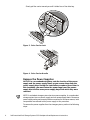
NOTE: The storage system comes with either a silver, swing-out lock bar or a
black, removable lock bar, which secures the hard-disk drives in their drive bay
slots.
1. Using the key, unlock the keylock.
2. For a storage system with the silver, swing-out lock bar, using your finger-
tips, tap up on the lock bar. The lock bar easily swings out and down, just
below the level of the drive bays (see Figure 1).

Dell PowerVault 2xxS Storage Systems SCSI Backplane Board Replacement Instructions 3
If the storage system is in a stand-alone configuration, tap the bar to the
left. The lock bar springs out. Swing the lock bar to the right of the drive
bays.
Figure 1. Keylock and Swing-out Lock Bar (Silver)
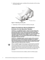
NOTICE: To avoid damage, do not pull the tab handle of the
black, removable lock bar out too far. Figure 2 shows the lock bar
at an exaggerated angle (after it is completely out of its hole).
For a storage system with the black, removable lock bar:
a. Grasp the tab handle on the lock bar and gently pull it toward you,
about 1/2-inch away from the unlocked keylock.
b. Slide the left end of the lock bar to the right to remove it from its hole
(see Figure 2).
Figure 2. Keylock and Removable Lock Bar (Black)
3. Remove the hard-disk drives.
NOTICE: Handle the hard-disk drives with care. The carriers pro-
vide some protection, but the hard-disk drives can be damaged
by rough handling. When removing the hard-disk drives from the
storage system, place them on a padded surface. Never drop the
hard-disk drives.
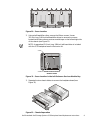
Release the hard-disk drive carrier by pressing down on the hard-disk drive
carrier lock (see Figure 3) and swing the carrier handle down (see Figure 4).
lock bar
keylock
enclosure status indicators
drive bays
key lock
lock bar
tab handle

4 Dell PowerVault 2xxS Storage Systems SCSI Backplane Board Replacement Instructions
Slowly pull the carrier toward you until it slides free of the drive bay.
Figure 3. Drive Carrier Lock
Figure 4. Drive Carrier Handle
Remove the Power Supplies
NOTICE: In a nonredundant system, note the location of the power
supply and the power-supply blank as you remove them from the
power-supply bays. During the installation procedure (found later in
this document), you must return the power supply and the power-
supply blank to the same power-supply bays from which they were
removed.
NOTE: A redundant storage system has two power supplies. A nonredundant
storage system has one power supply and one power-supply blank. Because a
power supply and a power-supply blank are removed in the same manner, both
components are referred to as a power supply in this procedure.
To remove the power supplies from the storage system, perform the following
steps:

Dell PowerVault 2xxS Storage Systems SCSI Backplane Board Replacement Instructions 5
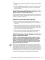
1. Using a Phillips-head screwdriver, turn the two captive screws counter-
clockwise to release the power supply from the power-supply bay.
2. Holding the handle on the power supply, carefully pull the power supply out
of the power-supply bay (see Figure 5).
NOTE: The power-supply handle is provided to ease the task of pulling the
power supply free from the bay. Do not use the handle to carry the Dell
PowerVault 2xxS storage system.
Figure 5. Removing a Power Supply on a Redundant System
3. Repeat steps 1 and 2 to remove the remaining power supply.
Remove the Cooling Fans
NOTICE: In a nonredundant system, note that the cooling-fan blank
is located in the right cooling-fan bay. During the installation proce-
dure (found later in this document), you must return the cooling-fan
blank to the right cooling-fan bay.
NOTE: A redundant storage system has three cooling fans. A nonredundant
storage system has two cooling fans and one cooling-fan blank. Because a
cooling fan and a cooling-fan blank are removed in the same manner, both
components are referred to as a cooling fan in this procedure.
To remove the cooling fans from the storage system, perform the following
steps:
1. Using a Phillips-head screwdriver, turn the two captive screws counter-
clockwise to release the cooling fan from the cooling-fan bay.
captive screws (2)

6 Dell PowerVault 2xxS Storage Systems SCSI Backplane Board Replacement Instructions
2. Holding the captive screws, carefully pull the cooling fan out of the cooling-
fan bay (see Figure 6).
Figure 6. Removing a Cooling Fan
3. Repeat steps 1 and 2 to remove the remaining cooling fans.
Remove the Enclosure Services Modules or
Enclosure Services Expander Modules
NOTICE: In a nonredundant system, note the location of the enclo-
sure services module, the enclosure services expander module, or
the terminator blank as you remove them from the module bays.
During the installation procedure (found later in this document), you
must return the enclosure services module, enclosure services
expander module, or the terminator blank to the same module bays
from which they were removed.
NOTICE: In a redundant system, note the location of the enclosure
services or enclosure services expander modules as you remove
them from the module bays. During the installation procedure (found
later in this document), you must return these modules to the same
module bays from which they were removed.
NOTE: A redundant storage system has two enclosure services or enclosure
services expander modules. A nonredundant storage system has one enclo-
sure services module or one enclosure services expander module and one
terminator blank. Because an enclosure services module, enclosure services
expander module, and a terminator blank are removed in the same manner, all
three components are referred to as an enclosure services module in this
procedure.
To remove the enclosure services modules, perform the following steps:
captive screws (2)

Dell PowerVault 2xxS Storage Systems SCSI Backplane Board Replacement Instructions 7
1. Using a Phillips-head screwdriver, loosen the captive screw at the top of
the enclosure services module.
2. Grasp the handle on the enclosure services module and pull it from the
module bay (see Figure 7).
Figure 7. Enclosure Services Module Removal
3. Repeat steps 1 and 2 to remove the remaining enclosure services module.
Remove the Component Mounting Bracket
To remove the component mounting bracket, perform the following steps:
1. Using a Phillips-head screwdriver, remove the two screws that secure the
component mounting bracket to the chassis (see Figure 8).
2. Lift the component mounting bracket slightly and slide it out of the chassis.
captive screw

8 Dell PowerVault 2xxS Storage Systems SCSI Backplane Board Replacement Instructions
Figure 8. Removing the Component Mounting Bracket
Remove the Dual-Bus Split Backplane Module
Carefully hold the dual-bus split backplane module on both sides and, using a
wiggle motion, pull the module from the backplane board (see Figure 9).
Figure 9. Dual-Bus Split Backplane Module Location
Remove the SCSI Backplane Board
To remove the SCSI backplane board, perform the following steps:
1. Looking in the rear of the storage system, locate the fifteen screws that
secure the two halves of the chassis together. There are nine across the
top and six across bottom of the backplane board (see Figure 10).
dual-bus split backplane module

Dell PowerVault 2xxS Storage Systems SCSI Backplane Board Replacement Instructions 9
Figure 10. Screw Location
2. Using a ball-head Allen driver, remove the fifteen screws. Use an
11.5-inch–long, 5/64-inch ball-head Allen driver to remove the screws
located inside the enclosure services module bays on the left and right side
of the chassis (see Figure 11).
NOTE: A magnetized 11.5-inch–long, 5/64-inch ball-head driver is included
with the SCSI backplane board in the service kit.
Figure 11. Screw Location in the Left Enclosure Services Module Bay
3. Separate the two chassis halves to remove the backplane board (see
Figure 12).
Figure 12. Chassis Separation
image shown without chassis
screw
screw
left-side enclosure services
module is shown

10 Dell PowerVault 2xxS Storage Systems SCSI Backplane Board Replacement Instructions
Install the Replacement SCSI Backplane Board
To install the replacement SCSI backplane board, perform the following steps:
1. Place the board between the chassis halves. Ensure that the board is right
side up and the dual-bus split backplane module faces the back half while
the eight hard-disk drive connectors face the front half.
2. Using the magnetized 11.5-inch–long, 5/64-inch ball-head Allen driver,
thread two screws through the left enclosure services module bay,
through the screw holes in the backplane board, and into the screw holes
of the front half of the chassis. Turn the screws until they catch in the
screw holes of the front half of the chassis. Do not tighten the screws at
this time. Install the two screws in the right enclosure services module bay
in the same manner.
NOTE: The magnetized 11.5-inch–long, 5/64-inch ball-head Allen driver
(included in the service kit) makes it easier to install the screws in the
enclosure services module bays.
3. Thread the eleven remaining screws through the inside of the component
area of the back chassis half, through the screw holes in the backplane
board, and into the screw holes of the front half of the chassis. Turn the
screws until they catch in the screw holes of the front half of the chassis.
Do not tighten the screws at this time.
NOTE: If the front half of the chassis is slightly bowed down, making it dif-
ficult to align the screw holes, try installing a hard-disk drive temporarily
into one of the center drive bays. The hard-disk drive should straighten the
bow in the chassis, making it easier to thread the screws. Remove the
hard-disk drive when all the screws are inserted.
4. Carefully insert the left enclosure services module or enclosure services
expander module into the left module bay. Push the module all the way to
the back of the bay and at the same time adjust the backplane board so
that the board connector aligns with the module connector. Push the mod-
ule until it is seated in the board connector.
NOTE: Temporarily installing the enclosure services modules or enclosure
services expander modules and seating their connectors to the connectors
on the backplane board ensures that the backplane board will be aligned as
the two chassis halves are screwed together.
5. Using a Phillips-head screwdriver, tighten the screw to secure the enclo-
sure services module or enclosure services expander module to the
chassis.
6. Repeat steps 4 and 5 for the right (second) enclosure services module,
enclosure services expander module, or terminator blank.
7. Tighten the eleven screws on the inside of the component area to secure
the chassis front, backplane board, and chassis back together.
8. Using a Phillips-head screwdriver, loosen the captive screws at the top of
the enclosure services modules.

Dell PowerVault 2xxS Storage Systems SCSI Backplane Board Replacement Instructions 11
9. Remove both enclosure services modules or enclosure services expander
modules.
10. Using a ball-head Allen driver, tighten the two screws in the left enclosure
services module bay and then tighten two screws in the right enclosure
services module bay.
Install the Dual-Bus Split Backplane Module on the
Replacement SCSI Backplane Board
Install the replacement dual-bus split backplane module onto the replacement
backplane board. The dual-bus split backplane module is keyed, but care must
be taken not to bend the contact pins.
Install the Component Mounting Bracket
To install the component mounting bracket, perform the following steps:
1. Carefully insert the component mounting bracket into the back of the stor-
age system.
2. Slowly slide the bracket all the way into the housing. Some up-down and
side-to-side motion may be necessary to slide the bracket in. Ensure that
the center guide tab at the bottom of the housing goes into the slot on the
center support of the component mounting bracket.
3. Insert the two screws and, using a Phillips-head screwdriver, tighten the
screws to secure the component mounting bracket to the chassis.
Install the Enclosure Services Modules or Enclosure
Services Expander Modules
NOTICE: In a nonredundant system, install the enclosure services
module or enclosure services expander module and the terminator
blank in the same module bays from which they were removed.
NOTICE: In a redundant system, install the enclosure services mod-
ules or enclosure services expander modules in the same module
bays from which they were removed.
NOTE: A redundant storage system has two enclosure services modules or
enclosure services expander modules. A nonredundant storage system has a
single expansion services module or enclosure services expander module and
a terminator blank. Because an enclosure services module, enclosure services
expander module, and a terminator blank install in the same manner, all these
components are referred to as an enclosure services module in this procedure.
To install the enclosure services modules, perform the following steps:

12 Dell PowerVault 2xxS Storage Systems SCSI Backplane Board Replacement Instructions
1. Carefully insert the replacement enclosure services module into the mod-
ule bay. Push the module all the way to the back of the bay until it is seated
in the connector.
2. Using a Phillips-head screwdriver, tighten the captive screw at the top of
the enclosure services module to secure the module to the chassis.
3. Repeat steps 1 and 2 to install the remaining enclosure services module.
Install the Cooling Fans
NOTICE: In a nonredundant system, install the cooling-fan blank in
the same cooling-fan bay from which it was removed.
NOTE: In a redundant storage system, there are three cooling fans. In a nonre-
dundant storage system there are two cooling fans and one cooling-fan blank.
Because a cooling fan and a cooling-fan blank are installed in the same manner,
both components are referred to as a cooling fan in this procedure.
To install the cooling fans, perform the following steps:
1. Carefully slide the cooling fan into the empty cooling-fan bay. Push the
cooling fan all the way to the back of the bay until it is seated in the
connector.
2. Using a Phillips-head screwdriver, turn the two captive screws clockwise
until the cooling fan is secured to the cooling-fan bay.
3. Repeat steps 1 and 2 to install the remaining cooling fans.
Install the Power Supplies
NOTICE: In a nonredundant system, install the power supply and the
power-supply blank in the same power-supply bays from which they
were removed.
NOTE: In a redundant storage system, there are two power supplies. In a non-
redundant storage system there is one power supply and one power-supply
blank. Because a power supply and a power-supply blank are installed in the
same manner, both components are referred to as a power supply in this
procedure.
To install the power supplies, perform the following steps:
1. Carefully slide the power supply into the empty power-supply bay. Push the
power supply all the way to the back of the bay until it is seated in the
connector.
2. Using a Phillips-head screwdriver, turn the two captive screws clockwise
until the new power supply is secured to the power-supply bay.
3. Repeat steps 1 and 2 to install the remaining power supply.

Dell PowerVault 2xxS Storage Systems SCSI Backplane Board Replacement Instructions 13
Install the Hard-Disk Drives
NOTICE: Install the hard-disk drives in the same drive bays from
which they were removed.
NOTICE: Handle the hard-disk drives with care. The carriers provide
some protection, but the hard-disk drives can be damaged by rough
handling. When installing hard-disk drives, use gentle pressure to
slide them in the drive bays. Insert them slowly; never use force.
To install the hard-disk drives, perform the following steps:
1. Carefully slide the hard-disk drive into the bay (see Figure 13). When the
hard-disk drive is almost all the way into the bay, the carrier handle flips up.
Figure 13. Installing a SCSI Hard-Disk Drive (System Shown with a
Swing-out Lock Bar)
2. Close the handle to draw the drive carrier into the bay and lock the drive in
place.
3. Repeat steps 1 and 2 to install the remaining hard-disk drives.
4. For a storage system with a silver swing-out lock bar, raise the lock bar to
the lock position. The lock bar slips down into a detent. This holds the lock
bar in the lock position.
If the storage system is in a stand-alone configuration, swing the lock bar
to the left into the lock position. The lock bar slips to the right into a detent.
This holds the lock bar in the lock position.
For a storage system with a black, removable lock bar, place the left end of
the lock bar into its hole in the left side of the front panel. Then, align the
lock bar with the locking mechanism by the keylock (see Figure 14).

14 Dell PowerVault 2xxS Storage Systems SCSI Backplane Board Replacement Instructions
.
Figure 14. Installing the Lock Bar (System Shown with a Removable
Lock Bar)
5. Place the key in the keylock and turn it to the locked position. Remove the
key from the keylock.
SCSI Backplane Board Replacement Completion
NOTE: For information on installation, cabling, and powering on the storage
system, see the Dell PowerVault 200S, 201S, 210S, and 211S Storage Systems
Installation and Service Guide.
After replacing the SCSI backplane board, complete the procedure by perform-
ing the following steps:
1. Install the storage system in the rack from which it was removed. If the
storage system was used in a stand-alone configuration, install the storage
system in the stand-alone enclosure.
2. Connect the communication cable(s) coming from the host computer to
the storage system.
3. Connect the power cable(s) from the storage system to the power
source(s).
4. Turn on the storage system.
key lock
lock bar
-
 1
1
-
 2
2
-
 3
3
-
 4
4
-
 5
5
-
 6
6
-
 7
7
-
 8
8
-
 9
9
-
 10
10
-
 11
11
-
 12
12
-
 13
13
-
 14
14


Dell PowerVault 201S (SCSI) User guide
- Type
- User guide
- This manual is also suitable for
Ask a question and I''ll find the answer in the document
Finding information in a document is now easier with AI
Related papers
-
Dell 210S User manual
-
-
Dell PowerVault 220S (SCSI) User manual
-
-
Dell PowerVault 735N (Rackmount NAS Appliance) User manual
-
Dell E04J001 User manual
-
-
-
Dell PowerVault MD3600f User manual
-