Sony XDCAM PDW-700 Operating instructions
- Category
- Camcorders
- Type
- Operating instructions

PROFESSIONAL DISC CAMCORDER
PDW-700
OPERATION MANUAL [English]
1st Edition
The supplied CD-ROM includes operation manuals for the PDW-700
Professional Disc Camcorder (English, Japanese, French, German,
Italian, Spanish and Chinese versions) in PDF format.
For more details, see “Using the CD-ROM manual” on page 12.
Sony Corporation
Printed on recycled paper.
PDW-700
(SYL)
3-297-517-02 (2)
Printed in Japan
2008.03.13
© 2008
PROFESSIONAL DISC CAMCORDER PDW-700

2
This Professional Disc Camcorder is
classified as a CLASS 1 LASER PRODUCT.
Laser diode properties
Wavelength: 400 to 410 nm
Emission duration: Continuous
Laser output power: 135 mW (max. of
pulse peak), 65 mW (max. of CW)
Standard: IEC60825-1 (2001)
Egenskaber for laserdiode
Bølgelængde: 400 til 410 nm
Strålingsvarighed: Kontinuerlig
Afgivet lasereffekt: 135 mW (maks
stråletoppunkt), 65 mW (maks ved
kontinuerlig stråling)
Standard: IEC60825-1 (2001)
Tekniska data för laserdiod
Våglängd: 400 till 410 nm
Emissionslängd: Kontinuerlig
Laseruteffekt: 135 mW (max. för
pulstopp), 65 mW (max. för kontinuerlig
våg)
Standard: IEC60825-1 (2001)
Egenskaper for laserdiode
Bølgelengde: 400 til 410 nm
Strålingsvarighet: Uavbrutt
Utgangseffekt for laser: 135 mW (maks av
pulshøyde), 65 mW (maks av CW)
Standard: IEC60825-1 (2001)
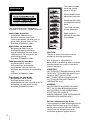
This label is located
inside the outside
panel of the unit.
Denna etikett finns på
apparatens ovansida.
Denne mærkat sidder
på apparatets øverste
panel.
Tämä kyltti sijaitsee
laitteen yläpinnalla.
Dette merket er
plassert på oversiden
av produktet.
CAUTION
The use of optical instruments with this
product will increase eye hazard.
Use of controls or adjustments or
performance of procedures other than those
specified herein may result in hazardous
radiation exposure.
VAROITUS!
LAITTEEN KÄYTTÄMINEN MUULLA KUIN
TÄSSÄ KÄYTTÖOHJEESSA MAINITULLA
TAVALLA SAATTAA ALTISTAA
KÄYTTÄJÄN TURVALLISUUSLUOKAN 1
YLITTÄVÄLLE NÄKYMÄTTÖMÄLLE
LASERSÄTEILYLLE.
VARNING
OM APPARATEN ANVÄNDS PÅ ANNAT
SÄTT ÄN I DENNA BRUKSANVISNING
SPECIFICERATS, KAN ANVÄNDAREN
UTSÄTTAS FÖR OSYNLIG
LASERSTRÅLNING, SOM ÖVERSKRIDER
GRÄNSEN FÖR LASERKLASS 1.
For the customers in the U.S.A.
This equipment has been tested and found to
comply with the limits for a Class B digital
device, pursuant to Part 15 of the FCC Rules.
These limits are designed to provide
reasonable protection against harmful
WARNING

3
interference in a residential installation. This
equipment generates, uses, and can radiate
radio frequency energy and, if not installed
and used in accordance with the instructions,
may cause harmful interference to radio
communications. However, there is no
guarantee that interference will not occur in a
particular installation. If this equipment does
cause harmful interference to radio or
television reception, which can be
determined by turning the equipment off and
on, the user is encouraged to try to correct
the interference by one or more of the
following measures:
— Reorient or relocate the receiving
antenna.
— Increase the separation between the
equipment and receiver.
— Connect the equipment into an outlet on a
circuit different from that to which the
receiver is connected.
— Consult the dealer or an experienced
radio/TV technician for help.
You are cautioned that any changes or
modifications not expressly approved in this
manual could void your authority to operate
this equipment.
All interface cables used to connect
peripherals must be shielded in order to
comply with the limits for a digital device
pursuant to Subpart B of Part 15 of FCC
Rules.
If you have any questions about this product,
you may call;
Sony Customer Information Service Center
1-800-222-7669 or http://www.sony.com/
For the State of California, USA only
Perchlorate Material - special handling may
apply, See
www.dtsc.ca.gov/hazardouswaste/perchlorate
Perchlorate Material : Lithium battery
contains perchlorate.
For the customers in Europe
This product with the CE marking complies
with the EMC Directive issued by the
Commission of the European Community.
Compliance with this directive implies
conformity to the following European
standards:
• EN55103-1: Electromagnetic Interference
(Emission)
• EN55103-2: Electromagnetic Susceptibility
(Immunity)
This product is intended for use in the
following Electromagnetic Environments: E1
(residential), E2 (commercial and light
industrial), E3 (urban outdoors), E4
(controlled EMC environment, ex. TV studio).
The manufacturer of this product is Sony
Corporation, 1-7-1 Konan, Minato-ku, Tokyo,
Japan.
The Authorized Representative for EMC and
product safety is Sony Deutschland GmbH,
Hedelfinger Strasse 61, 70327 Stuttgart,
Germany. For any service or guarantee
matters please refer to the addresses given
in separate service or guarantee documents.
Declaration of Conformity
Trade Name: SONY
Model: PDW-700
Responsible party:
Sony Electronics Inc.
Address: 16530 Via Esprillo,
San Diego, CA 92127
U.S.A.
Telephone Number:
858-942-2230
This device complies with part 15 of the
FCC Rules. Operation is subject to the
following two conditions: (1) this device
may not cause harmful interference, and
(2) this device must accept any
interference received, including
interference that may cause undesired
operation.

4
For the customers in Taiwan only
Cette étiquette est
placée à l'intérieur du
panneau extérieur de
l'appareil.
ATTENTION
L’emploi d’instruments optiques avec ce
produit augmentera les risques pour les
yeux.
L’emploi de commandes ou ajustements ou
l’exécution de procédures autres que celles
spécifiées ici peut provoquer une exposition
dangereuse au rayonnement.
Pour les clients en Europe
Ce produit portant la marque CE est
conforme à la Directive sur la compatibilité
électromagnétique (EMC) émise par la
Commission de la Communauté
européenne.
La conformité à cette directive implique la
conformité aux normes européennes
suivantes :
• EN55103-1 : Interférences
électromagnétiques (émission)
• EN55103-2 : Sensibilité électromagnétique
(immunité)
Ce produit est prévu pour être utilisé dans les
environnements électromagnétiques
suivants : E1 (résidentiel), E2 (commercial et
industrie légère), E3 (urbain extérieur) et E4
(environnement EMC contrôlé, ex. studio de
télévision).
Le fabricant de ce produit est Sony
Corporation, 1-7-1 Konan, Minato-ku, Tokyo,
Japon.
Le représentant autorisé pour EMC et la
sécurité des produits est Sony Deutschland
GmbH, Hedelfinger Strasse 61, 70327
Stuttgart, Allemagne. Pour toute question
concernant le service ou la garantie, veuillez
consulter les adresses indiquées dans les
documents de service ou de garantie
séparés.
Dieses Gerät ist als CLASS 1 LASER
PRODUCT eingestuft.
Daten der Laserdiode
Wellenlänge: 400 bis 410 nm
Emissionsdauer: Ununterbrochen
Laser-Ausgangsleistung: 135 mW (max.
Impulsspitze), 65 mW (max. Dauerstrich)
Standard: IEC60825-1 (2001)
AVERTISSEMENT
WARNUNG

5
Dieser Aufkleber
befindet sich hinter
der Außenabdeckung
des Geräts.
VORSICHT
Der Einsatz von optischen Hilfen verstärkt
die Gefahr von Augenschäden.
Bei Betätigung von Bedien- und Einstellteilen
oder Ausführung von Bedienvorgängen, die
nicht ausdrücklich in dieser
Bedienungsanleitung aufgeführt sind, droht
u.U. die Einwirkung gefährlicher
Laserstrahlung.
Für Kunden in Europa
Dieses Produkt besitzt die CE-
Kennzeichnung und erfüllt die EMV-
Richtlinie der EG-Kommission.
Angewandte Normen:
• EN55103-1: Elektromagnetische
Verträglichkeit (Störaussendung)
• EN55103-2: Elektromagnetische
Verträglichkeit (Störfestigkeit)
Für die folgenden elektromagnetischen
Umgebungen: E1 (Wohnbereich), E2
(kommerzieller und in beschränktem Maße
industrieller Bereich), E3 (Stadtbereich im
Freien) und E4 (kontrollierter EMV-Bereich,
z.B. Fernsehstudio).
Der Hersteller dieses Produkts ist Sony
Corporation, 1-7-1 Konan, Minato-ku, Tokyo,
Japan.
Der autorisierte Repräsentant für EMV und
Produktsicherheit ist Sony Deutschland
GmbH, Hedelfinger Strasse 61, 70327
Stuttgart, Deutschland. Bei jeglichen
Angelegenheiten in Bezug auf Kundendienst
oder Garantie wenden Sie sich bitte an die in
den separaten Kundendienst- oder
Garantiedokumenten aufgeführten
Anschriften.

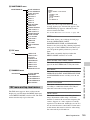
Table of Contents
6
Table of Contents
Foreword .................................................................................................... 12
Before use........................................................................................ 12
Using the CD-ROM manual............................................................ 12
Chapter 1 : Overview
Features ...................................................................................................... 13
Locations and Functions of Parts and Controls...................................... 14
Power supply................................................................................... 14
Accessory attachments.................................................................... 15
Operating and connectors section ................................................... 16
HDVF-20A viewfinder (optional)................................................... 29
Status display on the viewfinder screen.......................................... 30
Chapter 2 : Preparations
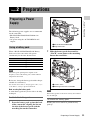
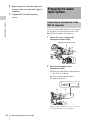
Preparing a Power Supply ........................................................................ 33
Using a battery pack........................................................................ 33
Using AC power.............................................................................. 34
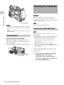
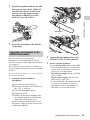
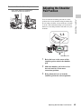
Attaching the Viewfinder .......................................................................... 34
Attaching the HDVF-20A/C35W ................................................... 34
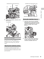
Adjusting the viewfinder position................................................... 35
Moving the viewfinder shoe up....................................................... 35
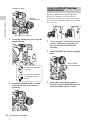
Using the BKW-401 Viewfinder Rotation Bracket ........................ 36
Detaching the eyepiece ................................................................... 37
Adjusting the viewfinder focus and screen ..................................... 37
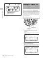
Setting the Area of Use .............................................................................. 38
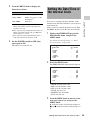
Setting the Date/Time of the Internal Clock ........................................... 39
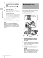
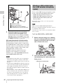
Mounting the Lens..................................................................................... 40
Adjusting the Flange Focal Length .......................................................... 41
Preparing the Audio Input System .......................................................... 42
Connecting a microphone to the MIC IN connector....................... 42
Connecting microphones to the AUDIO IN connectors ................. 43
Attaching a UHF portable tuner (for a UHF wireless microphone
system)...................................................................................... 44
Connecting line input audio equipment .......................................... 46

Table of Contents
7
Tripod Mounting ....................................................................................... 47
Connecting a Video Light ......................................................................... 48
Using the Shoulder Strap .......................................................................... 48
Adjusting the Shoulder Pad Position ....................................................... 49
Connecting the Remote Control Unit ...................................................... 50
Chapter 3 : Adjustments and Settings for Shooting
Recording Format...................................................................................... 52
Adjusting the Black Balance and the White Balance ............................. 52
Adjusting the black balance ............................................................ 53
Adjusting the white balance............................................................ 54
Setting the Electronic Shutter................................................................... 56
Shutter modes.................................................................................. 56
Selecting the shutter mode and shutter speed ................................. 57
Changing the Reference Value for Automatic Iris Adjustment............ 59
Adjusting the Audio Level ........................................................................ 61
Manually adjusting the audio levels of the audio inputs from the
AUDIO IN CH1/CH2 connectors............................................. 61
Manually adjusting the audio level of the MIC IN connector ........ 62
Recording audio on channels 3 and 4 ............................................. 62
Setting the Time Data................................................................................ 64
Setting the timecode........................................................................ 64
Setting the user bits......................................................................... 64
Synchronizing the timecode............................................................ 65
Chapter 4 : Shooting
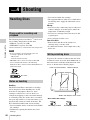
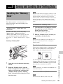
Handling Discs ........................................................................................... 68
Discs used for recording and playback ........................................... 68
Notes on handling ........................................................................... 68
Write-protecting discs..................................................................... 68
Loading and unloading a disc ......................................................... 69
Formatting a disc............................................................................. 70
Handling of discs when recording does not end normally (salvage
function).................................................................................... 70
Basic Procedure for Shooting ................................................................... 72
Playing back the recorded clip ........................................................ 74
Deleting the recorded clip ............................................................... 75
Advanced Operations for Shooting.......................................................... 76

Table of Contents
8
Recording essence marks ................................................................ 76
Setting the thumbnail image at recording time ............................... 76
Starting a shoot with a few seconds of pre-stored picture data (Picture
Cache function)......................................................................... 76
Retaking the most recent clip.......................................................... 78
Assigning user-defined clip titles automatically............................. 78
Assigning user-defined names to clips and clip lists ...................... 81
Chapter 5 : Operations in GUI Screens
Overview..................................................................................................... 84
Switching between GUI screens ..................................................... 84
Information and controls in thumbnail screens............................... 85
Displaying menus............................................................................ 89
GUI screen operations..................................................................... 91
Thumbnail Operations .............................................................................. 92
Selecting thumbnails ....................................................................... 92
Searching with thumbnails.............................................................. 92
Playing the scene you have found................................................... 94
Selecting the information displayed on thumbnails........................ 94
Changing clip index pictures........................................................... 95
Checking clip properties ................................................................. 96
Locking (write-protecting) clips ..................................................... 96
Deleting clips .................................................................................. 97
Scene Selection (Clip List Editing)........................................................... 98
What is scene selection?.................................................................. 98
Creating and editing clip lists.......................................................... 99
Managing clip lists ........................................................................ 104
Disc Operations........................................................................................ 105
Checking disc properties............................................................... 105
Formatting discs............................................................................ 105
Shortcut List............................................................................................. 107
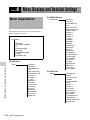
Chapter 6 : Menu Displays and Detailed Settings
Menu Organization.................................................................................. 108
TOP menu and top-level menus.................................................... 109
Menu List.................................................................................................. 111
OPERATION menu ...................................................................... 111
PAINT menu................................................................................. 117
MAINTENANCE menu................................................................ 123
FILE menu .................................................................................... 134

Table of Contents
9
DIAGNOSIS menu ....................................................................... 138
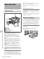
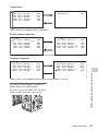
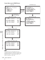
Menu Operations ..................................................................................... 140
Displaying menus.......................................................................... 140
Basic menu operations .................................................................. 140
Using the USER menu (example menu operation)....................... 143
Editing the USER menu................................................................ 144
Resetting USER menu settings to the standard settings................ 147
Setting the Status Display on the Viewfinder Screen and the LCD
Monitor............................................................................................... 148
Selecting the display items............................................................ 148
Change confirmation/adjustment progress messages.................... 149
Setting the marker display............................................................. 149
Setting the viewfinder ................................................................... 150
Recording shot data superimposed on the color bars.................... 151
Setting the shot ID......................................................................... 152
Displaying the status confirmation screens................................... 153
Adjustments and Settings From Menus ................................................ 154
Setting gain values for the GAIN selector positions..................... 154
Selecting the output signals........................................................... 155
Assigning functions to ASSIGN switches .................................... 155
Setting power saving functions..................................................... 157
Setting the color temperature manually ........................................ 158
Specifying an offset for the auto white balance setting ................ 158
Selecting the lens file .................................................................... 159
Setting the UMID data .................................................................. 159
Chapter 7 : Saving and Loading User Setting Data
Handling the “Memory Stick”................................................................ 161
Saving and Recalling User Files ............................................................. 162
Saving user menu data to the “Memory Stick”............................. 162
Loading saved data from a “Memory Stick”................................. 164
Returning the user file settings to the standard settings................ 165
Saving and Loading Scene Files ............................................................. 165
Saving a scene file......................................................................... 165
Loading scene files........................................................................ 167
Returning the scene file settings to the standard settings.............. 168
Jumping to a File-Related Menu Page When Inserting a “Memory Stick”
............................................................................................................. 168

Table of Contents
10
Chapter 8 : File Operations
Overview................................................................................................... 170
Directory structure ........................................................................ 170
File operation restrictions.............................................................. 170
File Operations in File Access Mode (for Windows) ............................ 174
Making FAM connections............................................................. 174
Operating on files.......................................................................... 175
Exiting file operations................................................................... 175
File Operations in File Access Mode (for Macintosh) .......................... 176
Making FAM connections............................................................. 176
Operating on files.......................................................................... 177
Exiting file operations................................................................... 177
FTP File Operations ................................................................................ 178
Making FTP connections .............................................................. 178
Command list ................................................................................ 179
Recording Continuous Timecode With FAM and FTP Connections . 183
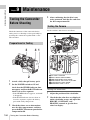
Chapter 9 : Maintenance
Testing the Camcorder Before Shooting ............................................... 184
Preparations for Testing ................................................................ 184
Testing the Camera ....................................................................... 184
Testing the VDR ........................................................................... 186
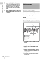
Maintenance ............................................................................................. 188
Cleaning the Viewfinder ............................................................... 188
Note About the Battery Terminal.................................................. 189
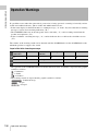
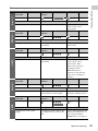
Operation Warnings................................................................................ 190
Appendix
Important Notes on Operation ............................................................... 196
Specifications............................................................................................ 198
General.......................................................................................... 198
Video camera section.................................................................... 198
Optical disc drive section.............................................................. 199
Supplied accessories...................................................................... 200
Recommended additional equipment............................................ 200
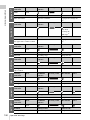
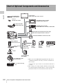
Chart of Optional Components and Accessories .................................. 202
Using PDZ-1 Proxy Browsing Software ................................................ 203

Table of Contents
11
Trademarks and Licenses ....................................................................... 203
MPEG-4 Visual Patent Portfolio License ..................................... 203
MPEG-2 Video Patent Portfolio License...................................... 203
About IJG (Independent JPEG Group) ......................................... 204
Character display software “iType”.............................................. 204
About a “Memory Stick” ........................................................................ 204
Index.......................................................................................................... 207

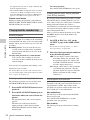
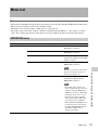
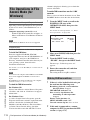
Foreword
12
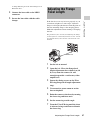
After purchasing this unit, before operating, it is
necessary to set the region of use and the frame
frequency.
(Unless this setting is made, the unit will not
operate.)
For details of these settings, see “Setting the Area of
Use” on page 38.
The supplied CD-ROM includes versions of the
Operation Manual for the PDW-700 in English,
Japanese, French, German, Italian, Spanish, and
Chinese in PDF format.
Preparations
The following program must be installed on your
computer in order to read the Operation Manual
contained on the CD-ROM.
• Adobe Reader Version 6.0 or higher
Memo
If Adobe Reader is not installed, you can download it
from the following URL:
http://www.adobe.com/
Adobe and Adobe Reader are trademarks of Adobe
Systems Incorporated the United States and/or other
countries.
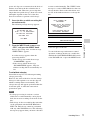
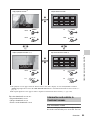
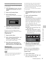
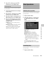
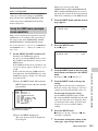
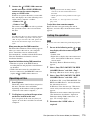
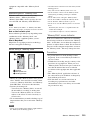
To read the CD-ROM manual
To read the Operation Manual contained on the
CD-ROM, do the following.
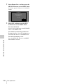
1 Insert the CD-ROM in your CD-ROM
drive.
A cover page appears automatically in your
browser.
If it does not appear automatically in the
browser, double-click on the index.htm file
on the CD-ROM.
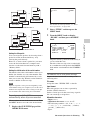
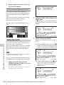
2 Select and click on the Operation
Manual that you want to read.
This opens the PDF file of the Operation
Manual.
Memo
The files may not be displayed properly, depending on
the version of Adobe Reader. In such a case, install the
latest version you can download from the URL
mentioned in “Preparations” above.
Note
If you have lost or damaged the CD-ROM, you can
purchase a new one to replace it. Contact a Sony service
representative.
Foreword
Before use
Using the CD-ROM manual

Features
13
Chapter 1 Overview
New
2
/
3
-inch full-HD “PowerHAD FX”
CCDs
• IT (Interline Transfer)
2
/
3
-inch progressive
image sensors with 2.2 million pixels, for full
HD resolution (1920 × 1080)
• Newly developed “PowerHAD FX” CCDs,
featuring a signal processing ASIC with 14-bit
A/D converters
These new image sensor technologies enable the
capture of very high-quality images, with F11
(59.94i) and F12 (50i) sensitivity and an SN ratio
of 59 dB.
1)
1) With noise suppression on (off value is 54 dB)
Noise suppression uses proprietary Sony signal
processing technology to suppress noise in high-
frequency regions.
Multi-format support for 1080/59.94i and
1080/50i
The unit support two system frequencies (59.94
Hz and 50 Hz), offering the flexibility needed for
worldwide HD recording.
Recording of more than 90 minutes of
high-quality video and audio data
• Signals captured by the full-HD (1920 × 1080)
image sensors are recorded in MPEG HD422
format
1)
for consistently high image quality.
2)
• The unit supports recording of four audio
channels
3)
sampled at 24 bits for high quality.
• Dual-layer Professional discs can record about
95 minutes of high-quality video and audio
data.
The generous recording times and the high-
quality of the recorded video and audio allow this
unit to meet the most stringent requirements of
production teams in a wide range of genres, from
news gathering through digital cinema and
program production.
1) The MPEG-2 422P@HL codec performs 4:2:2
sampling and records at a video bit rate of 50 Mbps.
2) Image compression uses the MPEG-2 Long GOP
system.
3) The PDW-HD1500 supports recording of up to eight
channels in MPEG HD422 format.
Rich selection of interfaces
• HDSDI and SDSDI output connectors: Allow
free combination of HDSDI and SDSDI signals.
Timecode and other text data can be
superimposed on signals from one of the two
interfaces.
• Composite signal output connector
• Gen-lock input connector: Enables
synchronized operation of multiple units, with
synchronization possible to either VBS or HD-
Y signals.
• Audio input connectors: Supports AES/EBU
signal input, in addition to microphone input,
+48 V microphone input, and line input.
• Timecode input and output connectors
• Network connector and i.LINK connector:
Enable transfer of MXF-format files. Material
recorded in the field can be transferred to a
computer for immediate cut editing with the
supplied PDZ-1 Proxy Browsing Software.
Features for improved performance
under various shooting conditions
• The popular Picture Cache function introduced
by the HDCAM and XDCAM HD series is
offered as a standard feature.
• Color temperature filters are composed of
electronic circuits, allowing smooth and
instantaneous switching – an important
advantage in ENG
1)
– and linked operation
with ND filters. Further, absolute color
temperature settings can be obtained without
being effected by white balance settings.
• New noise suppression circuits offer improved
performance under difficult evening or
nighttime shooting conditions.
1) ENG: Electronic News Gathering
Chapter1 Overview
Features

Locations and Functions of Parts and Controls
14
Chapter 1 Overview
Supports new digital wireless
microphone system
The new digital wireless microphone system
offers high-quality, superior resistance to noise,
and simultaneous multi-channel operation.
Installation of the DWR-S01D Digital Wireless
Receiver
1)
enables simultaneous reception of two
channels.
1) These products are not available in countries where
they are prohibited by radio frequency regulations.
Note
When you use the DWR-S01D Digital Wireless
Receiver in combination with this camcorder, you need
to check both of their versions.
Consult a Sony representative for information about
these versions.
3.5-inch color LCD monitor
The 3.5-inch color LCD monitor displays audio
meters, menu, and thumbnails of clips stored on
disc.
Inherits unique features of XDCAM series
The unit inherits the workflow features of the
XDCAM series, including thumbnail display and
metadata management, and improves them by
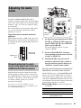
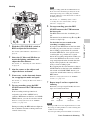
introducing an improved man-machine interface.
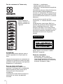
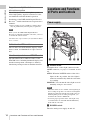
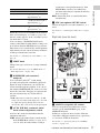
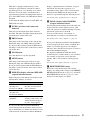
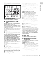
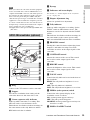
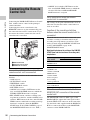
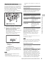
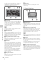
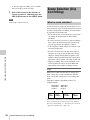
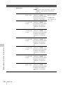
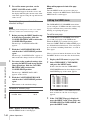
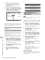
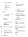
a LIGHT switch
Determines how a video light connected to the
LIGHT connector (see page 15) is turned on and
off.
AUTO: When the POWER switch of the video
light is in the on position, the video light is
turned on automatically while the camcorder
is recording.
MANUAL: You can turn the video light on or off
manually, using its own switch.
Notes
• When this switch is set to AUTO, at the beginning of
the recording, the picture is recorded even though the
lighting may fluctuate until the video light comes on.
If the beginning of the recording is important, you
should set this switch to MANUAL.
• To ensure proper operation of the video light, Sony
recommends the use of the BP-GL95/L80S Battery
Pack with the camcorder.
b POWER switch
Turns the main power supply on and off.
Locations and Functions
of Parts and Controls
Power supply
231 54

Locations and Functions of Parts and Controls
15
Chapter 1 Overview
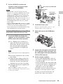
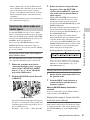
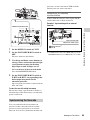
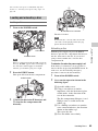
c DC IN (DC power input) connector
(XLR type, 4-pin, male)
To operate the camcorder from an AC power
supply, connect an optional DC power cord to this
terminal and then connect the cord to the DC
output terminal of the BC-L70, BC-M150, or
another battery charger.
d DC OUT 12V (DC power output)
connector (4-pin, female)
Supplies power for a WRR-860A/861/862 UHF
Synthesized Diversity Tuner (not supplied)
(maximum 0.5 A).
Do not connect any equipment other than the
UHF synthesized diversity tuner.
e Battery attachment shoe
Attach a BP-GL95/GL65/L60S/L80S Battery
Pack. Alternatively, you can attach an AC-
DN2B/DN10 AC Adaptor to operate the
camcorder on AC power supply.
For details about how to attach the battery or AC
adaptor, see “Preparing a Power Supply” on page
33. For information about attaching a synthesized
tuner, see “Attaching a UHF portable tuner (for a
UHF wireless microphone system)” on page 44.
Note
For your safety, and to ensure proper operation of the
camcorder, Sony recommends the use of the following
battery packs: BP-GL95, BP-GL65, BP-L60S, and BP-
L80S.
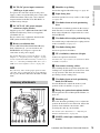
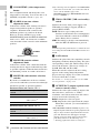
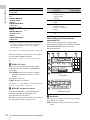
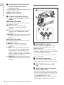
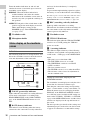
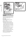
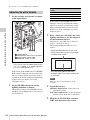
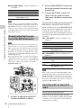
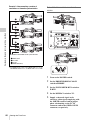
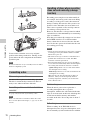
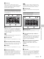
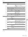
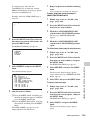
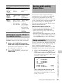
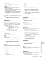
a Shoulder strap fitting
Attach the supplied shoulder strap (see page 48).
b Light fitting shoe
Attach an optional accessory such as a video light
(see page 48).
c Viewfinder front-to-back positioning
lever
To adjust the viewfinder position in the front-to-
back direction, loosen this lever and the LOCK
knob. After adjustment, retighten this lever and
the LOCK knob.
d Viewfinder left-to-right positioning ring
Loosen this ring to adjust the left-to-right position
of the viewfinder (see page 35).
e Viewfinder fitting shoe
Attach an optional viewfinder.
f VF (viewfinder) connector (20-pin)
Connect an optional viewfinder.
Consult a Sony representative for information about
available viewfinders.
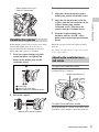
g Lens mount securing rubber
After locking the lens in position using the lens
locking lever, fit this rubber over the lower of the
two projections. This fixes the lens mount,
preventing it from coming loose.
h Viewfinder front-to-back positioning
knob (LOCK knob)
Loosen this knob to adjust the front-to-back
position of the viewfinder (see page 35).
i Fitting for optional microphone holder
Fit an optional CAC-12 Microphone Holder (see
page 43).
j Shoulder pad
Raise the shoulder pad fixing lever to adjust the
position in the front-to-rear direction. Adjust the
position for maximum convenience when
operating the unit on your shoulder.
For details of the adjustment, see “Adjusting the
Shoulder Pad Position” on page 49.
k LIGHT (video light) connector (2-pin,
female)
Accessory attachments
5674231
890qaqs qd qgqh qj
qk
qf

Locations and Functions of Parts and Controls
16
Chapter 1 Overview
A video light with a maximum power
consumption of 50 W, such as the Anton Bauer
Ultralight 2 or equivalent can be connected (see
page 48).
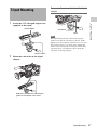
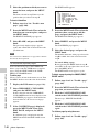
l Lens cable clamp
Clamp a lens cable.
m MIC IN (microphone input) (+48 V)
connector (XLR type, 5-pin, female)
Connect a stereo microphone to this connector.
The power (+48 V) is supplied via this connector.
n LENS connector (12-pin)
Connect a lens cable to this connector
Note
When connecting the lens cable to this connector,
power off this unit first.
o Tripod mount
When using the unit on a tripod, attach the tripod
adaptor (option).
p Lens mount (special bayonet mount)
Attach the lens.
Consult a Sony representative for information about
available lenses.
q Lens locking lever
After inserting the lens in the lens mount, rotate
the lens mount ring with this lever to lock the lens
in position.
After locking the lens, be sure to use the lens
mount securing rubber to prevent the lens from
becoming detached.
r Lens mount cap
Remove by pushing up the lens locking lever.
When no lens is mounted, keep this cap fitted for
protection from dust.
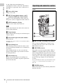
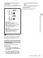
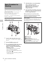
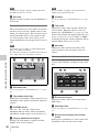
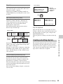
Front
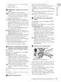
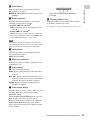
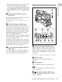
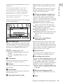
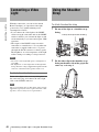
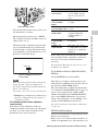
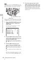
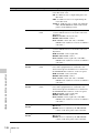
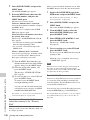
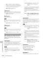
a REC START (recording start) button
Press to start recording. Press it again to stop
recording. The effect is the same as that of the
REC button on the lens.
b SHUTTER selector
Set to ON to use the electronic shutter. Flick to
SELECT to switch the shutter speed or shutter
mode setting within the range previously set with
the menu. When this switch is operated, the new
setting appears on the setting change/adjustment
progress message display area for about three
seconds.
For details about the shutter speed and shutter mode
settings, see “Setting the Electronic Shutter” on
page 56.
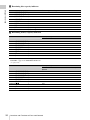
c FILTER selector
Selects from the four neutral density (ND) filters
built into this unit.
Operating and connectors section
2
1
7
5
6
3
4

Locations and Functions of Parts and Controls
17
Chapter 1 Overview
When this selector is used with the menu item for
filter selection display set to ON (see page 149),
the new setting appears on the viewfinder screen
for about three seconds.
You can change a MAINTENANCE menu
setting so that different white balance settings can
be stored for different FILTER selector positions.
This allows you to automatically obtain optimum
white balance for the current shooting conditions
in linkage with the filter selection.
For details, see “Adjusting the white balance” on
page 54.
d MENU knob
Changes the page selection or a setting within the
menu.
For details about how to use the MENU knob, see
“Menu Operations” on page 140.
e EARPHONE jack (monaural,
minijack)
You can monitor the E-E
1)
sound during
recording and playback sound during playback.
When an alarm is indicated, you can hear the
alarm sound through the earphone. You can use
this with the EARPHONE jack on the rear of the
unit at the same time. Plugging an earphone into
the jack automatically cuts off the built-in
speaker.
1) E-E: Abbreviation of “Electric-to-Electric”. In E-E
mode, video and audio signals input to the camcorder
are output after passing through internal electric
circuits only. This can be used to check input signals.
f AUTO W/B BAL (automatic white/
black balance adjustment) switch
Activates the automatic white/black balance
adjustment functions.
WHT: Adjusts the white balance automatically.
If the WHITE BAL switch (see page 19) is
set to A or B, the white balance setting is
stored in the corresponding memory. If the
WHITE BAL switch is set to PRST, the
automatic white balance adjustment function
does not operate.
BLK: Adjusts the black set and black balance
automatically.
g MIC (microphone) LEVEL control
Adjusts the input level of audio channels 1, 2, 3
and 4.
For details, see “Adjusting the Audio Level” on page
61.
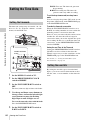
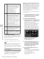
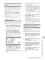
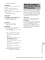
Right side (near the front)
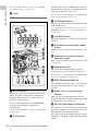
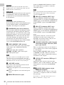
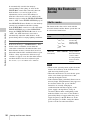
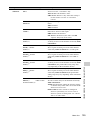
a ASSIGN (assignable) 1/2 switches
You can assign the desired functions to these
switches on the ASSIGNABLE page of the
OPERATION menu.
Nothing is assigned to these switches when the
camcorder is shipped from the factory (equivalent
to a selection of OFF in the menu).
For details, see “Assigning functions to ASSIGN
switches” on page 155.
Position number ND filter
1CLEAR
2
1
/
4
ND (attenuates light to
approximately
1
/
4
)
3
1
/
16
ND (attenuates light to
approximately
1
/
16
)
4
1
/
64
ND (attenuates light to
approximately
1
/
64
)
MENU
ON/
SEL
OFF
STATUS
CANCEL/PRST
ESCAPEON
OFF
5
6789
2341
qa qs0
qf
qd

Locations and Functions of Parts and Controls
18
Chapter 1 Overview
b COLOR TEMP. (color temperature)
button
Press to light the button and change the color
temperature for shooting. You can use this as an
ASSIGN (assignable) switch
(see page 155).
c ALARM (alarm tone volume
adjustment) knob
Controls the volume of the warning tone that is
output via the built-in speaker or optional
earphones. When the knob is turned to the
minimum position, no sound can be heard.
However, if in the AUDIO-1 page of the
MAINTENANCE menu the MIN ALARM VOL
item is set to “SET”, the alarm tone is audible
even when this volume control is at the minimum
position.
d MONITOR (monitor volume
adjustment) knob
Controls the volume of the sound other than the
warning tone that is output via the built-in speaker
or optional earphones. When the knob is turned to
the minimum position, no sound can be heard.
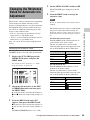
e MONITOR (audio monitor selection)
switches
By means of combinations of the two switches,
you can select audio that you want to hear through
the built-in speaker or optional earphones.
Position of down-side switch: CH-1/2
Position of down-side switch: CH-3/4
a) By connecting stereo headphones to the EARPHONE
jack on the rear of the unit, you can hear the audio in
stereo. (On the AUDIO-1 page of the
MAINTENANCE menu, HEADPHONE OUT must
be set to “STEREO”.)
f VDR SAVE/STBY (VDR save/standby)
switch
Switches the status of the power supply to the
VDR while recording is stopped (STOP) or
paused (REC PAUSE).
SAVE: The disc stops rotating and some
functions are disabled. Power consumption is
lower than when the camcorder is in STBY
mode. Battery life is extended.
STBY: Recording to the disc starts immediately
when the REC START button is pressed.
Note
An internal operating sound may be recorded at the start
of recording when the VDR SAVE/STBY switch is set to
SAVE.
g GAIN selector
Switches the gain of the video amplifier to match
the lighting conditions during shooting. The gains
corresponding to the L, M, and H settings can be
selected in the menu. (The factory settings are
L=0 dB, M=6 dB, and H=12 dB.)
When this switch is adjusted, the new setting
appears on the setting change/adjustment
progress message display area of the viewfinder
screen for about three seconds.
For details, see “Setting gain values for the GAIN
selector positions” on page 154.
h OUTPUT/DCC (output signal/dynamic
contrast control) switch
Switches the video signal, which is output to the
video disc drive (referred to as “VDR”),
viewfinder, and video monitor from the camera
section, between the following two.
BARS: Outputs the color bar signal.
CAM: Outputs the video signal from the camera.
When this is selected, you can switch DCC
1)
on and off.
1) DCC (Dynamic Contrast Control): Against a very
bright background with the iris opening adjusted to the
subject, objects in the background will be lost in the
glare. The DCC function will suppress the high
intensity and restore much of the lost detail and is
particularly effective in the following cases.
• Shooting people in the shade on a sunny day
Position of up-side
switch
Audio output
CH-1/CH-3 Channel 1 audio
MIX Channels 1 and 2 mixed
audio (stereo)
a)
CH-2/CH-4 Channel 2 audio
Position of up-side
switch
Audio output
CH-1/CH-3 Channel 3 audio
MIX Channels 3 and 4 mixed
audio (stereo)
a)
CH-2/CH-4 Channel 4 audio
ALARM
Minimum Maximum

Locations and Functions of Parts and Controls
19
Chapter 1 Overview
• Shooting a subject indoors, against a background
through a window
• Any high contrast scene
i WHITE BAL (white balance memory)
switch
Controls adjustment of the white balance.
PRST: Adjusts the color temperature to the preset
value (the factory default setting: 3200K).
Use this setting when you have no time to
adjust the white balance.
A or B: Recall the white balance adjustment
settings already stored in A or B. Flick the
AUTO W/B BAL switch (see page 17) on the
WHT side, to automatically adjust the white
balance, and save the adjustment settings in
memory A or memory B.
You can use the AUTO W/B BAL switch
even when ATW
1)
is in use.
B (ATW): When this switch is set to B and
WHITE SWITCH <B> is set to ATW on the
WHITE SETTING page of the
MAINTENANCE menu, ATW is activated.
When this switch is adjusted, the new setting
appears on the setting change/adjustment
progress message display area of the viewfinder
screen for about three seconds.
1) ATW (Auto Tracing White Balance): The white
balance of the picture being shot is adjusted
automatically for varying lighting conditions.
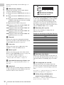
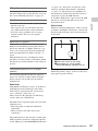
j STATUS ON/SEL/OFF (menu display
on/page selection/display off) switch
To enable this switch, set the MENU ON/OFF
switch to OFF.
Closing the cover automatically sets the MENU
ON/OFF switch to OFF.
ON/SEL: Each time this switch is pushed
upward, a window to confirm the menu
settings and status of the camcorder appears
on the viewfinder screen. The window
consists of four pages, which are switched
each time the switch is pushed upward. Each
page is displayed for about 10 seconds.
OFF: To clear the page immediately after
display, push this switch down to the OFF
position.
You can select the pages to be displayed on the
menu.
For details, see “Displaying the status confirmation
screens” on page 153.
k MENU ON/OFF switch
To use this switch, open the cover.
This switch is used to display the menu on the
viewfinder screen or the test signal screen.
Closing the cover automatically sets this switch to
OFF.
ON: Displays the menu on the viewfinder screen
or the test signal screen.
OFF: Removes the menu from the viewfinder
screen or the test signal screen.
l CANCEL/PRST (preset)/ESCAPE
switch
To enable this switch, set the MENU ON/OFF
switch to ON.
Closing the cover automatically sets the MENU
ON/OFF switch to OFF.
CANCEL/PRST: Flicking this switch up to this
position displays the message to confirm
whether the previous settings are cancelled or
settings are reset to their initial values,
depending on the menu operating condition.
Flicking this switch up to this position again
cancels the previous settings or resets the
settings to their initial values.
ESCAPE: Use this switch when the menu page,
which has a hierarchical structure, is opened.
Each time the switch is flicked to this
position, the page returns to one stage higher
in the hierarchy.
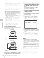
m “Memory Stick” compartment
Open the lid of the menu operating section, and
insert a “Memory Stick”, with the notch facing
downward, in the direction shown by the arrow,
so that it clicks into place.
To remove a “Memory Stick”, first press it in to
release the lock, then withdraw.
The “Memory Stick” access indicator lights in
green when a “Memory Stick” is loaded, and
lights in red when the “Memory Stick” is being
accessed for reading or writing.
“Memory Stick” Access indicator
Label

Locations and Functions of Parts and Controls
20
Chapter 1 Overview
For details about “Memory Stick”, see “Handling
the “Memory Stick”” on page 161.
n Cover
Right side (near the rear)
a Built-in speaker
The speaker can be used to monitor E-E sound
during recording, and playback sound during
playback. The speaker also sounds alarms to
reinforce visual warnings.
If you connect earphones to the EARPHONE
jack, the speaker output is suppressed
automatically.
For details about alarms, see “Operation Warnings”
on page 190.
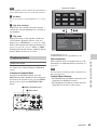
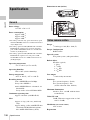
b LCD monitor
Displays camera video, VDR-related warnings,
remaining battery capacity, remaining disc space,
audio levels, time data, and so on.
For details, see “Status Display on the LCD monitor
and monochrome LCD” on page 22.
c WARNING indicator
Lights up or flashes when an abnormality occurs
in the VDR section.
For details about the meaning of the states of the
WARNING indicator, see ““Operation Warnings”
on page 190.
d ACCESS indicator
This lights when data is written to or read from
the disc.
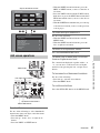
e Protection cover of the audio control
section
Open to access the audio control section (see page
25).
f Protection cover of the GUI screen
operations section
Open to access the GUI screen operations section
(see page 25).
g Monochrome LCD
This shows the remaining battery capacity,
remaining disc capacity, time data, and so on.
For details, see “Status Display on the LCD monitor
and monochrome LCD” on page 22.
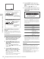
h EJECT button and indicator
Press this button to insert a disc or eject the disc.
The indicator flashes while the disc is being
ejected.
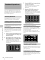
i F REV (fast reverse) button and
indicator
This plays back at high speed in the reverse
direction. The indicator lights during high-speed
playback in the reverse direction.
j PLAY/PAUSE button and indicator
Press this button to view play back video images
using the viewfinder screen or the LCD monitor.
The indicator lights during playback.
Press this button again during playback to pause,
outputting a still image. At this time the indicator
flashes.
F REV
PREV
Z
PLAY/PAUSE
STOP NEXT
F FWD
m
.
NX
x>
M
EJECT
BRIGHTDISPLAYRESETHOLDDISP SEL
COUNTER TC U-BITEXPAND CHAPTER RETURN
2
3
4
5
6
7
1
qs qd qf
8 9 q; qa
qg qh qj qk ql
Page is loading ...
Page is loading ...
Page is loading ...
Page is loading ...
Page is loading ...
Page is loading ...
Page is loading ...
Page is loading ...
Page is loading ...
Page is loading ...
Page is loading ...
Page is loading ...
Page is loading ...
Page is loading ...
Page is loading ...
Page is loading ...
Page is loading ...
Page is loading ...
Page is loading ...
Page is loading ...
Page is loading ...
Page is loading ...
Page is loading ...
Page is loading ...
Page is loading ...
Page is loading ...
Page is loading ...
Page is loading ...
Page is loading ...
Page is loading ...
Page is loading ...
Page is loading ...
Page is loading ...
Page is loading ...
Page is loading ...
Page is loading ...
Page is loading ...
Page is loading ...
Page is loading ...
Page is loading ...
Page is loading ...
Page is loading ...
Page is loading ...
Page is loading ...
Page is loading ...
Page is loading ...
Page is loading ...
Page is loading ...
Page is loading ...
Page is loading ...
Page is loading ...
Page is loading ...
Page is loading ...
Page is loading ...
Page is loading ...
Page is loading ...
Page is loading ...
Page is loading ...
Page is loading ...
Page is loading ...
Page is loading ...
Page is loading ...
Page is loading ...
Page is loading ...
Page is loading ...
Page is loading ...
Page is loading ...
Page is loading ...
Page is loading ...
Page is loading ...
Page is loading ...
Page is loading ...
Page is loading ...
Page is loading ...
Page is loading ...
Page is loading ...
Page is loading ...
Page is loading ...
Page is loading ...
Page is loading ...
Page is loading ...
Page is loading ...
Page is loading ...
Page is loading ...
Page is loading ...
Page is loading ...
Page is loading ...
Page is loading ...
Page is loading ...
Page is loading ...
Page is loading ...
Page is loading ...
Page is loading ...
Page is loading ...
Page is loading ...
Page is loading ...
Page is loading ...
Page is loading ...
Page is loading ...
Page is loading ...
Page is loading ...
Page is loading ...
Page is loading ...
Page is loading ...
Page is loading ...
Page is loading ...
Page is loading ...
Page is loading ...
Page is loading ...
Page is loading ...
Page is loading ...
Page is loading ...
Page is loading ...
Page is loading ...
Page is loading ...
Page is loading ...
Page is loading ...
Page is loading ...
Page is loading ...
Page is loading ...
Page is loading ...
Page is loading ...
Page is loading ...
Page is loading ...
Page is loading ...
Page is loading ...
Page is loading ...
Page is loading ...
Page is loading ...
Page is loading ...
Page is loading ...
Page is loading ...
Page is loading ...
Page is loading ...
Page is loading ...
Page is loading ...
Page is loading ...
Page is loading ...
Page is loading ...
Page is loading ...
Page is loading ...
Page is loading ...
Page is loading ...
Page is loading ...
Page is loading ...
Page is loading ...
Page is loading ...
Page is loading ...
Page is loading ...
Page is loading ...
Page is loading ...
Page is loading ...
Page is loading ...
Page is loading ...
Page is loading ...
Page is loading ...
Page is loading ...
Page is loading ...
Page is loading ...
Page is loading ...
Page is loading ...
Page is loading ...
Page is loading ...
Page is loading ...
Page is loading ...
Page is loading ...
Page is loading ...
Page is loading ...
Page is loading ...
Page is loading ...
Page is loading ...
Page is loading ...
Page is loading ...
Page is loading ...
Page is loading ...
Page is loading ...
Page is loading ...
Page is loading ...
Page is loading ...
Page is loading ...
Page is loading ...
Page is loading ...
Page is loading ...
Page is loading ...
Page is loading ...
Page is loading ...
Page is loading ...
Page is loading ...
Page is loading ...
Page is loading ...
Page is loading ...
Page is loading ...
Page is loading ...
-
 1
1
-
 2
2
-
 3
3
-
 4
4
-
 5
5
-
 6
6
-
 7
7
-
 8
8
-
 9
9
-
 10
10
-
 11
11
-
 12
12
-
 13
13
-
 14
14
-
 15
15
-
 16
16
-
 17
17
-
 18
18
-
 19
19
-
 20
20
-
 21
21
-
 22
22
-
 23
23
-
 24
24
-
 25
25
-
 26
26
-
 27
27
-
 28
28
-
 29
29
-
 30
30
-
 31
31
-
 32
32
-
 33
33
-
 34
34
-
 35
35
-
 36
36
-
 37
37
-
 38
38
-
 39
39
-
 40
40
-
 41
41
-
 42
42
-
 43
43
-
 44
44
-
 45
45
-
 46
46
-
 47
47
-
 48
48
-
 49
49
-
 50
50
-
 51
51
-
 52
52
-
 53
53
-
 54
54
-
 55
55
-
 56
56
-
 57
57
-
 58
58
-
 59
59
-
 60
60
-
 61
61
-
 62
62
-
 63
63
-
 64
64
-
 65
65
-
 66
66
-
 67
67
-
 68
68
-
 69
69
-
 70
70
-
 71
71
-
 72
72
-
 73
73
-
 74
74
-
 75
75
-
 76
76
-
 77
77
-
 78
78
-
 79
79
-
 80
80
-
 81
81
-
 82
82
-
 83
83
-
 84
84
-
 85
85
-
 86
86
-
 87
87
-
 88
88
-
 89
89
-
 90
90
-
 91
91
-
 92
92
-
 93
93
-
 94
94
-
 95
95
-
 96
96
-
 97
97
-
 98
98
-
 99
99
-
 100
100
-
 101
101
-
 102
102
-
 103
103
-
 104
104
-
 105
105
-
 106
106
-
 107
107
-
 108
108
-
 109
109
-
 110
110
-
 111
111
-
 112
112
-
 113
113
-
 114
114
-
 115
115
-
 116
116
-
 117
117
-
 118
118
-
 119
119
-
 120
120
-
 121
121
-
 122
122
-
 123
123
-
 124
124
-
 125
125
-
 126
126
-
 127
127
-
 128
128
-
 129
129
-
 130
130
-
 131
131
-
 132
132
-
 133
133
-
 134
134
-
 135
135
-
 136
136
-
 137
137
-
 138
138
-
 139
139
-
 140
140
-
 141
141
-
 142
142
-
 143
143
-
 144
144
-
 145
145
-
 146
146
-
 147
147
-
 148
148
-
 149
149
-
 150
150
-
 151
151
-
 152
152
-
 153
153
-
 154
154
-
 155
155
-
 156
156
-
 157
157
-
 158
158
-
 159
159
-
 160
160
-
 161
161
-
 162
162
-
 163
163
-
 164
164
-
 165
165
-
 166
166
-
 167
167
-
 168
168
-
 169
169
-
 170
170
-
 171
171
-
 172
172
-
 173
173
-
 174
174
-
 175
175
-
 176
176
-
 177
177
-
 178
178
-
 179
179
-
 180
180
-
 181
181
-
 182
182
-
 183
183
-
 184
184
-
 185
185
-
 186
186
-
 187
187
-
 188
188
-
 189
189
-
 190
190
-
 191
191
-
 192
192
-
 193
193
-
 194
194
-
 195
195
-
 196
196
-
 197
197
-
 198
198
-
 199
199
-
 200
200
-
 201
201
-
 202
202
-
 203
203
-
 204
204
-
 205
205
-
 206
206
-
 207
207
-
 208
208
-
 209
209
-
 210
210
-
 211
211
-
 212
212
-
 213
213


Sony XDCAM PDW-700 Operating instructions
- Category
- Camcorders
- Type
- Operating instructions
Ask a question and I''ll find the answer in the document
Finding information in a document is now easier with AI
Related papers
Other documents
-
Sony Ericsson PDW-530P User manual
-
Panasonic AJ-PD900W User manual
-
PSC Balanced Distribution Amp User manual
-
Builders Edge 050010212000 Installation guide
-
 Enabling Devices 7075W User manual
-
Hitachi HV-C20M Operating instructions
-
Havis C-FAM-301 User manual
-
-
-
