
Document Number: 321321-001
Intel® Xeon® Processor 5500 Series
Datasheet, Volume 1
March 2009

2 Intel
®
Xeon
®
Processor 5500 Series Datasheet, Volume 1
INFORMATION IN THIS DOCUMENT IS PROVIDED IN CONNECTION WITH INTEL® PRODUCTS. NO LICENSE, EXPRESS OR IMPLIED,
BY ESTOPPEL OR OTHERWISE, TO ANY INTELLECTUAL PROPERTY RIGHTS IS GRANTED BY THIS DOCUMENT. EXCEPT AS
PROVIDED IN INTEL'S TERMS AND CONDITIONS OF SALE FOR SUCH PRODUCTS, INTEL ASSUMES NO LIABILITY WHATSOEVER,
AND INTEL DISCLAIMS ANY EXPRESS OR IMPLIED WARRANTY, RELATING TO SALE AND/OR USE OF INTEL PRODUCTS INCLUDING
LIABILITY OR WARRANTIES RELATING TO FITNESS FOR A PARTICULAR PURPOSE, MERCHANTABILITY, OR INFRINGEMENT OF ANY
PATENT, COPYRIGHT OR OTHER INTELLECTUAL PROPERTY RIGHT. Intel products are not intended for use in medical, life saving, or
life sustaining applications.
Intel may make changes to specifications and product descriptions at any time, without notice.
Designers must not rely on the absence or characteristics of any features or instructions marked “reserved” or “undefined.” Intel
reserves these for future definition and shall have no responsibility whatsoever for conflicts or incompatibilities arising from future
changes to them.
The Intel® Xeon® Processor 5500 Series may contain design defects or errors known as errata which may cause the product to
deviate from published specifications.Current characterized errata are available on request.
Intel processor numbers are not a measure of performance. Processor numbers differentiate features within each processor family,
not across different processor families. See http://www.intel.com/products/processor_number for details. Over time processor
numbers will increment based on changes in clock, speed, cache, FSB, or other features, and increments are not intended to
represent proportional or quantitative increases in any particular feature. Current roadmap processor number progression is not
necessarily representative of future roadmaps. See www.intel.com/products/processor_number for details.
Hyper-Threading Technology requires a computer system with a processor supporting HT Technology and an HT Technology-
enabled chipset, BIOS and operating system. Performance will vary depending on the specific hardware and software you use. For
more information including details on which processors support HT Technology, see
http://www.intel.com/products/ht/hyperthreading_more.htm
Enabling Execute Disable Bit functionality requires a PC with a processor with Execute Disable Bit capability and a supporting
operating system. Check with your PC manufacturer on whether your system delivers Execute Disable Bit functionality.
64-bit computing on Intel architecture requires a computer system with a processor, chipset, BIOS, operating system, device
drivers and applications enabled for Intel® 64 architecture. Performance will vary depending on your hardware and software
configurations. Consult with your system vendor for more information.
Intel® Virtualization Technology requires a computer system with an enabled Intel® processor, BIOS, virtual machine monitor
(VMM) and, for some uses, certain computer system software enabled for it. Functionality, performance or other benefits will vary
depending on hardware and software configurations and may require a BIOS update. Software applications may not be compatible
with all operating systems. Please check with your application vendor.
Intel® Turbo Boost Technology requires a PC with a processor with Intel Turbo Boost Technology capability. Intel Turbo Boost
Technology performance varies depending on hardware, software and overall system configuration. Check with your PC
manufacturer on whether your system delivers Intel Turbo Boost Technology. For more information, see www.intel.com.
Enhanced Intel SpeedStep® Technology. See the http://processorfinder.intel.com or contact your Intel representative for more
information.
Contact your local Intel sales office or your distributor to obtain the latest specifications and before placing your product order.
I
2
C is a two-wire communications bus/protocol developed by Philips. SMBus is a subset of the I
2
C bus/protocol and was developed
by Intel. Implementations of the I
2
C bus/protocol may require licenses from various entities, including Philips Electronics N.V. and
North American Philips Corporation.
Intel, Xeon, Enhanced Intel SpeedStep Technology, and the Intel logo are trademarks of Intel Corporation in the United States and
other countries.
*Other brands and names are the property of their respective owners.
Copyright © 2009, Intel Corporation.

Intel
®
Xeon
®
Processor 5500 Series Datasheet, Volume 1 3
Contents
1Introduction..............................................................................................................9
1.1 Terminology .....................................................................................................10
1.2 References .......................................................................................................12
2 Intel® Xeon® Processors 5500 Series Electrical Specifications ...............................13
2.1 Processor Signaling ...........................................................................................13
2.1.1 Intel QuickPath Interconnect....................................................................13
2.1.2 DDR3 Signal Groups ...............................................................................13
2.1.3 Platform Environmental Control Interface (PECI) ........................................14
2.1.4 Processor Sideband Signals .....................................................................14
2.1.5 System Reference Clock..........................................................................14
2.1.6 Test Access Port (TAP) Signals.................................................................15
2.1.7 Power / Other Signals.............................................................................15
2.1.8 Reserved or Unused Signals.....................................................................23
2.2 Signal Group Summary......................................................................................23
2.3 Mixing Processors..............................................................................................25
2.4 Flexible Motherboard Guidelines (FMB).................................................................26
2.5 Absolute Maximum and Minimum Ratings.............................................................26
2.6 Processor DC Specifications ................................................................................28
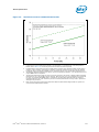
2.6.1 VCC Overshoot Specifications...................................................................31
2.6.2 Die Voltage Validation.............................................................................32
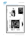
3 Package Mechanical Specifications ..........................................................................43
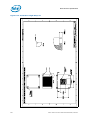
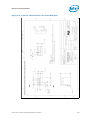
3.1 Package Mechanical Specifications.......................................................................43
3.1.1 Package Mechanical Drawing....................................................................44
3.1.2 Processor Component Keep-Out Zones......................................................47
3.1.3 Package Loading Specifications ................................................................47
3.1.4 Package Handling Guidelines....................................................................47
3.1.5 Package Insertion Specifications...............................................................47
3.1.6 Processor Mass Specification....................................................................48
3.1.7 Processor Materials.................................................................................48
3.1.8 Processor Markings.................................................................................48
3.1.9 Processor Land Coordinates.....................................................................48
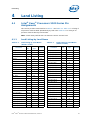
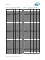
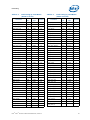
4Land Listing.............................................................................................................49
4.1 Intel® Xeon® Processors 5500 Series Pin Assignments..........................................49
4.1.1 Land Listing by Land Name......................................................................49
4.1.2 Land Listing by Land Number...................................................................67
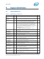
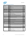
5 Signal Definitions ....................................................................................................85
5.1 Signal Definitions ..............................................................................................85
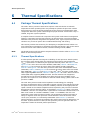
6 Thermal Specifications ............................................................................................89
6.1 Package Thermal Specifications...........................................................................89
6.1.1 Thermal Specifications............................................................................89
6.1.2 Thermal Metrology ............................................................................... 103
6.2 Processor Thermal Features.............................................................................. 104
6.2.1 Processor Temperature ......................................................................... 104
6.2.2 Adaptive Thermal Monitor...................................................................... 104
6.2.3 On-Demand Mode ................................................................................ 106
6.2.4 PROCHOT# Signal................................................................................ 106
6.2.5 THERMTRIP# Signal ............................................................................. 107
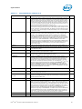
6.3 Platform Environment Control Interface (PECI).................................................... 107
6.3.1 PECI Client Capabilities ......................................................................... 108
6.3.2 Client Command Suite .......................................................................... 109

4 Intel
®
Xeon
®
Processor 5500 Series Datasheet, Volume 1
6.3.3 Multi-Domain Commands.......................................................................125
6.3.4 Client Responses ..................................................................................125
6.3.5 Originator Responses ............................................................................126
6.3.6 Temperature Data ................................................................................127
6.3.7 Client Management...............................................................................128
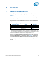
7Features................................................................................................................131
7.1 Power-On Configuration (POC)...........................................................................131
7.2 Clock Control and Low Power States...................................................................132
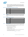
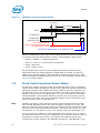
7.2.1 Thread and Core Power State Descriptions ...............................................133
7.2.2 Package Power State Descriptions...........................................................134
7.2.3 Intel® Xeon® Processor 5500 Series C-State Power Specifications..............135
7.3 Sleep States ...................................................................................................136
7.4 Intel
®
Turbo Boost Technology..........................................................................136
7.5 Enhanced Intel SpeedStep
®
Technology .............................................................136
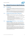
8 Boxed Processor Specifications..............................................................................137
8.1 Introduction....................................................................................................137
8.1.1 Available Boxed Thermal Solution Configurations ......................................137
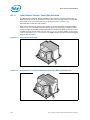
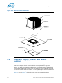
8.1.2 An Intel “Combo” Boxed Passive / Active Combination Heat Sink Solution.....137
8.1.3 Intel Boxed “Active” Heat Sink Solution ...................................................138
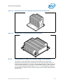
8.1.4 Intel Boxed 25.5mm Tall Passive Heat Sink Solution..................................139
8.2 Mechanical Specifications..................................................................................140
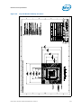
8.2.1 Boxed Processor Heat Sink Dimensions and Baseboard Keepout Zones ........140
8.2.2 Boxed Processor Retention Mechanism and Heat Sink
Support (URS)......................................................................................149
8.3 Fan Power Supply (“Combo” and “Active” Solution) ..............................................150
8.3.1 Boxed Processor Cooling Requirements....................................................151
8.4 Boxed Processor Contents.................................................................................153

Intel
®
Xeon
®
Processor 5500 Series Datasheet, Volume 1 5
Figures
2-1 Active ODT for a Differential Link Example............................................................13
2-2 Input Device Hysteresis .....................................................................................14
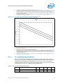
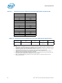
2-3 VCC Static and Transient Tolerance Loadlines1,2,3,4..............................................31
2-4 VCC Overshoot Example Waveform......................................................................32
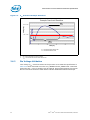
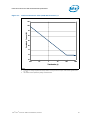
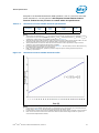
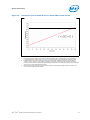
2-5 Load Current Versus Time (130W TDP Processor),2................................................33
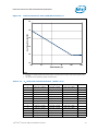
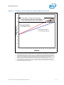
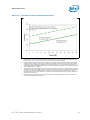
2-6 Load Current Versus Time (95W TDP Processor),2 .................................................34
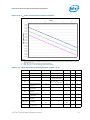
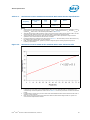
2-7 Load Current Versus Time (80W TDP Processor),2 .................................................35
2-8 Load Current Versus Time (60W TDP Processor),2 .................................................36
2-9 Load Current Versus Time (38W TDP Processor),2 .................................................37
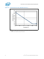
2-10 VTT Static and Transient Tolerance Loadlines........................................................39
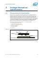
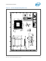
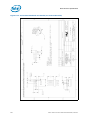
3-1 Processor Package Assembly Sketch ....................................................................43
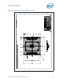
3-2 Processor Package Drawing (Sheet 1 of 2)............................................................45
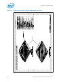
3-3 Processor Package Drawing (Sheet 2 of 2)............................................................46
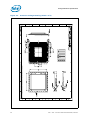
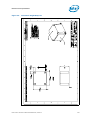
3-4 Processor Top-Side Markings ..............................................................................48
6-1 Intel Xeon Processor W5580 Thermal Profile ......................................................... 91
6-2 Intel Xeon Processor 5500 Series Advanced SKU Thermal Profile .............................93
6-3 Intel Xeon Processor 5500 Series Standard/Basic SKUs Thermal Profile .................... 95
6-4 Intel Xeon Processor 5500 Series Low Power SKU Thermal Profile............................ 97
6-5 Intel Xeon Processor L5518 Thermal Profile ..........................................................99
6-6 Intel Xeon Processor L5508 Thermal Profile ........................................................ 101
6-7 Case Temperature (TCASE) Measurement Location .............................................. 103
6-8 Frequency and Voltage Ordering........................................................................ 105
6-9 Ping()............................................................................................................ 109
6-10 Ping() Example ............................................................................................... 109
6-11 GetDIB()........................................................................................................ 110
6-12 Device Info Field Definition............................................................................... 110
6-13 Revision Number Definition............................................................................... 110
6-14 GetTemp() ..................................................................................................... 111
6-15 GetTemp() Example......................................................................................... 111
6-16 PCI Configuration Address................................................................................ 112
6-17 PCIConfigRd()................................................................................................. 113
6-18 PCIConfigWr() ................................................................................................ 115
6-19 Thermal Status Word....................................................................................... 117
6-20 Thermal Data Configuration Register.................................................................. 118
6-21 Machine Check Read MbxSend() Data Format...................................................... 118
6-22 ACPI T-state Throttling Control Read / Write Definition......................................... 120
6-23 MbxSend() Command Data Format.................................................................... 121
6-24 MbxSend() ..................................................................................................... 121
6-25 MbxGet() ....................................................................................................... 123
6-26 Temperature Sensor Data Format...................................................................... 127
6-27 PECI Power-up Timeline ................................................................................... 129
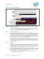
7-1 PROCHOT# POC Timing Requirements ............................................................... 132
7-2 Power States .................................................................................................. 133
8-1 Boxed Active Heat Sink.................................................................................... 138
8-2 Boxed Passive / Active Combination Heat Sink (With Removable Fan) .................... 138
8-3 Boxed Passive/Active Combination Heat Sink (with Fan Removed) ......................... 139
8-4 Intel Boxed 25.5 mm Tall Passive Heat Sink Solution ........................................... 139
8-5 Top Side Baseboard Keep-Out Zones ................................................................. 141
8-6 Top Side Baseboard Mounting-Hole Keep-Out Zones ............................................ 142
8-7 Bottom Side Baseboard Keep-Out Zones ............................................................ 143

6 Intel
®
Xeon
®
Processor 5500 Series Datasheet, Volume 1
8-8 Primary and Secondary Side 3D Height Restriction Zones......................................144
8-9 Volumetric Height Keep-Ins...............................................................................145
8-10 Volumetric Height Keep-Ins...............................................................................146
8-11 4-Pin Fan Cable Connector (For Active Heat Sink) ................................................147
8-12 4-Pin Base Baseboard Fan Header (For Active Heat Sink) ......................................148
8-13 Thermal Solution Installation.............................................................................150
8-14 Fan Cable Connector Pin Out For 4-Pin Active Thermal Solution..............................151
Tables
1-1 Intel Xeon Processor 5500 Series Feature Set Overview..........................................10
1-2 References........................................................................................................12
2-1 Processor Power Supply Voltages1 .......................................................................15
2-2 Voltage Identification Definition ...........................................................................17
2-3 Power-On Configuration (POC[7:0]) Decode..........................................................22
2-4 VTT Voltage Identification Definition.....................................................................23
2-5 Signal Groups ...................................................................................................23
2-6 Signals With On-Die Termination (ODT)................................................................25
2-7 Processor Absolute Minimum and Maximum Ratings ...............................................27
2-8 Voltage and Current Specifications.......................................................................28
2-9 VCC Static and Transient Tolerance.....................................................................30
2-10 VCC Overshoot Specifications..............................................................................31
2-11 VTT Static and Transient Tolerance .....................................................................37
2-12 DDR3 Signal Group DC Specifications ...................................................................39
2-13 PECI DC Electrical Limits.....................................................................................40
2-14 RESET# Signal DC Specifications .........................................................................41
2-15 TAP Signal Group DC Specifications......................................................................41
2-16 PWRGOOD Signal Group DC Specifications ............................................................41
2-17 Control Sideband Signal Group DC Specifications ...................................................42
3-1 Processor Loading Specifications..........................................................................47
3-2 Package Handling Guidelines...............................................................................47
3-3 Processor Materials............................................................................................48
4-1 Land Listing by Land Name .................................................................................49
4-2 Land Listing by Land Number ..............................................................................67
5-1 Signal Definitions...............................................................................................85
6-1 Intel Xeon Processor W5580 Thermal Specifications ...............................................91
6-2 Intel Xeon Processor W5580 Thermal Profile..........................................................92
6-3 Intel Xeon Processor 5500 Series Advanced SKU Thermal Specifications....................92
6-4 Intel Xeon Processor 5500 Series Advanced SKU Thermal Profile A...........................94
6-5 Intel Xeon Processor 5500 Series Advanced SKU Thermal Profile B...........................94
6-6 Intel Xeon Processor 5500 Series Standard/Basic SKUs Thermal Specifications...........95
6-7 Intel Xeon Processor 5500 Series Standard/Basic SKUs Thermal Profile.....................96
6-8 Intel Xeon Processor 5500 Series Low Power SKU Thermal Specifications ..................96
6-9 Intel Xeon Processor 5500 Series Low Power SKU Thermal Profile ............................98
6-10 Intel Xeon Processor L5518 Thermal Specifications.................................................98
6-11 Intel Xeon Processor L5518 Thermal Profile.........................................................100
6-12 Intel Xeon Processor L5508 Thermal Specifications...............................................100
6-13 Intel Xeon Processor L5508 Thermal Profile.........................................................102
6-14 Summary of Processor-specific PECI Commands ..................................................108
6-15 GetTemp() Response Definition .........................................................................112

Intel
®
Xeon
®
Processor 5500 Series Datasheet, Volume 1 7
6-16 PCIConfigRd() Response Definition .................................................................... 113
6-17 PCIConfigWr() Device/Function Support ............................................................. 114
6-18 PCIConfigWr() Response Definition.................................................................... 115
6-19 Mailbox Command Summary ............................................................................ 116
6-20 Counter Definition ........................................................................................... 117
6-21 Machine Check Bank Definitions ........................................................................ 119
6-22 ACPI T-state Duty Cycle Definition..................................................................... 120
6-23 MbxSend() Response Definition......................................................................... 122
6-24 MbxGet() Response Definition........................................................................... 123
6-25 Domain ID Definition ....................................................................................... 125
6-26 Multi-Domain Command Code Reference ............................................................ 125
6-27 Completion Code Pass/Fail Mask........................................................................ 125
6-28 Device Specific Completion Code (CC) Definition.................................................. 126
6-29 Originator Response Guidelines......................................................................... 126
6-30 Error Codes and Descriptions............................................................................ 128
6-31 PECI Client Response During Power-Up (During ‘Data Not Ready’) ......................... 128
6-32 Power Impact of PECI Commands versus C-states ............................................... 130
6-33 PECI Client Response During S1........................................................................ 130
7-1 Power On Configuration Signal Options............................................................... 131
7-2 Coordination of Thread Power States at the Core Level......................................... 133
7-3 Processor C-State Power Specifications .............................................................. 135
7-4 Processor S-States .......................................................................................... 136
8-1 PWM Fan Frequency Specifications For 4-Pin Active Thermal Solution ..................... 151
8-2 Fan Specifications For 4-Pin Active Thermal Solution............................................ 151
8-3 Fan Cable Connector Pin Out for 4-Pin Active Thermal Solution.............................. 151

8 Intel
®
Xeon
®
Processor 5500 Series Datasheet, Volume 1
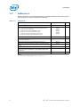
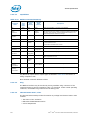
Revision History
§
Document
Number
Revision
Number
Description Date
321321 001 • Initial release March 2009

Intel
®
Xeon
®
Processor 5500 Series Datasheet, Volume 1 9
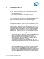
Introduction
1 Introduction
The Intel
®
Xeon
®
Processor 5500 Series is the first-generation server/workstation
multi-core processor to implement key new technologies:
• Integrated Memory Controller
• Point-to-point link interface based on Intel
®
QuickPath Technology
The processor is optimized for performance with the power efficiencies of a low-power
microarchitecture to enable smaller, quieter systems.
This document provides DC electrical specifications, differential signaling specifications,
pinout and signal definitions, package mechanical specifications and thermal
requirements, and additional features pertinent to implementation and operation of the
processor. For information on register descriptions, refer to the Intel
®
Xeon
®
Processor
5500 Series Datasheet, Volume 2
Intel Xeon Processor 5500 Series are multi-core processors, based on 45 nm process
technology. The processor family features a range of thermal design power (TDP)
envelopes from 38W TDP up to 130W TDP. These processors feature two Intel
QuickPath Interconnect point-to-point links capable of up to 6.4 GT/s, up to 8 MB of
shared cache, and an Integrated Memory Controller. The processors support all the
existing Streaming SIMD Extensions 2 (SSE2), Streaming SIMD Extensions 3 (SSE3)
and Streaming SIMD Extensions 4 (SSE4). The processors support several Advanced
Technologies: Execute Disable Bit, Intel
®
64 Technology, Enhanced Intel SpeedStep
®
Technology, Intel
®
Virtualization Technology (Intel
®
VT), Intel
®
Hyper-Threading
Technology (Intel
®
HT Technology), and Intel
®
Turbo Boost Technology (Intel
®
TBT).
The Intel Xeon Processor 5500 Series family supports multiple platform segments.
• 2-Socket Workstation Platforms support Intel
®
Xeon
®
Processor W5580, a 130W
Thermal Design Power (TDP) SKU. These platforms provide optimal overall
performance and reliability, in addition to high-end graphics support. Note, specific
platform usage conditions apply when implementing these processors.
• 2-Socket High Performance Server and High Performance Computing (HPC)
Platforms support Intel Xeon Processor 5500 Series Advanced SKU (95W TDP).
These platforms provide optimal overall performance.
• 2-Socket Volume Server Platforms support Intel Xeon Processor 5500 Series
Standard/Basic SKUs (80W TDP). These platforms provide optimal performance per
watt for rack-optimized platforms.
• Ultra Dense Platforms implement Intel Xeon Processor 5500 Series Low Power SKU
(60W TDP). These processors are intended for dual-processor server blades and
embedded servers.
•Intel
®
Xeon
®
Processor L5518 with 60W TDP and elevated case temperatures. The
elevated case temperatures are intended to meet the short-term thermal profile
requirements of NEBS Level 3. These 2-Socket processors are ideal for thermally-
constrained form factors in embedded servers, comms and storage markets.
•Intel
®
Xeon
®
Processor L5508 with 38W TDP and elevated case temperatures. The
elevated case temperatures are intended to meet the short-term thermal profile
requirements of NEBS Level 3. These 2-Socket processors are ideal for thermally-
constrained form factors in embedded servers, comms and storage markets.

Introduction
10 Intel
®
Xeon
®
Processor 5500 Series Datasheet, Volume 1
• 1-Socket Workstation Platforms support Intel Xeon Processor 5500 Series SKUs.
These platforms enable a wide range of options for either the performance, power,
or cost sensitive customer.
Note: All references to “chipset” in this document pertain to the Intel
®
5520 chipset and
Intel
®
5500 chipset, unless specifically stated otherwise.
1.1 Terminology
A ‘#’ symbol after a signal name refers to an active low signal, indicating a signal is in
the active state when driven to a low level. For example, when RESET# is low, a reset
has been requested.
A ‘_N’ and ‘_P’ after a signal name refers to a differential pair.
Commonly used terms are explained here for clarification:
• 1366-land FC-LGA package — The Intel Xeon Processor 5500 Series is available
in a Flip-Chip Land Grid Array (FC-LGA) package, consisting of processor mounted
on a land grid array substrate with an integrated heat spreader (IHS).
• DDR3 — Double Data Rate 3 synchronous dynamic random access memory
(SDRAM) is the name of the new DDR memory standard that is being developed as
the successor to DDR2 SDRAM.
• Enhanced Intel SpeedStep Technology — Enhanced Intel SpeedStep
Technology allows the operating system to reduce power consumption when
performance is not needed.
• Intel Turbo Boost Technology — Intel Turbo Boost Technology is a way to
automatically run the processor core faster than the marked frequency if the part is
operating under power, temperature, and current specifications limits of the
Thermal Design Power (TDP). This results in increased performance of both single
and multi-threaded applications.
• Execute Disable Bit — Execute Disable allows memory to be marked as
executable or non-executable, when combined with a supporting operating system.
If code attempts to run in non-executable memory the processor raises an error to
the operating system. This feature can prevent some classes of viruses or worms
that exploit buffer over run vulnerabilities and can thus help improve the overall
security of the system. See the Intel
®
64 and IA-32 Architecture Software
Developer's Manuals for more detailed information.
• Functional Operation — Refers to the normal operating conditions in which all
processor specifications, including DC, AC, signal quality, mechanical, and thermal,
are satisfied.
Table 1-1. Intel Xeon Processor 5500 Series Feature Set Overview
Feature Intel Xeon Processor 5500 Series
Cache Sizes - Instruction Cache = 32 KB, per core
- Data Cache = 32 KB, per core
- 256 KB Mid-Level Cache per core
- 8 MB shared among cores (up to 4)
Data Transfer Rate Two (2) full-width Intel QuickPath Interconnect links, up to 6.4 GT/s in
each direction
Multi-Core Support Up to 4 Cores per processor
Dual Processor Support Up to 2 processors per platform
Package 1366-land FCLGA

Intel
®
Xeon
®
Processor 5500 Series Datasheet, Volume 1 11
Introduction
• Intel Xeon Processor 5500 Series — Includes processor substrate and
integrated heat spreader (IHS).
• Integrated Memory Controller (IMC) — As the term implies, the Memory
Controller is integrated on the processor die.
• Intel QuickPath Interconnect (Intel
®
QPI) — A cache-coherent, link-based
Interconnect specification for Intel processors, chipsets, and I/O bridge
components.
• Intel
®
64 Architecture — An enhancement to Intel's IA-32 architecture, allowing
the processor to execute operating systems and applications written to take
advantage of Intel
®
64.
• Intel Virtualization Technology (Intel
®
VT) — A set of hardware
enhancements to Intel server and client platforms that can improve virtualization
solutions. VT provides a foundation for widely-deployed virtualization solutions and
enables more robust hardware assisted virtualization solution.
• Integrated Heat Spreader (IHS) — A component of the processor package used
to enhance the thermal performance of the package. Component thermal solutions
interface with the processor at the IHS surface.
• Jitter — Any timing variation of a transition edge or edges from the defined Unit
Interval (UI).
• LGA1366 Socket — The 1366-land FC-LGA package mates with the system board
through this surface mount, 1366-contact socket.
• Server SKU — A processor Stock Keeping Unit (SKU) to be installed in either
server or workstation platforms. Electrical, power and thermal specifications for
these SKU’s are based on specific use condition assumptions. Server processors
may be further categorized as Advanced, Standard/Basic, and Low Power SKUs. For
further details on use condition assumptions, please refer to the latest Product
Release Qualification (PRQ) Report available via your Customer Quality Engineer
(CQE) contact.
• Storage Conditions — Refers to a non-operational state. The processor may be
installed in a platform, in a tray, or loose. Processors may be sealed in packaging or
exposed to free air. Under these conditions, processor lands should not be
connected to any supply voltages, have any I/Os biased, or receive any clocks.
• Unit Interval (UI) — Signaling convention that is binary and unidirectional. In
this binary signaling, one bit is sent for every edge of the forwarded clock, whether
it be a rising edge or a falling edge. If a number of edges are collected at instances
t
1
, t
2
, t
n
,...., t
k
then the UI at instance “n” is defined as:
UI
n
= t
n
- t
n - 1
• Workstation SKU — A processor SKU to be installed in workstation platforms
only. Electrical, power and thermal specifications for these processors have been
developed based on Intel’s reliability goals at a reference use condition. In addition,
the processor validation and production test conditions have been optimized based
on these conditions. Operating “Workstation” processors in a server environment or
other application, could impact reliability performance, which means Intel’s
reliability goals may not be met. For further details on use condition assumptions or
reliability performance, please refer to the latest Product Release Qualification
(PRQ) Report available via your Customer Quality Engineer (CQE) contact.
• NEBS — Network Equipment Building System. NEBS is the most common set of
environmental design guidelines applied to telecommunications equipment in the
United States.

Introduction
12 Intel
®
Xeon
®
Processor 5500 Series Datasheet, Volume 1
1.2 References
Platform designers are strongly encouraged to maintain familiarity with the most up-to-
date revisions of processor and platform collateral.
Notes:
1. Document is available publicly at http://www.intel.com.
Table 1-2. References
Document Location Notes
AP-485, Intel
®
Processor Identification and the CPUID Instruction 241618 1
Intel
®
64 and IA-32 Architecture Software Developer's Manual
• Volume 1: Basic Architecture
• Volume 2A: Instruction Set Reference, A-M
• Volume 2B: Instruction Set Reference, N-Z
• Volume 3A: System Programming Guide, Part 1
• Volume 3B: Systems Programming Guide, Part 2
253665
253666
253667
253668
253669
1
Intel
®
64 and IA-32 Architectures Optimization Reference Manual 248966 1
Intel
®
Virtualization Technology Specification for Directed I/O
Architecture Specification
D51397-001 1
Intel
®
Xeon
®
Processor 5500 Series Datasheet, Volume 2 321322 1
Intel
®
Xeon
®
Processor 5500 Series Thermal / Mechanical Design
Guide
321323 1
Intel
®
Xeon
®
Processor 5500 Series Specification Update 321324 1
Entry-Level Electronics-Bay Specifications: A Server System
Infrastructure (SSI) Specification for Entry Pedestal Servers and
Workstations
www.ssiforum.org
ACPI Specifications www.acpi.info

Intel
®
Xeon
®
Processor 5500 Series Datasheet, Volume 1 13
Intel® Xeon® Processors 5500 Series Electrical Specifications
2 Intel
®
Xeon
®
Processors 5500
Series Electrical Specifications
2.1 Processor Signaling
Intel
®
Xeon
®
Processor 5500 Series include 1366 lands, which utilize various signaling
technologies. Signals are grouped by electrical characteristics and buffer type into
various signal groups. These include Intel
®
QuickPath Interconnect, DDR3 (Reference
Clock, Command, Control and Data), Platform Environmental Control Interface (PECI),
Processor Sideband, System Reference Clock, Test Access Port (TAP), and Power/Other
signals. Refer to Table 2-5 for details.
Detailed layout, routing, and termination guidelines corresponding to these signal
groups can be found in the applicable platform design guide (Refer to Section 1.2).
Intel strongly recommends performing analog simulations of all interfaces. Please refer
to Section 1.2 for signal integrity model availability.
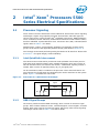
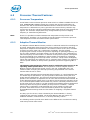
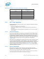
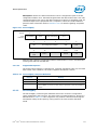
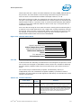
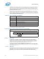
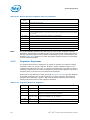
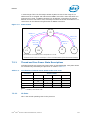
2.1.1 Intel QuickPath Interconnect
Intel Xeon Processor 5500 Series provide two Intel QuickPath Interconnect ports for
high speed serial transfer between other enabled components. Each port consists of
two uni-directional links (for transmit and receive). A differential signaling scheme is
utilized, which consists of opposite-polarity (D_P, D_N) signal pairs.
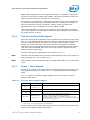
On-die termination (ODT) is included on the processor silicon and terminated to V
SS
.
Intel chipsets also provide ODT, thus eliminating the need to terminate on the system
board. Figure 2-1 illustrates the active ODT.
2.1.2 DDR3 Signal Groups
The memory interface utilizes DDR3 technology, which consists of numerous signal
groups. These include: Reference Clocks, Command Signals, Control Signals, and Data
Signals. Each group consists of numerous signals, which may utilize various signaling
technologies. Please refer to Table 2-5 for further details.
Figure 2-1. Active ODT for a Differential Link Example
T
X
R
X
R
TT
R
TT
R
TT
R
TT
Signal
Signal

Intel® Xeon® Processors 5500 Series Electrical Specifications
14 Intel
®
Xeon
®
Processor 5500 Series Datasheet, Volume 1
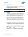
2.1.3 Platform Environmental Control Interface (PECI)
PECI is an Intel proprietary interface that provides a communication channel between
Intel processors and chipset components to external thermal monitoring devices. The
Intel Xeon Processor 5500 Series contains a Digital Thermal Sensor (DTS) that reports
a relative die temperature as an offset from Thermal Control Circuit (TCC) activation
temperature. Temperature sensors located throughout the die are implemented as
analog-to-digital converters calibrated at the factory. PECI provides an interface for
external devices to read processor temperature, perform processor manageability
functions, and manage processor interface tuning and diagnostics. Please refer to
Section 6 for processor specific implementation details for PECI.
The PECI interface operates at a nominal voltage set by V
TTD
. The set of DC electrical
specifications shown in Table 2-13 is used with devices normally operating from a V
TTD
interface supply.
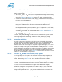
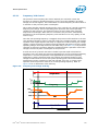
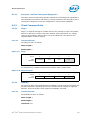
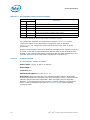
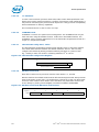
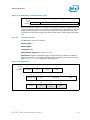
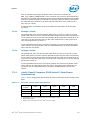
2.1.3.1 Input Device Hysteresis
The PECI client and host input buffers must use a Schmitt-triggered input design for
improved noise immunity. Please refer to Figure 2-2 and Table 2-13.
2.1.4 Processor Sideband Signals
Intel Xeon Processor 5500 Series include sideband signals that provide a variety of
functions. Details can be found in Table 2-5 and the applicable platform design guide.
All Asynchronous Processor Sideband signals are required to be asserted/deasserted
for at least eight BCLKs in order for the processor to recognize the proper signal state.
See Table 2-17 for DC specifications.
2.1.5 System Reference Clock
The processor core, processor uncore, Intel QuickPath Interconnect link, and DDR3
memory interface frequencies are generated from BCLK_DP and BCLK_DN signals.
There is no direct link between core frequency and Intel QuickPath Interconnect link
frequency (e.g., no core frequency to Intel QuickPath Interconnect multiplier). The
processor maximum core frequency, Intel QuickPath Interconnect link frequency and
Figure 2-2. Input Device Hysteresis
Minimum V
P
Maximum V
P
Minimum V
N
Maximum V
N
PECI High Range
PECI Low Range
Valid Input
Signal Range
Minimum
Hysteresis
V
TTD
PECI Ground

Intel
®
Xeon
®
Processor 5500 Series Datasheet, Volume 1 15
Intel® Xeon® Processors 5500 Series Electrical Specifications
DDR3 memory frequency are set during manufacturing. It is possible to override the
processor core frequency setting using software. This permits operation at lower core
frequencies than the factory set maximum core frequency.
The processor core frequency is configured during reset by using values stored within
the device during manufacturing. The stored value sets the lowest core multiplier at
which the particular processor can operate. If higher speeds are desired, the
appropriate ratio can be configured via the IA32_PERF_CTL MSR.
Clock multiplying within the processor is provided by the internal phase locked loop
(PLL), which requires a constant frequency BCLK_DP, BCLK_DN input, with exceptions
for spread spectrum clocking.
2.1.6 Test Access Port (TAP) Signals
Due to the voltage levels supported by other components in the Test Access Port (TAP)
logic, it is recommended that the processor(s) be first in the TAP chain and followed by
any other components within the system. A translation buffer should be used to
connect to the rest of the chain unless one of the other components is capable of
accepting an input of the appropriate voltage. Similar considerations must be made for
TCK, TDO, TMS, and TRST#. Two copies of each signal may be required with each
driving a different voltage level.
Processor TAP signal DC specifications can be found in Table 2-17.
Note: While TDI, TMS and TRST# do not include On-Die Termination (ODT), these signals are
weakly pulled-up via a 1-5 kΩ resistor to V
TT
.
Note: While TCK does not include ODT, this signal is weakly pulled-down via a 1-5 kΩ resistor
to V
SS
.
2.1.7 Power / Other Signals
Processors also include various other signals including power/ground, sense points, and
analog inputs. Details can be found in Table 2-5 and the applicable platform design
guide.
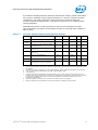
Table 2-1 outlines the required voltage supplies necessary to support Intel Xeon
Processor 5500 Series.
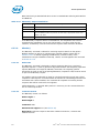
Note:
1. Refer to Table 2-8 for voltage and current specifications.
Further platform and processor power delivery details can be found in the Intel
®
Xeon
®
Processor 5500 Platform Design Guide (PDG).
Table 2-1. Processor Power Supply Voltages
1
Power Rail Nominal Voltage Notes
V
CC
See Table 2-9;
Figure 2-3
Each processor includes a dedicated VR11.1 regulator.
V
CCPLL
1.80 V
Each processor includes dedicated V
CCPLL
and PLL circuits.
V
DDQ
1.50 V
Each processor and DDR3 stack shares a dedicated voltage regulator.
V
TTA
, V
TTD
See Table 2-11;
Figure 2-10
Each processor includes a dedicated VR11.0 regulator.
V
TT
= V
TTA
+ V
TTD
; P1V1_Vtt is VID[4:2] controlled,
VID range is 1.0255-1.2000V; 20 mV offset (see Table 2-4); V
TT
represents a typical voltage. V
TT_MIN
and V
TT_MAX
loadlines represent a
31.5 mV offset from V
TT
(typ).

Intel® Xeon® Processors 5500 Series Electrical Specifications
16 Intel
®
Xeon
®
Processor 5500 Series Datasheet, Volume 1
2.1.7.1 Power and Ground Lands
For clean on-chip power distribution, processors include lands for all required voltage
supplies. These include:
•210 each V
CC
(271 ea. V
SS
) lands must be supplied with the voltage determined by
the VID[7:0] signals. Table 2-2 defines the voltage level associated with each core
VID pattern. Table 2-9 and Figure 2-3 represent V
CC
static and transient limits.
•3 each V
CCPLL
lands, connected to a 1.8 V supply, power the Phase Lock Loop (PLL)
clock generation circuitry. An on-die PLL filter solution is implemented within the
Intel Xeon Processor 5500 Series.
• 45 each V
DDQ
(17 ea. V
SS
) lands, connected to a 1.50 V supply, provide power to
the processor DDR3 interface. This supply also powers the DDR3 memory
subsystem.
•7 each V
TTA
(5 ea. V
SS
) and 26 ea. V
TTD
(17 ea. V
SS
) lands must be supplied with
the voltage determined by the VTT_VID[4:2] signals. Coupled with a 20 mV offset,
this corresponds to a VTT_VID pattern of ‘010xxx10’. Table 2-4 specifies the
voltage levels associated with each VTT
_
VID pattern. Table 2-11 and Figure 2-10
represent V
TT
static and transient limits.
All V
CC
, V
CCPLL,
V
DDQ,
V
TTA
, and V
TTD
lands must be connected to their respective
processor power planes, while all V
SS
lands must be connected to the system ground
plane. Refer to the Intel
®
Xeon
®
Processor 5500 Platform Design Guide (PDG) for
decoupling, voltage plane and routing guidelines for each power supply voltage.
2.1.7.2 Decoupling Guidelines
Due to its large number of transistors and high internal clock speeds, the Intel Xeon
Processor 5500 Series is capable of generating large current swings between low and
full power states. This may cause voltages on power planes to sag below their
minimum values if bulk decoupling is not adequate. Larger bulk storage (C
BULK
), such
as electrolytic capacitors, supply current during longer lasting changes in current
demand, for example coming out of an idle condition. Similarly, they act as a storage
well for current when entering an idle condition from a running condition. Care must be
taken in the baseboard design to ensure that the voltages provided to the processor
remains within the specifications listed in Table 2-8. Failure to do so can result in timing
violations or reduced lifetime of the processor.
2.1.7.3 Processor V
CC
Voltage Identification (VID) Signals
The voltage set by the VID signals is the maximum reference voltage regulator (VR)
output to be delivered to the processor V
CC
lands. VID signals are CMOS push/pull
outputs. Please refer to Table 2-17 for the DC specifications for these and other
processor sideband signals.
Individual processor VID values may be calibrated during manufacturing such that two
processor units with the same core frequency may have different default VID settings.
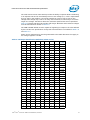
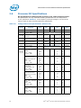
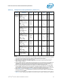
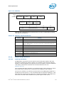
The Intel Xeon Processor 5500 Series
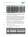
uses eight voltage identification signals,
VID[7:0], to support automatic selection of core power supply voltages. Table 2-2
specifies the voltage level corresponding to the state of VID[7:0]. A ‘1’ in this table
refers to a high voltage level and a ‘0’ refers to a low voltage level. If the processor
socket is empty (SKTOCC# high), or the voltage regulation circuit cannot supply the
voltage that is requested, the voltage regulator must disable itself.

Intel
®
Xeon
®
Processor 5500 Series Datasheet, Volume 1 17
Intel® Xeon® Processors 5500 Series Electrical Specifications
The Intel Xeon Processor 5500 Series provides the ability to operate while transitioning
to an adjacent VID and its associated processor core voltage (V
CC
). This is represented
by a DC shift in the loadline. It should be noted that a low-to-high or high-to-low
voltage state change may result in as many VID transitions as necessary to reach the
target core voltage. Transitions above the maximum specified VID are not permitted.
Table 2-8 includes VID step sizes and DC shift ranges. Minimum and maximum voltages
must be maintained as shown in Table 2-9.
The VRM or EVRD utilized must be capable of regulating its output to the value defined
by the new VID. DC specifications for dynamic VID transitions are included in Table 2-8
and Table 2-9.
Power source characteristics must be guaranteed to be stable whenever the supply to
the voltage regulator is stable.
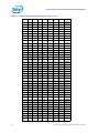
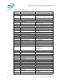
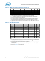
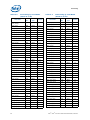
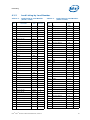
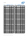
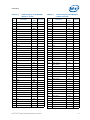
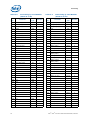
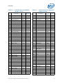
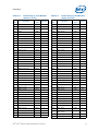
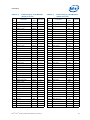
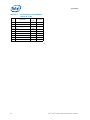
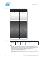
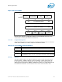
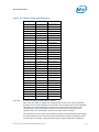
Table 2-2.Voltage Identification Definition (Sheet 1 of 5)
VID7 VID6 VID5 VID4 VID3 VID2 VID1 VID0 V
CC_MAX
000000 0 0 OFF
000000 0 1 OFF
000000 1 01.60000
000000 1 11.59375
000001 0 01.58750
000001 0 11.58125
000001 1 01.57500
000001 1 11.56875
000010 0 01.56250
000010 0 11.55625
000010 1 01.55000
000010 1 11.54375
000011 0 01.53750
000011 0 11.53125
000011 1 01.52500
000011 1 11.51875
000100 0 01.51250
000100 0 11.50625
000100 1 01.50000
000100 1 11.49375
000101 0 01.48750
000101 0 11.48125
000101 1 01.47500
000101 1 11.46875
000110 0 01.46250
000110 0 11.45625
000110 1 01.45000
000110 1 11.44375
000111 0 01.43750
000111 0 11.43125

Intel® Xeon® Processors 5500 Series Electrical Specifications
18 Intel
®
Xeon
®
Processor 5500 Series Datasheet, Volume 1
000111 1 01.42500
000111 1 11.41875
001000 0 01.41250
001000 0 11.40625
001000 1 01.40000
001000 1 11.39375
001001 0 01.38750
001001 0 11.38125
001001 1 01.37500
001001 1 11.36875
001010 0 01.36250
001010 0 11.35625
0 0 1 0 1 0 1 0 1.35000
0 0 1 0 1 0 1 1 1.34375
0 0 1 0 1 1 0 0 1.33750
0 0 1 0 1 1 0 1 1.33125
0 0 1 0 1 1 1 0 1.32500
0 0 1 0 1 1 1 1 1.31875
0 0 1 1 0 0 0 0 1.31250
0 0 1 1 0 0 0 1 1.30625
0 0 1 1 0 0 1 0 1.30000
0 0 1 1 0 0 1 1 1.29375
0 0 1 1 0 1 0 0 1.28750
0 0 1 1 0 1 0 1 1.28125
0 0 1 1 0 1 1 0 1.27500
0 0 1 1 0 1 1 1 1.26875
0 0 1 1 1 0 0 0 1.26250
0 0 1 1 1 0 0 1 1.25625
0 0 1 1 1 0 1 0 1.25000
0 0 1 1 1 0 1 1 1.24375
0 0 1 1 1 1 0 0 1.23750
0 0 1 1 1 1 0 1 1.23125
0 0 1 1 1 1 1 0 1.22500
0 0 1 1 1 1 1 1 1.21875
0 1 0 0 0 0 0 0 1.21250
0 1 0 0 0 0 0 1 1.20625
0 1 0 0 0 0 1 0 1.20000
0 1 0 0 0 0 1 1 1.19375
0 1 0 0 0 1 0 0 1.18750
0 1 0 0 0 1 0 1 1.18125
0 1 0 0 0 1 1 0 1.17500
0 1 0 0 0 1 1 1 1.16875
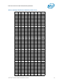
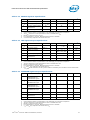
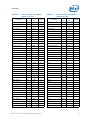
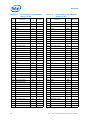
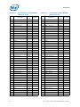
Table 2-2.Voltage Identification Definition (Sheet 2 of 5)
VID7 VID6 VID5 VID4 VID3 VID2 VID1 VID0 V
CC_MAX

Intel
®
Xeon
®
Processor 5500 Series Datasheet, Volume 1 19
Intel® Xeon® Processors 5500 Series Electrical Specifications
0 1 0 0 1 0 0 0 1.16250
0 1 0 0 1 0 0 1 1.15625
0 1 0 0 1 0 1 0 1.15000
0 1 0 0 1 0 1 1 1.14375
0 1 0 0 1 1 0 0 1.13750
0 1 0 0 1 1 0 1 1.13125
0 1 0 0 1 1 1 0 1.12500
0 1 0 0 1 1 1 1 1.11875
0 1 0 1 0 0 0 0 1.11250
0 1 0 1 0 0 0 1 1.10625
0 1 0 1 0 0 1 0 1.10000
0 1 0 1 0 0 1 1 1.09375
0 1 0 1 0 1 0 0 1.08750
0 1 0 1 0 1 0 1 1.08125
0 1 0 1 0 1 1 0 1.07500
0 1 0 1 0 1 1 1 1.06875
0 1 0 1 1 0 0 0 1.06250
0 1 0 1 1 0 0 1 1.05625
0 1 0 1 1 0 1 0 1.05000
0 1 0 1 1 0 1 1 1.04375
0 1 0 1 1 1 0 0 1.03750
0 1 0 1 1 1 0 1 1.03125
0 1 0 1 1 1 1 0 1.02500
0 1 0 1 1 1 1 1 1.01875
0 1 1 0 0 0 0 0 1.01250
0 1 1 0 0 0 0 1 1.00625
0 1 1 0 0 0 1 0 1.00000
0 1 1 0 0 0 1 1 0.99375
0 1 1 0 0 1 0 0 0.98750
0 1 1 0 0 1 0 1 0.98125
0 1 1 0 0 1 1 0 0.97500
0 1 1 0 0 1 1 1 0.96875
0 1 1 0 1 0 0 0 0.96250
0 1 1 0 1 0 0 1 0.95625
0 1 1 0 1 0 1 0 0.95000
0 1 1 0 1 0 1 1 0.94375
0 1 1 0 1 1 0 0 0.93750
0 1 1 0 1 1 0 1 0.93125
0 1 1 0 1 1 1 0 0.92500
0 1 1 0 1 1 1 1 0.91875
0 1 1 1 0 0 0 0 0.91250
0 1 1 1 0 0 0 1 0.90625
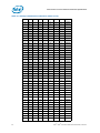
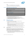
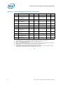
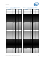
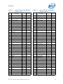
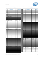
Table 2-2.Voltage Identification Definition (Sheet 3 of 5)
VID7 VID6 VID5 VID4 VID3 VID2 VID1 VID0 V
CC_MAX

Intel® Xeon® Processors 5500 Series Electrical Specifications
20 Intel
®
Xeon
®
Processor 5500 Series Datasheet, Volume 1
0 1 1 1 0 0 1 0 0.90000
0 1 1 1 0 0 1 1 0.89375
0 1 1 1 0 1 0 0 0.88750
0 1 1 1 0 1 0 1 0.88125
0 1 1 1 0 1 1 0 0.87500
0 1 1 1 0 1 1 1 0.86875
0 1 1 1 1 0 0 0 0.86250
0 1 1 1 1 0 0 1 0.85625
0 1 1 1 1 0 1 0 0.85000
0 1 1 1 1 0 1 1 0.84375
0 1 1 1 1 1 0 0 0.83750
0 1 1 1 1 1 0 1 0.83125
0 1 1 1 1 1 1 0 0.82500
0 1 1 1 1 1 1 1 0.81875
1 0 0 0 0 0 0 0 0.81250
1 0 0 0 0 0 0 1 0.80625
1 0 0 0 0 0 1 0 0.80000
1 0 0 0 0 0 1 1 0.79375
1 0 0 0 0 1 0 0 0.78750
1 0 0 0 0 1 0 1 0.78125
1 0 0 0 0 1 1 0 0.77500
1 0 0 0 0 1 1 1 0.76875
1 0 0 0 1 0 0 0 0.76250
1 0 0 0 1 0 0 1 0.75625
1 0 0 0 1 0 1 0 0.75000
100010 1 10.74375
100011 0 00.73750
100011 0 10.73125
100011 1 00.72500
100011 1 10.71875
100100 0 00.71250
100100 0 10.70625
100100 1 00.70000
100100 1 10.69375
100101 0 00.68750
100101 0 10.68125
100101 1 00.67500
100101 1 10.66875
100110 0 00.66250
100110 0 10.65625
100110 1 00.65000
100110 1 10.64375
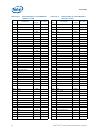
Table 2-2.Voltage Identification Definition (Sheet 4 of 5)
VID7 VID6 VID5 VID4 VID3 VID2 VID1 VID0 V
CC_MAX
Page is loading ...
Page is loading ...
Page is loading ...
Page is loading ...
Page is loading ...
Page is loading ...
Page is loading ...
Page is loading ...
Page is loading ...
Page is loading ...
Page is loading ...
Page is loading ...
Page is loading ...
Page is loading ...
Page is loading ...
Page is loading ...
Page is loading ...
Page is loading ...
Page is loading ...
Page is loading ...
Page is loading ...
Page is loading ...
Page is loading ...
Page is loading ...
Page is loading ...
Page is loading ...
Page is loading ...
Page is loading ...
Page is loading ...
Page is loading ...
Page is loading ...
Page is loading ...
Page is loading ...
Page is loading ...
Page is loading ...
Page is loading ...
Page is loading ...
Page is loading ...
Page is loading ...
Page is loading ...
Page is loading ...
Page is loading ...
Page is loading ...
Page is loading ...
Page is loading ...
Page is loading ...
Page is loading ...
Page is loading ...
Page is loading ...
Page is loading ...
Page is loading ...
Page is loading ...
Page is loading ...
Page is loading ...
Page is loading ...
Page is loading ...
Page is loading ...
Page is loading ...
Page is loading ...
Page is loading ...
Page is loading ...
Page is loading ...
Page is loading ...
Page is loading ...
Page is loading ...
Page is loading ...
Page is loading ...
Page is loading ...
Page is loading ...
Page is loading ...
Page is loading ...
Page is loading ...
Page is loading ...
Page is loading ...
Page is loading ...
Page is loading ...
Page is loading ...
Page is loading ...
Page is loading ...
Page is loading ...
Page is loading ...
Page is loading ...
Page is loading ...
Page is loading ...
Page is loading ...
Page is loading ...
Page is loading ...
Page is loading ...
Page is loading ...
Page is loading ...
Page is loading ...
Page is loading ...
Page is loading ...
Page is loading ...
Page is loading ...
Page is loading ...
Page is loading ...
Page is loading ...
Page is loading ...
Page is loading ...
Page is loading ...
Page is loading ...
Page is loading ...
Page is loading ...
Page is loading ...
Page is loading ...
Page is loading ...
Page is loading ...
Page is loading ...
Page is loading ...
Page is loading ...
Page is loading ...
Page is loading ...
Page is loading ...
Page is loading ...
Page is loading ...
Page is loading ...
Page is loading ...
Page is loading ...
Page is loading ...
Page is loading ...
Page is loading ...
Page is loading ...
Page is loading ...
Page is loading ...
Page is loading ...
Page is loading ...
Page is loading ...
Page is loading ...
Page is loading ...
Page is loading ...
Page is loading ...
Page is loading ...
Page is loading ...
-
 1
1
-
 2
2
-
 3
3
-
 4
4
-
 5
5
-
 6
6
-
 7
7
-
 8
8
-
 9
9
-
 10
10
-
 11
11
-
 12
12
-
 13
13
-
 14
14
-
 15
15
-
 16
16
-
 17
17
-
 18
18
-
 19
19
-
 20
20
-
 21
21
-
 22
22
-
 23
23
-
 24
24
-
 25
25
-
 26
26
-
 27
27
-
 28
28
-
 29
29
-
 30
30
-
 31
31
-
 32
32
-
 33
33
-
 34
34
-
 35
35
-
 36
36
-
 37
37
-
 38
38
-
 39
39
-
 40
40
-
 41
41
-
 42
42
-
 43
43
-
 44
44
-
 45
45
-
 46
46
-
 47
47
-
 48
48
-
 49
49
-
 50
50
-
 51
51
-
 52
52
-
 53
53
-
 54
54
-
 55
55
-
 56
56
-
 57
57
-
 58
58
-
 59
59
-
 60
60
-
 61
61
-
 62
62
-
 63
63
-
 64
64
-
 65
65
-
 66
66
-
 67
67
-
 68
68
-
 69
69
-
 70
70
-
 71
71
-
 72
72
-
 73
73
-
 74
74
-
 75
75
-
 76
76
-
 77
77
-
 78
78
-
 79
79
-
 80
80
-
 81
81
-
 82
82
-
 83
83
-
 84
84
-
 85
85
-
 86
86
-
 87
87
-
 88
88
-
 89
89
-
 90
90
-
 91
91
-
 92
92
-
 93
93
-
 94
94
-
 95
95
-
 96
96
-
 97
97
-
 98
98
-
 99
99
-
 100
100
-
 101
101
-
 102
102
-
 103
103
-
 104
104
-
 105
105
-
 106
106
-
 107
107
-
 108
108
-
 109
109
-
 110
110
-
 111
111
-
 112
112
-
 113
113
-
 114
114
-
 115
115
-
 116
116
-
 117
117
-
 118
118
-
 119
119
-
 120
120
-
 121
121
-
 122
122
-
 123
123
-
 124
124
-
 125
125
-
 126
126
-
 127
127
-
 128
128
-
 129
129
-
 130
130
-
 131
131
-
 132
132
-
 133
133
-
 134
134
-
 135
135
-
 136
136
-
 137
137
-
 138
138
-
 139
139
-
 140
140
-
 141
141
-
 142
142
-
 143
143
-
 144
144
-
 145
145
-
 146
146
-
 147
147
-
 148
148
-
 149
149
-
 150
150
-
 151
151
-
 152
152
-
 153
153
-
 154
154


Ask a question and I''ll find the answer in the document
Finding information in a document is now easier with AI
Related papers
Other documents
-
Intel AT80601000918AA User manual
-
-
-
-
Intel i7-2960XM Datasheet
-
Fujitsu CM8063501293407 Datasheet
-
-
Intel Xeon X3350 Datasheet
-
HP HH80562QH0678M Datasheet
-