Page is loading ...

FXVMA Installation Instructions 1
Applications
This document covers the mounting and wiring of the
FXVMA Variable Air Volume (VAV) Box Controller. For
more information about programming, configuring,
downloading, and/or commissioning the FXVMA, refer
to the FXVMA VAV Box Controller Technical Bulletin
(LIT-12011249).
The FXVMA is a VAV box controller in the Facility
Explorer line of products. The FXVMA is an integrated
assembly consisting of a high performance digital
controller, fast response actuator, and an accurate
Differential Pressure Transducer (DPT), all of which are
pre-wired together and integrated inside a single
enclosure.
The FXVMA is fully programmable using FX Builder, or
you can select and configure a pre-defined VAV box
control application using FX Builder Express.
Various software and accessories are available to
assist you during the commissioning of the FXVMA and
the VAV box. This includes FX CommPro, which has
computer-based downloading and commissioning
capabilities; and the Medium User Interface, which has
an easy-to-use hardware interface.
The FXVMA includes an embedded communication
capability that enables the FXVMA to integrate into an
N2 or BACnet® Master-Slave/Token-Passing (MS/TP)
(depending on model) network of a building automation
system.
North American Emissions Compliance
United States
Canada
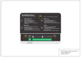
Figure 1: FXVMA VAV Box Controller
This equipment has been tested and found to
comply with the limits for a Class A digital device
pursuant to Part 15 of the FCC Rules. These limits
are designed to provide reasonable protection
against harmful interference when this equipment is
operated in a commercial environment. This
equipment generates, uses, and can radiate radio
frequency energy and, if not installed and used in
accordance with the instruction manual, may cause
harmful interference to radio communications.
Operation of this equipment in a residential area is
likely to cause harmful interference, in which case
the user will be required to correct the interference
at his/her own expense.
This Class (A) digital apparatus meets all the
requirements of the Canadian Interference-Causing
Equipment Regulations.
Cet appareil numérique de la Classe (A) respecte
toutes les exigences du Règlement sur le matériel
brouilleur du Canada.
FXVMA
Installation Instructions
LP-FXVMAxx-x
Part No. 24-10143-47, Rev. D
Issued April 16, 2009
Supersedes February 4, 2008

FXVMA Installation Instructions2
Installation
Observe these guidelines when installing the FXVMA:
• Transport the FXVMA in its original container to
minimize vibration and shock damage.
• Do not drop the FXVMA or subject it to physical
shock.
Accessories
Use Table 1 to order accessories.
Mounting
To mount the FXVMA:
1. Place the FXVMA in the proper mounting position
on the damper shaft so that the wiring connections
are easily accessible.
2. Make sure the FXVMA base is parallel to the VAV
box (perpendicular to the damper shaft). If needed,
use a spacer to offset tipping of the FXVMA caused
by the shaft bushings.
3. Secure the self-piercing No.10 screw through the
FXVMA mounting slot with a power screwdriver
and 100 mm (4 in.) extension socket; otherwise,
use a punch to mark the position of the shoulder
washer and then drill a hole into the VAV box using
a 3.5 mm (9/64 in.) drill bit.
4. Insert and tighten the mounting screw against the
washer.
5. Locate the damper position using the typical
marking on the end of the damper shaft (Figure 2).
6. Note the direction, Clockwise (CW) or
Counterclockwise (CCW), required to close the
damper.
7. Grasp the damper shaft firmly with pliers and either
manually close the damper for 90° boxes or
manually open for 45° or 60° boxes.
8. Push down and hold the Manual Override button,
and turn the FXVMA coupler until it contacts the
mechanical end-stop at either the fully closed (90°
boxes) or fully open (45° and 60° boxes) position.
Table 1: FXVMA Accessories Ordering
Information
Product
Code
Number
Description
Y64T15-0 Transformer: 120/208/240 VAC Primary
to 24 VAC Secondary, 92 VA, Foot
Mount, 30 in. Primary Leads and 30 in.
Secondary Leads, Class 2
Y65A13-0 Transformer: 120 VAC Primary to
24 VAC Secondary, 40 VA, Foot Mount,
8 in. Primary Leads and 30 in.
Secondary Leads, Class 2
Y65T42-0 Transformer: 120/208/240 VAC Primary
to 24 VAC Secondary, 40 VA, Hub
Mount, 8 in. Primary Leads and
Secondary Screw Terminals, Class 2
Y65T31-0 Transformer: 120/208/240 VAC Primary
to 24 VAC Secondary, 40 VA, Hub
Mount, 8 in. Primary Leads and
Secondary Screw Terminals, Class 2
AP-TBK1002-0 2-position screw terminal that plugs into
spade lugs
AP-TBK1003-0 3-position screw terminal that plugs into
spade lugs
IMPORTANT: When the air supply to the VAV box
is below 10°C (50°F), make sure that any
condensation on the VAV box (particularly on the
damper shaft) does not enter the electronics. Mount
the FXVMA vertically above the damper shaft to
allow any shaft condensation to fall away from the
FXVMA. Additional measures may be required in
some installations.
IMPORTANT: Do not overtighten the screws, or the
threads may strip. If you plan to mount to the VAV
box, make sure the screws do not interfere with
damper blade movement.
Figure 2: Typical Damper End Shaft Icons
FIG:d_shaft

FXVMA Installation Instructions 3
9. For 90° boxes, rotate the coupler in the direction
that the damper closes with the mechanical limit.
The open end-stop is automatically set for 90°
boxes.
You must provide hard stops for 45° and 60° boxes
at both fully closed and fully open damper
positions. By installing the FXVMA at the fully open
position, the FXVMA provides the open stop for the
box. The closed damper seal provides the fully
closed stop.
10. Tighten the square coupler bolt to 17 to 21 N·m
(150 to 185 lb·in.).
11. Loop the pneumatic tubing to include a trap for
condensation. Attach the tubing from the FXVMA to
the VAV box flow pickup. The red tubing is
connected to the inlet or high pressure side and the
clear tubing is connected to the low pressure side.
12. Push the Manual Override button, and turn the
actuator coupling manually to ensure that the
actuator can rotate from full closed to full open
positions without binding.
13. Complete the mounting by rotating the damper to
the full open position.
Wiring
To wire the FXVMA:
1. Wire the analog and binary Inputs/Outputs (I/Os) to
the FXVMA.
2. Wire the Network Room Module (NRM) to the
FXVMA.
3. Daisy-chain the N2 or BACnet MS/TP bus to the
FXVMA’s Supervisory Link.
4. Connect power wiring to the FXVMA.
The channel assignments for the inputs and outputs
vary according to the control application configuration.
Obtain the actual I/O channel assignments from
FX Builder Express or FX Builder.
The wiring connections for the inputs and outputs vary
depending on the FXVMA application.
Universal Input Wiring Details
The FXVMA features one Universal Input (UI) that you
can configure to accept either a passive sensor, an
active sensor, or a maintained dry contact switch input.
Passive Sensor Connection
The UI accepts a 0-600k ohm input signal from a
passive (resistive type) sensor. The UI has an internal
12 V, 15k ohm pullup. See Figure 3.
!
CAUTION: Risk of Property Damage.
Rotate the damper to the fully open
position before starting the air handler.
Failure to rotate the damper to the full
open position may result in damage to
the Variable Air Volume box or ductwork
when the air handler is started.
Table 2: FXVMA Universal Input Description
Terminal
Label
Function and Electrical Ratings/
Specifications
+15 V Sources 15 VDC power for active
devices
35 mA total current
IN 0-10 V Analog Input for active sensors
Internal 75k ohm pulldown
or
0-600k ohm Analog Input for passive
sensor (resistive temperature sensor)
Internal 12 V, 15k ohm pullup
or
Dry contact Binary Input
Internal 12 V, 15k ohm pullup
ICOM Signal common for IN terminal (isolated
from all other terminal commons)
Figure 3: Passive Sensor Connection
RTD TEMPERATURE
ELEMENT
+15
IN
ICOM
UNIVERSAL
FXVMA
FIG: PassiveSensor

FXVMA Installation Instructions4
Active Sensor Connection
The UI accepts a 0-10 VDC input signal from an active
sensor. The UI has an internal 75k ohm pulldown. The
active sensor can be powered externally; alternatively,
the FXVMA provides 15 VDC, 35 mA power to power
the sensor locally. See Figure 4 and Figure 5.
Dry Contact Switch Connection
The UI accepts a dry contact switch input with a 1 s
minimum pulse width (0.5 Hz at 50% duty cycle). The
UI has an internal 12 V, 15k ohm pullup.
Binary Output Wiring Details
The FXVMA features three field-connectable binary
outputs. These binary outputs are 24 VAC, 0.5 A triacs
that you can configure to control on/off devices (such
as fans, 2-position valves, and heating elements) or
incremental actuators.
Use Figure 7, Figure 8, and Figure 9 to make the
appropriate wiring connections to the Binary Outputs.
Refer to the configured FXVMA application
documentation for actual Binary Outputs used.
Figure 4: Active Sensor Connection
(Powered Externally)
mA
V
~
-
~
+
O
H
N
+15
IN
ICOM
UNIVERSAL
FXVMA
DEDICATED
24V SUPPLY
ACTIVE
SENSOR
Figure 5: Active Sensor Connection (Powered
by the FXVMA)
Ground
(Common)
Power
Output
ACTIVE
SENSOR
+15
IN
ICOM
UNIVERSAL
FXVMA
FIG: ActiveSensorVMA
Figure 6: Dry Contact Maintained Switch
Connection
MAINTAINED SWITCH
DRY CONTACT
(N.O. or N.C. as required)
+15
IN
ICOM
UNIVERSAL
FXVMA
FIG: dry contact
Table 3: FXVMA Binary Output Description
Terminal
Label
Function and Electrical Ratings/
Specifications
OUTX Sources 24~ Power (hot)
OCOMX Binary Output (24 VAC triac)
• When the binary output is activated,
OCOMX is connected to 24~ Power
(com).
• 30 VAC maximum output voltage
• 0.5 A maximum output current
• 40 mA minimum load current
Figure 7: Binary Output Connection to a
Single On/Off Device
FIG:bin_out
OUT1
OCOM1
OUT2
OCOM2
OUT3
OCOM3
+
-
FXVMA
ON/OFF
BINARY
Figure 8: Binary Output Connection to Multiple
On/Off Devices
OUT1
OCOM1
OUT2
OCOM2
OUT3
OCOM3
BINARY
+
-
+
-
+
-
FXVMA
STAGE 1
STAGE 2
STAGE
3
ON/OFF
DEVICES
BINARY OUTX ARE 24 VAC (HOT)
OCOMX are internally switched to 24 VAC common.
Figure 9: Binary Output Connection to an
Incremental Actuator
FIG: BinaryOutputIncremental
OUTX
OCOMX
OUTX
OCOMX
BINARY
HTG-O
TERMINATIONS FOR
2 WAY / 3 WAY COIL-B
VALVE
CONFIGURATIONS
HTG-O
TERMINATIONS FOR
3WAYCOIL-A
VALVE
CONFIGURATION
COM
CCW
CW
COM
CCW
CW
FXVMA
INCREMENTAL
ACTUATOR

FXVMA Installation Instructions 5
Configurable Output Wiring Details
The FXVMA features two field-connectable outputs that
you can configure to control on/off devices (such as
fans, 2-position valves, or heating elements),
incremental actuators (such as incremental valves), or
0-10 VDC proportional actuators (such as proportional
valves).
On/Off Device Connection
The configurable outputs are connected to on/off
devices as shown in Figure 10. The FXVMA provides
24 VAC, 0.5 A triacs to operate on/off devices.
Incremental Actuator Connection
The configurable outputs are connected to incremental
outputs as shown in Figure 11. The FXVMA provides
24 VAC, 0.5 A triacs to operate incremental actuators.
Proportional Actuator Connection
The configurable outputs are connected to proportional
(0-10 VDC) outputs as shown in Figure 12. The output
load minimum resistance must be 1k ohm.
Table 4: FXVMA Configurable Output Description
Terminal
Label
Function and Electrical Ratings/
Specifications
OUTX Analog Output
• Sources 0-10 VDC
• External 1k ohm minimum load
required
• 10 mA maximum output current
or
Binary Output (24 VAC triac)
• When the binary output is activated,
OUTX is connected to OCOMX
• 30 VAC maximum output voltage
• 0.5 A maximum output current
• 40 mA minimum load current
OCOMX Analog Output common
• Provides the signal common for
Configurable Output terminals when
the CO is configured for analog
output operation.
• Isolated from all other terminal
commons.
or
Binary Output common
• Provides the signal common for
Configurable Output terminals when
the CO is configured for Binary
Output operation.
• Isolated from all other terminal
commons including CO terminal
commons.
Figure 10: Configurable Output Connection to
an On/Off Device
OUT4
OCOM4
OUT5
OCOM5
CONFIGURABLE
HOT
COM
24~
GROUND
480/277/240/
208/120/24/
24VAC
+
-
FXVMA
ON/OFF
DEVICE
FIG: Configurab;eOutputOnOff
Figure 11: Configurable Output Connection to
an Incremental Actuator
FIG: ConfigurableOutputIncremental
OUT4
OCOM4
OUT5
OCOM5
CONFIGURABLE
HOT
COM
24~
GROUND
480/277/240/
208/120/24/
24VAC
INCREMENTAL
ACTUATOR
CCW
CW
COM
FXVMA
Figure 12: Configurable Output Connection to
a Proportional Actuator
FIG: ConfigurableOutputProportional
OUT4
OCOM4
OUT5
OCOM5
CONFIGURABLE
HOT
COM
24~
GROUND
480/277/240/
208/120/24/
24VAC
PROPORTIONAL
ACTUATOR
IN
24 V
COM
FXVMA

FXVMA Installation Instructions6
Network Room Module (NRM) Wiring Details
The NRM connects to the Remote Display Bus of the
FXVMA at the 4-terminal connection marked SENSOR.
You can connect the NRM up to 30.5 m (100 ft) from
the FXVMA.
Use Figure 13 to make the wiring connections between
the FXVMA and the NRM.
Supervisory Link Wiring Details
N2 Bus Wiring Details
The N2 bus is a communications network consisting of
three wires carrying RT+, RT-, and REF signals. For
more information on the N2 bus, refer to the N2
Communication Bus Technical Bulletin (LIT-636018).
N2 devices, including the FXVMA, are networked
together in a daisy-chain configuration. For runs up to
1,520 m (5,000 ft), we recommend you use stranded
22 AWG, twisted 3-conductor wire. Avoid using solid
wire when possible, as it is prone to break when pulled.
The N2 bus may be extended to a maximum length of
4,568 m (15,000 ft) using two repeaters.
Use Figure 14 to make the N2 bus connections to the
FXVMA.
BACnet MS/TP Bus Wiring Details
The BACnet MS/TP bus is a communications network
consisting of three wires carrying RT+, RT-, and REF
signals. For more information on the rules of the MS/TP
Communications Bus, refer to the MS/TP
Communications Bus Technical Bulletin
(LIT-12011034).
Use Figure 14 to make the BACnet MS/TP bus
connections to the FXVMA.
BACnet MS/TP devices, including the FXVMA, are
networked together in a daisy-chain configuration. For
runs up to 1,220 m (4,000 ft), we recommend you use
stranded 22 AWG, twisted 3-conductor wire. Avoid
using solid wire when possible as it is prone to break
when pulled.
Power Wiring Details
The FXVMA requires 24 VAC power. Use Figure 15 to
make power wiring connections.
Setup and Adjustments
Setting the N2 Address
The N2 address switch sets a unique address for the
FXVMA on the N2 bus.
Set the N2 address using the DIP switches on the face
of the FXVMA. The address equals the sum of the
numbers set to ON. For example, if the first (1), the
third (4), and the fifth (16) DIP switches are set to ON,
the device address is 21 (1 + 4 + 16 = 21). Use
addresses 3-255. See Figure 16.
Figure 13: NRM Connection
RT+ RT- COM
PWR
LL -
LL +
SENSOR
COM
NETWORK ROOM
MODULE
PWR
FXVMA
FIG: nrmconnection
Figure 14: N2 or BACnet MS/TP Bus Wiring
SHLD
RT -
RT +
SUPERVISORY LINK
TO NEXT N2 OR
BACNET DEVICE
FROM LAST N2 OR
BACNET DEVICE
COM
FXVMA
Figure 15: Power Wiring Connections
HOT
COM
24~
GROUND
480/277/240/
208/120/24/
24VAC
WHERE 2 OR MORE DEVICES
SHARE A SINGLE
TRANSFORMER, MAINTAIN
POLARITY (COM TO COM)
BETWEEN DEVICES
FXVMA
FIG: wiringconnections
Figure 16: Setting the DIP Switches to Address 21
1
2
8
6
4
3
2
1
6
8
4
2
1
O
N
FIG:FXVMA Address

FXVMA Installation Instructions 7
Setting the BACnet MS/TP MAC Address
The BACnet MS/TP MAC address switch sets a unique
address for the FXVMA on the BACnet MS/TP bus.
Set the BACnet MS/TP MAC address using the DIP
switches on the face of the FXVMA. The address
equals the sum of the numbers set to ON. For
example, if the first (1), the third (4), and the fifth (16)
DIP switches are set to ON, the device address is 21
(1 + 4 + 16 = 21). Use addresses 1-128. See Figure 16.
Setting the End-of-Line (EOL) Switch
Move the End-of-Line (EOL) termination switch to its
On position when the FXVMA is at the end of the
daisy-chain of devices on the N2 or BACnet MS/TP
bus; otherwise, leave it at its default Off position. See
Figure 17.
Troubleshooting
Use Table 5 to troubleshoot the FXVMA.
Repair Information
If the FXVMA Variable Air Volume Box Controller fails
to operate within its specifications, refer to the FXVMA
VAV Box Controller Technical Bulletin (LIT-12011249)
for a list of repair parts available.
Figure 17: EOL Switch
1
O
N
1
O
N
ON Position
OFF Position
E
O
L
_
S
w
i
t
c
h
.
c
d
r
Table 5: FXVMA Light-Emitting Diode (LED)
Codes
LED Description
Power Green
On when powered
Off when not powered
Fault Red
On during a reset
Off when the application is loaded and
operating correctly
Flashing when application is not
operating correctly or when the
application is in test mode
R/T
(Supervisory)
Green
Flashes when FXVMA transmits data to
a supervisor.
Turns off when the FXVMA receives
data.

Published in U.S.A. www.johnsoncontrols.com
FXVMA Installation Instructions8
Johnson Controls® is a registered trademark of Johnson Controls, Inc.
All other marks herein are the marks of their respective owners. © 2009 Johnson Controls, Inc.
Building Efficiency
507 E. Michigan Street, Milwaukee, WI 53202
Technical Specifications
FXVMA
Product Code Number LP-FXVMA##-#
Supply Voltage 20-30 VAC at 50 or 60 Hz (24 VAC Nominal), Class 2
Power Consumption 10 VA typical, 14 VA maximum
Power delivered to devices connected to the binary outputs (valves, relays, and similar
devices) is not included in this rating.
Ambient Operating Conditions 0 to 50°C (32 to 122°F)
Ambient Storage Conditions -40 to 70°C (-40 to 158°F)
Terminations 6.3 mm (1/4 in.) spade lugs-except communications and 24 VAC power, which are screw
terminals
Controller Addressing 3-255 for N2
1-128 for BACnet MS/TP
Communications Bus N2. For more information, refer to the N2 Communications Bus Technical Bulletin
(LIT-636018).
BACnet MS/TP. For more information, refer to the MS/TP Communication Bus Technical
Bulletin (LIT-12011034).
Mounting Mounts to VAV box damper shaft using single set screw and to duct with single mounting
screw.
Actuator Rating 4 N·m (35 lb·in) minimum; Minimum shaft length = 44 mm (1 3/4 in.)
Dimensions Width: 182 mm (7.2 in.)
Length: 182 mm (7.2 in.)
Height: 64 mm (2.5 in.)
Center of Output Hub to Center of Anti Rotation Slot: 160 mm (6.3 in.)
Weight 0.86 kg (1.9 lb)
Compliance United States
– UL Listed, File E107041, CCN PAZX, UL 916 Energy
Management Equipment
Canada
– UL Listed, File E107041, CCN PAZX7, CAN/CSA C22.2
No. 205 Signal Equipment
– Industry Canada Compliant, ICES-003
Europe
– CE Mark, EMC Directive 89/336/EEC, in accordance
with EN 61000-6-3 (2001) Generic Emission Standard
for Residential and Light Industry and EN 61000-6-2
(2001) Generic Immunity Standard for Heavy Industrial
Environment, and the Low Voltage Directive 73/23/EEC
in accordance with EN 60730-1 (1999) Automatic
electrical controls for household and similar use.
BACnet International
– Bacnet Testing Laboratories™
(BTL) 135-2004 Listed
BACnet Application Specific Controller (Pending)
The performance specifications are nominal and conform to acceptable industry standard. For application at conditions beyond these
specifications, consult the local Johnson Controls® office. Johnson Controls, Inc. shall not be liable for damages resulting from misapplication
or misuse of its products.
/