
VMA1826/1832 VAV Controller Installation Instructions
MS-VMA1826-x, MS-VMA1832-x
Part No. 24-10143-373, Rev. J
Issued September 2018
Refer to the QuickLIT website for the most up-to-date version of this document.
Applications
The VMA18 Series programmable VAV box controllers
are intended for use as functional replacements for the
VMA1410, VMA1415, VMA1420, and the VMA1440
controllers.
VMA1826 controllers are well-suited for commercial
zoning applications and can be used for pressure
dependent VAV box applications where no differential
pressure tranduser (DPT) is required.
Note: With CCT Release 10.1 and higher, VMA18 Series
controllers can be configured as either N2 devices
or as BACnet® MS/TP devices. This ability
provides a potential cost-effective protocol
upgrade path for existing customers and should
be considered when you install the controller.
Important: When you receive a VMA18 Series
controller from the factory or upgrade the
firmware or main code, the controller
defaults to using the MS/TP
communications protocol. The Load
Summary screen of CCT 10.1 and above
shows the connection as Wired Field Bus,
indicating that the MS/TP protocol is in use.
If you have an N2 application, the Load
Summary screen indicates that you need
to switch the communications protocol to
N2.
These VMA controllers feature an integral digital pressure
sensor (VMA1832 model only), a damper actuator, and
a 32-bit microprocessor. The controller's small package
size facilitates quick field installation and efficient use of
space for field replacements, while still enabling precision
control performance.
Note: Connecting an IOM to the VMA via the SA Bus
connection is not supported.
For information about sensor compatibility and
replacement, see Sensor Replacement and Reuse
Scenarios.
North American Emissions
Compliance
United States
This equipment has been tested and found to comply
with the limits for a Class A digital device pursuant to
Part 15 of the FCC Rules. These limits are designed to
provide reasonable protection against harmful
interference when this equipment is operated in a
commercial environment. This equipment generates,
uses, and can radiate radio frequency energy and, if not
installed and used in accordance with the instruction
manual, may cause harmful interference to radio
communications. Operation of this equipment in a
residential area may cause harmful interference, in which
case the users will be required to correct the interference
at their own expense.
Canada
This Class (A) digital apparatus meets all the
requirements of the Canadian Interference-Causing
Equipment Regulations.
Cet appareil numérique de la Classe (A) respecte toutes
les exigences du Règlement sur le matériel brouilleur
du Canada.
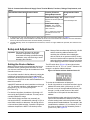
Installation
Observe these guidelines when installing a VMA18 Series
controller:
• Transport the VMA controller in the original container
to minimize vibration and shock damage to the VMA
controller.
• Do not drop the VMA controller or subject it to physical
shock.
Parts Included
• One VMA18 Series controller with removable N2/FC
bus terminal block
• One installation instructions sheet
1VMA1826/1832 VAV Controller Installation Instructions

• Two 1/4 in. x 1/4 in. (6.35 mm x 6.35 mm) brass
fittings
• One self-drilling No. 10 x 25 mm (1 in.) screw
• Two 12-in. (30.48 cm.) pieces of flexible tubing
• One controller/sensor Y cable adapter
• One 8-pin to 6-pin single-socket cable adapter
Note: Remove the cap plug from the TSTAT port of the
controller and save for future use. The cap plug
is used on existing sensor ports that are no longer
used.
Materials and Special Tools Needed
Note: You may not require all the materials listed for
your controller installation.
• Several 6 mm (1/4 in.) female spade terminals for
input and output wiring and crimping tool or spade
mounted terminal blocks
• Small straight-blade screwdriver for securing wires in
the terminal blocks
• 8 mm (5/16 in.) wrench or 10 mm (3/8 in.) 12-point
socket to tighten the square coupler bolt
• Several shims or washers to mount the VMA
• Power screwdriver, 100 mm (4 in.) extension socket,
punch, drill, and 3.5 mm (9/64 in.) drill bits to mount
the VMA
• Pliers to open and close the damper
• Required length of 3.97 mm (5/32 in.) ID pneumatic
tubing and barbed fittings
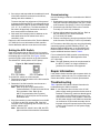
Mounting
Observe these guidelines when mounting a VMA:
Important: When the air supply to the VAV box is below
10°C (50°F), make sure that any
condensation on the VAV box, particularly
on the damper shaft, does not enter the
VMA electronics. Mount the VMA vertically
above the damper shaft to allow any shaft
condensation to fall away from the VMA.
Additional measures may be required in
some installations.
• Ensure the mounting surface can support the VMA
and any user-supplied enclosure.
• Mount the VMA on a hard, even surface whenever
possible.
• Use shims or washers to mount the VMA securely
and evenly on the mounting surface.
• Mount the VMA in an area free of corrosive vapors
that matches the ambient conditions specified in the
Technical Specifications section.
• Provide sufficient space around the VMA for cable
and wire connections and adequate ventilation
through the controller (50 mm [2 in.] minimum on the
top, bottom, sides, and front of the controllers).
• Do not mount the VMA in areas where
electromagnetic emissions from other devices or
wiring can interfere with controller communication.
• Avoid mounting the VMA on surfaces with excessive
vibration.
• Because the VMA controller is smaller than the
VMA1410, VMA1415, VMA1420, and the VMA1440
controllers, we recommend plugging the unused open
hole with the screw from the original VMA14 mounting
when using the VMA18 to replace a VMA14 Series
controller.
On panel or enclosure mount applications, observe these
additional guidelines:
• Do not install the VMA in an airtight enclosure.
• Mount the VMA so that the enclosure walls do not
obstruct cover removal or ventilation through the
controller.
• Mount the VMA so that the power transformer and
other devices do not radiate excessive heat to the
controller.
To mount the VMA18 Series controller, complete the
following steps:
1. Place the VMA18 Series controller in the proper
mounting position on the damper shaft so that the
wiring connections are easily accessible.
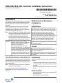
Note: The line from the captive spacer and screw
through the center of the damper shaft must
be either horizontal or vertical, and the wall
plate must be wall-mounted to comply with
requirements (Figure 1).
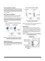
Figure 1: Possible VMA18 Series Controller
Mounting Positions
Make sure the VMA controller base is parallel to the
VAV box (perpendicular to the damper shaft). If
2VMA1826/1832 VAV Controller Installation Instructions

needed, use a spacer to offset tipping of the VMA
controller caused by the shaft bushings.
Note: Using the alignment marks to center the
captive spacer ensures sufficient VMA18
controller movement in either direction.
2. Secure the self-drilling No. 10 screw through the
shoulder washer (Figure 3) with a power screwdriver
and 100 mm (4 in.) extension socket. Otherwise, use
a punch to mark the position of the shoulder washer,
and then drill a hole into the VAV box using a 3.5 mm
(9/64 in.) drill bit. Insert the mounting screw and
tighten against the washer.
Note: The mounting screw for the VMA controller
does not use the same hole as the screw for
the VMA1410, VMA1415, VMA1420, and the
VMA1440 controller. We recommend
plugging the unused open hole with the screw
from the original VMA14 mounting when
using the VMA18 to replace a VMA14 Series
controller.
Important: Do not overtighten the screws, or the
threads may strip. If mounting to the
VAV box, make sure the screws do not
interfere with damper blade movement.
3. Locate the damper position using the typical marking
on the end of the damper shaft (Figure 2).
Figure 2: Typical Damper End Shaft Icons
4. Note the direction, clockwise (CW) or
counterclockwise (CCW), required to close the
damper. Grasp the damper shaft firmly with pliers,
and either manually close the damper (for 90° boxes)
or manually open the damper (for 45° or 60° boxes).
5. Push down and hold the Manual Override button
(Figure 3) and turn the VMA controller coupler until
it contacts the mechanical end-stop at either the fully
closed (90° boxes) or fully open (45° and 60° boxes)
position.
6. If the damper for a 90° box closes CCW, rotate the
coupler to the CCW mechanical limit. If the damper
for a 90° box closes CW, rotate the coupler to the
CW mechanical limit. The open end-stop is
automatically set for 90° boxes.
For 45° and 60° boxes, hard stops must be provided
at both fully closed and fully open damper positions.
By installing the VMA controller at the fully open
position, the VMA controller provides the open stop
for 45° and 60° boxes. The closed damper seal
provides the fully closed stop.
7. Tighten the square coupler bolt to the shaft using an
8 mm (5/16 in.) wrench or 10 mm (3/8 in.) 12-point
socket. Tighten to 10.5 to 11.5 N·m (95 to 105 lb·in).
8. Loop the pneumatic tubing to include a trap for
condensation. If needed, use the included brass
fittings and attach the included pieces of tubing to
the tubing of the VMA controller. Attach the tubing
from the VMA controller to the dual port fitting on the
VMA controller and the other ends of the tubing to
the pressure transducer in the VAV box application
(Figure 3). The VMA1826 does not come with the
tubing pieces.
Note: The VMA uses a digital non-flow pressure
sensor with bidirectional flow operation, which
allows the high- and low-pressure DP tube
connections to be made to either barbed
fitting on the VMA controller. You do not need
to make a specific high- or low-side
connection when you attach the tubing to the
barbed fittings on the VMA.
9. Push the manual release button, and turn the
actuator coupling manually to ensure that the
actuator can rotate from full-closed to full-open
positions without binding.
10. Complete the mounting by rotating the damper to
the full-open position.
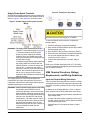
Risk of Property Damage. Rotate the damper to the
full-open position before starting the air handler. Failure
to rotate the damper to the full-open position may result
in damage to the VAV box or ductwork when the air
handler is started.
Mise En Garde: Risque de dégâts matériels: Faire
pivoter le registre pour le placer en position d'ouverture
complète avant de démarrer l'unité de traitement d'air.
Le non-respect de cette directive risque d'endommager
le caisson de l'unité à volume d'air variable (VAV) ou le
réseau de conduites au démarrage de l'unité de
traitement d'air.
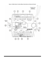
3VMA1826/1832 VAV Controller Installation Instructions

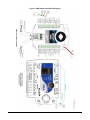
Figure 3: VMA18 Series Controller Wiring Terminations and Physical Features
4VMA1826/1832 VAV Controller Installation Instructions

Table 1: VMA18 Series Controller Feature Callout Numbers and Descriptions
Physical Features: Description and ReferencesCallout
24 VAC, Class 2 Supply Power Spade Terminals (see Supply Power Spade Terminals)
1
Device Address DIP Switch Block (see Setting the Device Address)
2
Binary Outputs, 24 VAC Triacs (see Table 4)
3
Configurable Outputs: Voltage Analog Output (0–10 VDC) and Binary Output (24 VAC Triac) (see
Table 4)
4
Dual Port Fitting (see Figure 3)
Not included in the VMA1826 model.
5
Manual Override Switch (see Mounting)
6
Controller Coupler (see Mounting)
7
Coupler Bolt (see Mounting)
8
Universal Input: Voltage Analog Input (0–10 VDC)
Resistive Analog Inputs (0–600k ohm) (see Table 4):
0–2k Potentiometer
RTD: 1k Nickel, 1k Platinum, or A99B SI
NTC: 10K Type L (10K JCI Type II is equivalent to Type L) or 2.252K Type II
Dry Contact Binary Input
9
N2/FC Bus Pluggable Screw Terminal Block (see N2/FC Bus Terminal Block)
10
EOL (End-of-Line) Switch (see Setting the EOL Switch)
11
SA Bus Spade Terminals (see SA Bus Spade Lugs)
12
TSTAT Modular Port: RJ-45 8-Pin Modular Jack (see Modular Port)
13
Captive Spacer and Screw (see Figure 3)
14
LED Status Indicators (see Table 8)
15
Wiring
Risk of Electric Shock. Disconnect the power supply
before making electrical connections to avoid electric
shock.
Mise En Garde: Risque de décharge électrique:
Débrancher l'alimentation avant de réaliser tout
raccordement électrique afin d'éviter tout risque de
décharge électrique.
Important: Do not connect supply power to the
controller before finishing wiring and
checking all wiring connections. Short
circuits or improperly connected wires can
result in damage to the controller and void
any warranty.
Important: Do not exceed the controller electrical
ratings. Exceeding controller electrical
ratings can result in permanent damage to
the controller and void any warranty.
Important: Use copper conductors only. Make all wiring
in accordance with local, national, and
regional regulations.
Important: Electrostatic discharge can damage
controller components. Use proper
electrostatic discharge precautions during
installation, setup, and servicing to avoid
damaging the controller.
For detailed information on configuring and wiring an N2
Bus, refer to the N2 Communications Bus Technical
Bulletin (LIT-636018).
VMA Terminals and Bus Ports
See Figure 3 for input and output terminal and bus port
locations on the VMA18 Series controllers. Observe the
following guidelines when wiring a VMA18 controller.
5VMA1826/1832 VAV Controller Installation Instructions

Input and Output Terminals
The input spade terminals are located on the bottom of
the VMA near the N2/FC Bus terminal block. The output
spade terminals are located on the top of the controller
near the power supply spade terminals. See Table 4 for
more information.
N2/FC Bus Terminal Block
The N2/FC Bus terminal block is a blue, removable,
4-terminal plug that fits into a board-mounted jack.
Wire the removable N2/FC Bus terminal block plugs on
the VMA and other field controllers in a daisy-chain
configuration using 3-wire twisted, shielded cable as
shown in Figure 4. See Table 5 and Table 6 for more
information.
Figure 4: N2/FC Bus Terminal Block Wiring
Note: The Shield terminal (SHLD) on the N2/FC Bus
terminal block is isolated and can be used to
connect the cable shields on the bus (Figure 4).
SA Bus Spade Lugs
Wire the SA Bus spade lugs on the VMA and other SA
Bus devices in a daisy-chain configuration using 4-wire
twisted, shielded cable as shown in Figure 5. See Table
6 for more information.
Figure 5: SA Bus Spade Lug Wiring
Note: Connecting an IOM to the VMA by using the SA
Bus connection is not supported.
Modular Port
The modular (TSTAT) port on the face of the VMA
(Figure 3) is an RJ-45, 8-position modular jack used to
connect your new or existing sensor to the VMA using
one of the two included adapters. Refer to the Sensor
Replacement section in the N2 VMA Application Note
(LIT-12011829).
Figure 6: Pin Number Assignments for the Modular
Port on VMA18 Controllers
6VMA1826/1832 VAV Controller Installation Instructions

Supply Power Spade Terminals
Wire the 24 VAC supply power wires from the transformer
to the HOT and COM terminals on the spade terminal as
shown in Figure 7. See Table 6 for more information.
Figure 7: 24 VAC Supply Power Spade Terminal
Wiring
Important: The supply power terminal block on the
VMA18 is a two-position spade lug (Figure
7). Exercise caution while rewiring the
power plug when replacing an existing
controller. Stray wire strands may make
contact and cause a short circuit across the
24 VAC power supply.
To maintain proper phasing when replacing
the existing VMA14xx controller with the
VMA18 controller, connect the power wire
from 24 VAC: 1 terminal on the existing
controller to the HOT power terminal on the
VMA18. Also connect the power wire from
the 24 VAC: 2 terminal on the existing
controller to the COM power terminal on the
VMA18 controller.
The supply power wire colors may be different on
transformers from other manufacturers. Refer to the
transformer manufacturer’s instructions and the project
installation drawings for wiring details.
Important: Connect 24 VAC supply power to the VMA
and all other network devices so that
transformer phasing is uniform across the
network devices. Powering network devices
with uniform 24 VAC supply power phasing
reduces noise, interference, and ground
loop problems. The VMA does not require
an earth ground connection. However, when
grounding the secondary of the 24 VAC
transformer is required, only one connection
to ground should be made near the
transformer.
Figure 8: Transformer Grounding
Improper wiring of this terminal may cause a short circuit
across the 24 VAC power supply on -1 models.
To wire the VMA18 Series controller, complete the
following steps:
1. Terminate wiring per engineering drawings.
2. Wire network sensors and other devices to the VMA's
Sensor/Actuator (SA) Bus.
3. Wire the N2/FC Bus in a daisy chain (see Table 6).
4. Ensure that the VMA’s device address DIP switches
are set to the appropriate device address. (See
Setting the Device Address.)
5. Connect the VMA controller to 24 VAC, Class 2
power.
Refer to the N2 VMA Application Note (LIT-12011829)
for more information about replacing an existing controller
with an VMA18 controller.
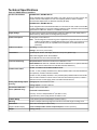
VMA Terminal Functions, Ratings,
Requirements, and Wiring Guidelines
Input and Output Wiring Guidelines
Table 4 provides information about the functions, ratings,
and requirements for the VMA input and output terminals,
and Table 5 provides guidelines for wire sizes and cable
lengths.
In addition to the wiring guidelines in Table 4, observe
these guidelines when wiring VMA inputs and outputs:
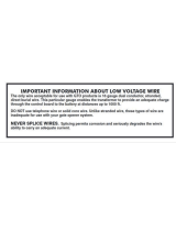
• Run all low-voltage wiring and cables separate from
high-voltage wiring.
• All input and output cables, regardless of wire size or
number of wires, should consist of twisted, insulated,
and stranded copper wires.
• Shielded cable is not required for input or output
cables.
7VMA1826/1832 VAV Controller Installation Instructions

• Shielded is recommended for input and output cables
that are exposed to high electromagnetic or radio
frequency noise.
• Cable runs of less than 30 m (100 ft) typically do not
require an offset in the input/output software setup.
Cable runs over 30 m (100 ft) may require an offset
in the input/output software setup.
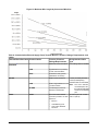
Maximum Cable Length versus Load Current
Use Figure 13 to estimate the maximum cable length
relative to the wire size and the load current (in mA) when
wiring inputs and outputs.
N2/FC and SA Bus and Supply Power Wiring
Guidelines
Table 6 provides information about terminal block
functions, ratings, and requirements.
Table 6 also provides wire size, cable type, and cable
length guidelines for wiring the VMA communication
buses and supply power.
In addition to the guidelines in Table 6, observe these
guidelines when wiring the SA and N2/FC Buses and
supply power:
• Run all low-voltage wiring and cables separate from
high-voltage wiring.
• All N2/FC and SA Bus cables, regardless of wire size,
should be twisted, insulated, stranded copper wire.
• Shielded cable is strongly recommended for all N2/FC
and SA Bus cables.
•
Refer to the N2 Communications Bus Technical
Bulletin (LIT-636018) for detailed information
regarding wire size and cable length requirements for
the N2/FC and SA buses.
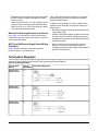
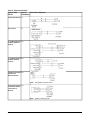
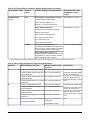
Termination Diagrams
A set of Johnson Controls® termination diagrams provides details for wiring inputs and outputs to the VMA18 Series
controllers. See the figures in this section for the applicable termination diagrams.
Table 2: Termination Details
Termination DiagramsType of
Input/Output
Type of Field
Device
UIVoltage Input -
External Source
UIVoltage Input -
Internal Source
UIVoltage Input
(Self-Powered)
8VMA1826/1832 VAV Controller Installation Instructions

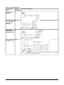
Table 2: Termination Details
Termination DiagramsType of
Input/Output
Type of Field
Device
UITemperature Sensor
UIDry Contact
CO0–10 VDC Output to
Actuator (External
Source)
CO0–10 VDC Output to
Actuator (Internal
Source)
Note: Only applies to CO4 and CO5.
CO24 VAC Triac Output
(Switch Low,
External Source)
Note: Applies to CO4 and CO5.
COIncremental Control
to Actuator (Switch
Low, External
Source)
9VMA1826/1832 VAV Controller Installation Instructions

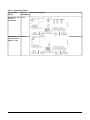
Table 2: Termination Details
Termination DiagramsType of
Input/Output
Type of Field
Device
COAnalog Output
(Voltage)
Note: Applies to BO1, BO2, and BO3.
BOIncremental Control
to Actuator (Switch
Low, Internally
Sourced)
Note: Only applies to BO1, BO2, and BO3.
BO24 VAC Binary
Output (Switch Low,
Internally Sourced)
Note: The bottom jack (J2) on the TE-700 and TE-6x00 Series Sensors are not usable
as a zone bus or an SAB connection.
SA BusTemperature Sensor
with Modular Jack
10VMA1826/1832 VAV Controller Installation Instructions

Table 2: Termination Details
Termination DiagramsType of
Input/Output
Type of Field
Device
SA BusNetwork Stat with
Terminals
Addressable
SA BusNetwork Stat with
Terminals (Fixed
Address = 199)
11VMA1826/1832 VAV Controller Installation Instructions

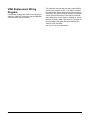
VMA Replacement Wiring
Diagram
Consider the following information when replacing a
VMA1410, VMA1415, VMA1420, and the VMA1440
controller with a VMA18 controller.
The VMA142x controller has five binary outputs (BOs)
and internally supplies 24 VAC. The VMA18 controller
has three binary outputs (BOs) and supplies 24 VAC to
these BOs. The VMA18 controller has two configurable
outputs (COs) and these two COs require an external
low voltage power source. Refer to Variable Air Volume
Modular Assembly (VMA) 1400 Series (LIT-635058) for
the Input/Output (I/O) point differences between the
VMA1410 and VMA1420.
See Figure 9 for wiring instructions.
12VMA1826/1832 VAV Controller Installation Instructions

Figure 9: VMA Replacement Wiring Diagram
13VMA1826/1832 VAV Controller Installation Instructions

Sensor Replacement and Reuse
Scenarios
This section describes sensor replacement and reuse
scenarios for replacing a VMA1410, VMA1415, VMA1420,
or the VMA controller with VMA18 controllers.
See Table 3 for a description of the most popular sensor
models used with the VMA1410, VMA1415, VMA1420,
and the VMA controllers, the sensor replacement and
reuse scenarios for that sensor model, and sensor
replacement and reuse instructions.
Important: Complete all the steps in the Mounting
section before following the instructions in
this section.
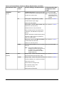
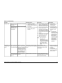
Table 3: Sensor Replacement and Reuse Scenarios
InstructionsSensor Replacement and Reuse
Scenarios
Sensor Used With VMA1410,
VMA1415, VMA1420, VMA1440
Controller
Replacing a TE-6xxx Series Sensor
Replace a sensor with an NS Series
Sensor
TE-6xxx Series (see TE-6xxx Series
Sensor Connected to VMA Controller)
Note: Replacing a TE-6xxx Series
Sensor is recommended over
reusing the sensor because it
provides a usable port at the
sensor location for
commissioning.
Reusing a TE-6xxx Series Sensor
Reuse a sensor, installing an adapter at
a VMA controller location
Replacing an AP-TMZ1600-0 Sensor
Connected to a VMA Controller
Replace a sensor with an NS Series
Sensor
AP-TMZ1600-0 (see Replacing an
AP-TMZ1600-0 Sensor Connected to a
VMA Controller)
Replacing a TE-7710-0 Series Wireless
Transmitter and TE-7720-0 Wireless
Receiver Connected to a VMA Controller
Replace with a WRZ Series Wireless
Sensor and a WRZ7860 Series
One-to-One Receiver
TE-7710-0 Series Wireless Transmitter
and TE-7720-0 Wireless Receiver (see
Replacing a TE-7710-0 Series Wireless
Transmitter and TE-7720-0 Wireless
Receiver Connected to a VMA Controller)
Replacing a TE-700 Series Sensor
Replace a sensor with a TE-730 Series
Sensor
TE-700 Series (see TE-700 Series Sensor
Connected to a VMA Controller)
Reusing a TE-700 Series Sensor
Reuse a sensor
Sensor Replacement Scenario
Descriptions
TE-6xxx Series Sensor Connected to
VMA Controller
To replace a TE-6xxx Series Sensor with a functionally
equivalent NS Series Network Sensor, follow the
instructions in the Replacing a TE-6xxx Series Sensor
section.
To reuse a TE-6xxx Series Sensor connected to a VMA
controller, follow the instructions in the Reusing a TE-6xxx
Series Sensor section.
Replacing the sensor with an NS Series Network
Sensor is preferred to reusing the TE-6xxx Series
Sensor because the NS sensor allows for easier
controller commissioning. Be sure to use an NS sensor
with similar dimensions as the existing sensor in order to
match the original sensor installation.
Note: If temporary occupancy is required for the
application on the TE-67xx and TE-68xx Series
Sensors, set the DIP switch positions on the back
of the sensor to down, up, and down. This setting
only applies to single and no setpoint controller
models (not dual setpoint controller models).
Refer to the NS Series Network Sensors Product Bulletin
(LIT-12011574) for a complete list of available NS Series
Network Sensors.
14VMA1826/1832 VAV Controller Installation Instructions

Note: In each of the following procedures that include
the use of the Commissioning Converter (BTCVT),
note the following:
The Mobile Access Portal (MAP) Gateway serves
as a replacement for the BTCVT, which is no
longer available for purchase, but continues to be
supported.
Replacing a TE-6xxx Series Sensor
To replace a TE-6xxx Series Sensor with a functionally
equivalent NS Series Network Sensor, complete the
following instructions.
Note:
• Replacing a TE-6xxx Series Sensor is recommended
over reusing the sensor.
• When replacing a TE-6xxx Series sensor with an NS
Series sensor and dissimilar paint or wall covering is
visible outside of the new sensor, consider using the
NS-WALLPLATE-0 for the new NS sensor. See Table
9 for more information.
1. Remove the TE-6xxx Series Sensor from the wall and
disconnect the 8-pin male jack from the back of the
sensor.
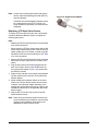
2. Plug the 8-pin male jack that was plugged into the
back of the sensor into the 8-pin female socket on
the single-socket adapter (Figure 10) provided with
the VMA18 controller.
3. Plug the 6-pin male jack on the single socket adapter
into the modular jack connection on the NS Series
Network Sensor.
4. Mount the NS Series Network Sensor in the same
location the TE-6xxx Series Sensor was previously
mounted, concealing the adapter assembly in the
existing wall opening behind the sensor. Refer to the
installation instructions for the applicable NS Series
Sensor model.
5. Plug the BTCVT into the 6-pin socket on the NS
Series Network Sensor.
Note: When using an NS Series Network Sensor with
screw terminal block terminations, see the wiring
diagram in the installation instructions for the
applicable NS Series Sensor model.
Figure 10: Single-Socket Adapter
15VMA1826/1832 VAV Controller Installation Instructions

Reusing a TE-6xxx Series Sensor
To reuse a TE-6xxx Series Sensor with the VMA
controller, complete the instructions in this section. The
Y adapter provided in the VMA18 accessory pack is
required for this procedure.
Note: The adapter must be installed at the VMA
controller location.
To install the adapter at the VMA controller location, see
Installing the Adapter at the VMA Controller Location.
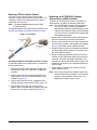
Figure 11: Y Adapter
Installing the Adapter at the VMA Controller Location
To install the adapter at the VMA location, complete the
following instructions:
1. Disconnect the 8-pin male jack that is plugged into
the VMA1410, VMA1415, VMA1420, or VMA1440
controller.
2. Plug the 8-pin male jack that was plugged into the
VMA controller into the 8-pin female socket on the
Y adapter (Figure 12).
3. Plug the 8-pin male jack on the Y adapter into the
VMA18 controller socket labeled TSTAT (Figure 12).
4. Plug the BTCVT into the 6-pin socket on the Y
adapter. When commissioning is complete, allow the
6-pin socket to remain unconnected (Figure 12).
Replacing an AP-TMZ1600-0 Sensor
Connected to a VMA Controller
To replace an AP-TMZ1600-0 sensor connected to a
VMA controller, complete the following instructions.
Note: The AP-TMZ1600-0 sensor is not supported for
use with the VMA18 controller and must be
replaced with an NS Series Network Sensor. Refer
to the NS Series Network Sensors Product Bulletin
(LIT-12011574) for a complete list of available NS
Series Network Sensors.
1. Remove the AP-TMZ1600-0 sensor and disconnect
the 8-pin male jack from the back of the sensor.
2. Plug the 8-pin male jack from the VMA controller into
the 8-pin female socket on the single-socket adapter
(Figure 10) included with the VMA18 controller.
3. Plug the 6-pin male jack on the single socket adapter
into the modular jack connection on the back of the
NS Series Network Sensor.
4. Mount the NS Series Network Sensor in the same
location the AP-TMZ1600-0 Sensor was previously
mounted, concealing the adapter assembly in the
existing wall opening behind the sensor. Refer to the
installation instructions for the applicable NS Series
Sensor model.
5. Plug the BTCVT into the 6-pin socket on the NS
Series Network Sensor.
Note: When using an NS Series Network Sensor with
screw terminal block terminations, see the wiring
diagram in the installation instructions for the
applicable NS Series Sensor model.
16VMA1826/1832 VAV Controller Installation Instructions

Replacing a TE-7710-0 Series Wireless
Transmitter and TE-7720-0 Wireless Receiver
Connected to a VMA Controller
To replace a TE-7710-0 Series Wireless Transmitter and
TE-7720-0 Wireless Receiver connected to a VMA
controller, or to convert the wired sensors used with the
VMA18 controller to wireless, complete the following
instructions .
Note: The TE-7710-0 Series Wireless Transmitter and
TE-7720-0 Wireless Receiver must both be
replaced with aWRZ Series Wireless Sensor and
a WRZ7860-0 Series One-to-One Receiver. Refer
to the WRZ Series Wireless Room Sensors
Product Bulletin (LIT-12011653) for a complete
list of available WRZ Series Wireless Room
Sensors.
1. Disconnect the 6-foot interface cable connecting the
VMA controller and the TE-7720-0 Wireless Receiver.
2. Plug one end of the 6-foot interface cable into the
VMA18 socket labeled TSTAT.
3. Plug the other end of the 6-foot interface cable into
the 8-pin female socket of the single-socket adapter.
4. Plug the male end of the single-socket adapter directly
into the BTCVT.
5. Complete commissioning of the VMA18 controller and
disconnect the BTCVT.
Note: Sensor point information such as temperature,
setpoint, and occupancy is not available during
commissioning.
6. Install the WRZ Series Wireless Sensor and a
WRZ7860-0 Series One-to-One Receiver in the same
locations as the previous sensor and receiver. Refer
to the WRZ Series Wireless Room Sensors
Installation Instructions (Part No. 24-10332-2) and
the WRZ-7860-0 Installation Instructions (Part No.
24-10563-47).
7. Plug the 6-pin male jack on the adapter into the
WRZ7860-0 receiver.
Note: When using an WRZ Series Sensor with screw
terminal block terminations, refer to the wiring
diagram in the installation instructions for the
applicable WRZ Series Sensor model.
TE-700 Series Sensor Connected to a VMA
Controller
To replace a TE-700 Series Sensor with a TE-730 Series
Sensor, follow the instructions in Replacing a TE-700
Series Sensor.
To reuse a TE-700 Series Sensor connected to a VMA
controller, follow the instructions inReusing a TE-700
Series Sensor.
Replacing a TE-700 Series Sensor
Replace a TE-700 Series Sensor with a TE-730 Series
Sensor. No cable adapters are required for this scenario.
Note: Refer to the TE-730 Series Sensor Installation
Instructions (Part No. 24-10674-0) to install the
TE-730 Series Sensor.
Reusing a TE-700 Series Sensor
See the instructions in this section to reuse a TE-700
Series Sensor when connected to a VMA18 controller.
1. Disconnect the 8-pin male jack plugged into the VMA
controller.
2. Plug the 8-pin male jack on the Y adapter (Figure 10)
provided with the VMA controller into the 8-pin female
socket labeled TSTAT on the VMA18 controller.
3. Plug the 8-pin male jack that was plugged into the
VMA controller into the 8-pin female socket of the Y
adapter.
Note: The 6-pin connection is not used for this
scenario and it should remain unconnected.
4. Refer to the TE-730 Series Sensor Installation
Instructions (Part No. 24-10674-0) to install the
TE-730 Series Sensor.
Figure 12: Y Adapter at Controller Location
17VMA1826/1832 VAV Controller Installation Instructions

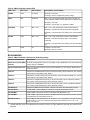
Table 4: I/O Terminal Blocks, Functions, Ratings, Requirements, and Cables
To Determine Wire Size
and Maximum Cable
Length
1
Function, Ratings, and RequirementsTerminal
Labels
Terminal Block Label
Same as (Universal) INn.
Note: Use 3-wire cable for
devices that source
power from the +15 V
terminal.
15 VDC Power Source for active (3-wire) input
devices connected to the Universal INn terminals.
Provides 35 mA total current.
+15 VUNIVERSAL
(Inputs)
See Guideline A in Table 5.
Analog Input - Voltage Mode (0–10 VDC)
10 VDC maximum input voltage
Internal 75k ohm Pulldown
INn
See Guideline A in Table 5.
Analog Input - Resistive Mode (0–600k ohm)
Internal 12 V, 15k ohm pull up
Qualified Sensors: 0–2k potentiometer,
RTD (1k Nickel [Johnson Controls® sensor],
1k Platinum, and A99B Silicon Temperature
Sensor)
Negative Temperature Coefficient (NTC) Sensor
10K Type L (10K JCI Type II is equivalent to
Type L) or 2.252K Type II
See Guideline A in Table 5.
Binary Input - Dry Contact Maintained Mode
1 second minimum pulse width
Internal 12 V, 15k ohm pull up
Same as (Universal) INn.Universal Input Common for all Universal INn
terminals
Note: All Universal ICOMn terminals are
isolated from all other commons on the
-0 models. The -1 model ICOMn
terminals are isolated from FC BUS
COM terminals only.
ICOMn
See Guideline C in Table 5.
Binary Output - 24 VAC Triac (Internal Power)
Sources internal 24 VAC power (24~ HOT)
OUTn
BINARY
(Outputs)
See Guideline C in Table 5.
Binary Output - 24 VAC Triac (Internal Power)
Connects OCOMn to 24~ COM when activated.
Internal Power Source:
30 VAC maximum voltage to load
0.5 A maximum output current
1.3 A at 25% duty cycle
40 mA minimum load current
OCOMn
18VMA1826/1832 VAV Controller Installation Instructions

Table 4: I/O Terminal Blocks, Functions, Ratings, Requirements, and Cables
To Determine Wire Size
and Maximum Cable
Length
1
Function, Ratings, and RequirementsTerminal
Labels
Terminal Block Label
See Guideline A in Table 5.
Analog Output - Voltage Mode (0–10 VDC)
10 VDC maximum output voltage
10 mA maximum output current
External 1k to 50K ohm load required
OUTn
CONFIGURABLE
(Outputs)
See Guideline C in Table 5.
Binary Output 24 VAC Triac
Connects OUT to OCOM when activated.
External Power Source:
30 VAC maximum voltage to load
0.5 A maximum output current
1.3 A at 25% duty cycle
40 mA minimum load current
Same as (Configurable) OUTn.
Analog Output Signal Common: All
Configurable Outputs defined as Analog Outputs
share a common, which is isolated from all other
commons except the Binary Input common.
OCOMn
Binary Output Signal Common: All
Configurable Outputs defined as Binary Outputs
are isolated from all other commons, including
other Configurable Output commons.
1
Table 5 defines cable length guidelines for the various wire sizes that may be used for input and output wiring.
Table 5: Cable Length Guidelines for Recommended Wire Sizes
AssumptionsMaximum Cable Length
and Type
Wire Size/Gauge and TypeGuideline
100 mV maximum voltage drop
Depending on the cable length
and the connected input or
output device, you may have to
define an offset in the setup
software for the input or output
point.
457 m (1,500 ft) twisted wire1.0 mm (18 AWG) stranded copperA
297 m (975 ft) twisted wire0.8 mm (20 AWG) stranded copper 297 m
(975 ft) twisted wire
183 m (600 ft) twisted wire0.6 mm (22 AWG) stranded copper 183 m
(600 ft) twisted wire
107 m (350 ft) twisted wire24 AWG stranded copper 107 m (350 ft)
twisted wire
100 mV maximum voltage drop
Depending on the cable length
and the connected input or
output device, you may have to
define an offset in the setup
software for the input or output
point.
229 m (750 ft) twisted wire1.0 mm (18 AWG) stranded copperB
137 m (450 ft) twisted wire0.8 mm (20 AWG) stranded copper 297 m
(975 ft) twisted wire
91 m (300 ft) twisted wire0.6 mm (22 AWG) stranded copper 183 m
(600 ft) twisted wire
61 m (200 ft) twisted wire24 AWG stranded copper 107 m (350 ft)
twisted wire
N/A
See Figure 13 to determine
cable length.
Use twisted wire cable.
See Figure 13 to select wire size/gauge.
Use stranded copper wire.
C
19VMA1826/1832 VAV Controller Installation Instructions

Figure 13: Maximum Wire Length by Current and Wire Size
Table 6: Communication Bus and Supply Power Terminal Blocks, Functions, Ratings, Requirements, and
Cables
Recommended Cable
Type
2
Function, Electrical
Ratings/Requirements
Terminal LabelsTerminal Block/Port Label
Use existing cable or 18 AWGN2/FC Bus Communications+
-
N2/FC BUS
2
Signal Reference (Common)
for bus communications
COM
Isolated terminal (optional
shield drain connection)
SHLD
0.6 mm (22 AWG) stranded,
4-wire (2 twisted-pairs),
shielded cable recommended
Note: The + and - wires are
one twisted pair, and
the COM and SA PWR
are the second twisted
pair.
SA Bus Communications+
-
SA BUS
SA Bus Signal Reference and
15 VDC Common
COM
15 VDC Supply Power for
Devices on the SA Bus
SA PWR
24 AWG 3-pair CAT 3 Cable
<30.5 m (100 ft)
RJ-45 8-Position Modular
Connector provides +15 VDC
Power for:
•
BTCVT
3
• VAV Balancing Tool
• One-to-One Wireless
Receiver
TSTATTSTAT
20VMA1826/1832 VAV Controller Installation Instructions
Page is loading ...
Page is loading ...
Page is loading ...
Page is loading ...
Page is loading ...
Page is loading ...
-
 1
1
-
 2
2
-
 3
3
-
 4
4
-
 5
5
-
 6
6
-
 7
7
-
 8
8
-
 9
9
-
 10
10
-
 11
11
-
 12
12
-
 13
13
-
 14
14
-
 15
15
-
 16
16
-
 17
17
-
 18
18
-
 19
19
-
 20
20
-
 21
21
-
 22
22
-
 23
23
-
 24
24
-
 25
25
-
 26
26


Johnson Controls VMA18 Series Installation Instructions Manual
- Type
- Installation Instructions Manual
- This manual is also suitable for
Ask a question and I''ll find the answer in the document
Finding information in a document is now easier with AI
Related papers
-
Johnson Controls Metasys FAC4911 Installation guide
-
-
-
-
-
-
-
-
Johnson Controls FAC3613 Installation guide
-
Other documents
-
 Mighty Mule RB509-500 Installation guide
-
 Mighty Mule RB509-100 Operating instructions
-
König SEC-PCM10 Datasheet
-
Ewent EW9001 Datasheet
-
Xantech TV Cables HDMIEXTEND User manual
-
PEAK OEM 32 Installation Instructions Manual
-
Carrier VAV Zone II Installation And Startup Manual
-
HP VMA-series Memory Arrays Installation guide
-
Honeywell CentraLine LYNX BACnet CLLYVB4022AS Product information
-

