Page is loading ...

1
Tower Mantel and Base
Assembly Instructions
MODEL: AT-C
NOTE: Carefully inspect each part for shipping damage before beginning assembly. Compare the carton contents
with the list above. All necessary hardware is provided to fasten the mantel parts together. When tightening
screws, do not over tighten. This may cause threads to strip. For this reason, we recommend using a manual
screwdriver rather than a power screwdriver. Do not force screws into holes.
IMPORTANT: Read instructions carefully before starting assembly and installation of mantel. This mantel is only
approved for use with HeartSense brand gas replace system. Do not use mantel with any other brand products.
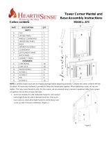
Carton contents
PART DESCRIPTION QTY
PARTS
A BASE 1
B LEFT BOTTOM BOARD 1
C RIGHT BOTTOM BOARD 1
D LEFT BOTTOM COLUMN 1
E RIGHT BOTTOM COLUMN 1
F SHELF 1
G SHELF 1
H BACK BOARD 1
I DRAWER ASSSEMBLY 1
J LEFT TOP COLUMN 1
K RIGHT TOP COLUMN 1
L LEFT TOP BOARD 1
M RIGHT TOP BOARD 1
N FRONT PANEL 1
O TOP 1
U CONNECTOR PANEL 2
HARDWARE
P CAM DOWEL 50
Q WOOD DOWEL 24
R CAM LOCK 50
S SCREW 1 4
T SCREW 2 8
V SHELF DOWEL 8
W SCREW 3 2
Figure 1

2
2
TABLE OF CONTENTS
1. Place 4 WOOD DOWELS (Q) and screw 6 CAM DOWELS (P)
into LEFT/RIGHT BOARD (B&C) as shown in Figure 2. Insert 6
CAM LOCKS (R) into the mating holes in the back of the BACK
BOARD (H) with triangle arrow pointing towards the hole in the
edge. Mate the BACK BOARD (H) with the WOOD DOWELS
(Q) and CAM DOWELS (P) in LEFT/RIGHT BOTTOM BOARD
(B&C) and twist CAM LOCKS (R) clockwise with a screwdriver to
tighten side board to back board. Then place 4 WOOD DOWELS
(Q) and screw 6 CAM DOWELS (P) into LEFT/RIGHT BOTTOM
COLUMN (D&E). Insert 6 CAM LOCKS (R) into the mating
holes in LEFT/RIGHT BOARD (B&C) with triangle arrow pointing
towards the hole in the edge. Mate the LEFT/RIGHT BOTTOM
COLUMN (D&E) with the WOOD DOWELS (Q) and CAM
DOWELS (P) in LEFT/RIGHT BOARD (B&C) and twist CAM
LOCKS (R) clockwise with a screwdriver to tighten side columns
to side board.
2. Lay BASE (A) down on a soft surface to avoid damaging the
surface and nish. Place 3 WOOD DOWELS (Q) and screw
8 CAM DOWELS (P) into the BASE (A) as shown in Figure 3.
Insert 8 CAM LOCKS (R) into the mating holes in the part already
assembled in Step 1 with triangle arrow pointing towards the
hole in the edge. Mate the pre-assembled part with the WOOD
DOWELS (Q) and CAM DOWELS (P) in the BASE (A) and twist
CAM LOCKS (R) clockwise with a screwdriver. Insert 8 SHELF
DOWELS (V) into LEFT/RIGHT BOARD (B&C) tightly. Carefully
put SHELVES (G&F) against the SHELVE DOWELS (V). Remove
handle wrapper
3. Place 3 WOOD DOWELS (Q) and screw 8 CAM DOWELS (P)
into the DRAWER ASSEMBLY (I) as shown in Figure 4. Insert 8
CAM LOCKS (R) into the mating holes in the BASE ASSEMBLY
with the triangle arrow pointing towards the hole in the edge.
Mate the BASE ASSEMBLY with WOOD DOWELS (Q) and CAM
DOWELS (P) in DRAWER ASSEMBLY (I) and twist CAM LOCKS
(R) clockwise with a screwdriver to tighten DRAWER ASSEMBLY
to BASE ASSEMBLY.
Figure 2
Figure 3

333
IMPORTANT SAFETY INFORMATION
4. Place 6 WOOD DOWELS (Q) and screw 8 CAM DOWELS
(P) into the FRONT PANEL (N) as shown in Figure 5. Insert
8 CAM LOCKS (R) into the mating holes in the LEFT/RIGHT
TOP BOARD (L&M) with the triangle arrow pointing towards
the hole in the edge. Mate the LEFT/RIGHT TOP BOARD
(L&M) with WOOD DOWELS (Q) and CAM DOWELS (P) in
FRONT PANEL (N) and twist CAM LOCKS (R) clockwise with
a screwdriver to tighten the two boards to the panel.
5. Place 2 WOOD DOWELS (Q) and screw 6 CAM DOWELS
(P) into top of the DRAWER ASSEMBLY (I) as shown in
Figure 6. Insert 6 CAM LOCKS (R) into the mating holes in
the HEARTH MANTEL ASSEMBLY nished in Step 4 with
the triangle arrow pointing towards the hole in the edge.
Mate the HEARTH MANTEL ASSEMBLY nished in Step
4 with the WOOD DOWELS (Q) and CAM DOWELS (R) in
BASE ASSEMBLY and twist CAM LOCKS (R) clockwise with
a screwdriver to tighten HEARTH MANTEL ASSEMBLY to
BASE ASSEMBLY.
6. Place 2 WOOD DOWELS (Q) and screw 6 CAM DOWELS
(P) into the TOP (O) as shown in Figure 7. Insert 6 CAM
LOCKS (R) into the mating holes in the assembled part
nished in Step 5 with triangle arrow pointing towards the
hole in the edge. Mate the BASE with WOOD DOWELS (Q)
and CAM DOWELS (P) in TOP (O) and twist CAM LOCKS
(R) clockwise with a screwdriver to tighten the TOP (O) to the
pre-assembled part in Step 5.
Figure 4
Figure 5
Figure 6
Figure 7

444
IMPORTANT SAFETY INFORMATION
GAS FIREPLACE INSTALLATION
1. Fireplace should be fully assembled. Refer to replace owner’s manual.
2. Place mantel assembly close to installation location. Refer to replace owner’s manual for installation clearances.
Provide enough room to insert replace from back of mantel.
3. Install gas line per the requirements outlined in the replace owner’s manual. Remember to leave access to the
gas shutoff valve where it is accessible to the user.
4. Check for leaks per the instructions in the replace owner’s manual.
5. Position replace inside mantel (see Figure 8). Carefully position gas lines. Important: Use caution when position
ing replace on base. Base may scratch easy. Make sure replace is in proper position within mantel opening.
6.Place the Fireplace into the Tower Mantel according to gure 6, then take out CONNECTOR PANEL (U) and
SCREW (S) (T) from the attached package; assemble the Complete Unit and High Mantel with these stuff accord
ing to Figure 9.
7. Carefully push mantel and base into position against wall.
Note: We recommend you secure the upper portion of the mantel to the wall.
8. Complete the replace assembly of log placement and front panel by following the instructions in the replace
owner’s manual.
Figure 8
Figure 9
Questions about installation, operation, or troubleshooting? Before returning to your retailer, call
customer service department toll-free at (877)886-5989.
/


