Page is loading ...

Mantel Assembly
Instructions
MODEL: AMF-CC/LM
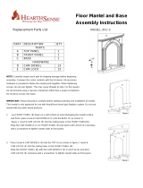
Replacement Parts List
PART DESCRIPTION QTY
PARTS
A TOP PANEL 1
B FRONT PANEL 1
C LEFT PANEL 1
D RIGHT PANEL 1
E BASE 1
HARDWARE
F CAM DOWEL 20
G CAM LOCK 20
H SCREW 4
NOTE: Carefully inspect each part for shipping damage before beginning assembly. Compare the carton contents
with the list above. All necessary hardware is provided to fasten the mantel parts together. When tightening
screws, do not over tighten. This may cause threads to strip. For this reason, we recommend using a manual
screwdriver rather than a power screwdriver. Do not force screws into holes.
1. Lay FRONT PANEL (B) down on a soft surface to avoid damaging the mantel surface
and finish. place screw 6 CAM DOWELS (F) into the FRONT PANEL (B) as shown in
figure 1. Insert 6 CAM LOCKS (G) into the mating holes in the LEFT SIDE (C) and
RIGHT SIDE (D) with the triangle arrow pointing towards the hole in the edge. Mate
the LEFT SIDE (C) and RIGHT SIDE (D) with the CAM DOWELS (F) in FRONT
PANEL (B) and twist CAM LOCKS (G) clockwise with a screwdriver to
tighten mantel sides to front panel.
Figure 1
2. Place screw 6 CAM DOWELS (F) into the BASE (E) as shown in figure 2. Insert 6
CAM LOCKS (G) into the mating holes in the LEFT SIDE (C), RIGHT SIDE (D) and
FRONT PANEL (B) with the triangle arrow pointing towards the hole in the edge.
Mate the LEFT SIDE (C), RIGHT SIDE (D) and FRONT PANEL (B) with the CAM
DOWELS (F) in and BASE (E) and twist CAM LOCKS (G) clockwise with a
screwdriver to tighten mantel sides to front panel.
Figure 2

3. Place Screw 6 CAM DOWELS (F) into the TOP (A) as shown in figure 3. Insert 6
CAM LOCKS (G) into the mating holes in the LEFT SIDE (C), RIGHT SIDE (D)
and FRONT PANEL (B) with the triangle arrow pointing towards the hole in the edge.
Mate the LEFT SIDE (C), RIGHT SIDE (D) and FRONT PANEL (B) with the CAM
DOWELS (F) in and Top (A) and twist CAM LOCKS (G) clockwise with a screwdriver
to tighten mantel sides to front panel.
Figure 3
FIREPLACE INSTALLATION
1. Fireplace should be fully assembled. Refer to fireplace owner’s manual.
2. Place mantel assembly close to installation location. Refer to fireplace owner’s
manual for installation clearances. Provide enough room to insert fireplace from back of mantel.
3. Insert fireplace into mantel. (Figure 4)
4. Turnover four metal sheets 90 degree on fireplace shell. (Figure 5) Figure 4
5. Fix fireplace to mantel with 4 Screws (H). (Figure 6)
6. Carefully push mantel and base into position against wall.
Questions about installation, operation, or troubleshooting? Before returning to
your retailer, Call customer service department toll-free at (877)886-5989.
Figure 5
Figure 6
Printed in China
/
