
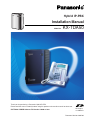
Model No.
KX-TDA50
Hybrid IP-PBX
Installation Manual
Thank you for purchasing a Panasonic Hybrid IP-PBX.
Please read this manual carefully before using this product and save this manual for future use.
KX-TDA50: PSMPR Software File Version 4.0000 or later
Document Version: 2007-04
SD Logo is
a trademark.

2 Installation Manual
System Components
Compatible Panasonic Proprietary Telephones
The Hybrid IP-PBX supports the following telephones:
• Digital proprietary telephones (e.g., KX-T7600 series)
• Analog proprietary telephones (e.g., KX-T7700 series)
• IP proprietary telephones (e.g., KX-NT136)
• Portable stations (e.g., KX-TD7690)
• DSS consoles (e.g., KX-T7640)
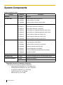
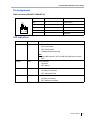
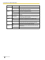
System Components Table
Category Model No. Description
Main Unit KX-TDA50 Main Unit
CO Line Cards KX-TDA5180 4-Port Analog Trunk Card (LCOT4)
KX-TDA5193 4-Port Caller ID Card (CID4)
KX-TDA5480 4-Channel VoIP Gateway Card (IP-GW4)
Extension Cards KX-TDA5170 4-Port Hybrid Extension Card (HLC4)
KX-TDA5171 4-Port Digital Extension Card (DLC4)
KX-TDA5172 8-Port Digital Extension Card (DLC8)
KX-TDA5173 4-Port Single Line Telephone Extension Card (SLC4)
KX-TDA5174 8-Port Single Line Telephone Extension Card (SLC8)
KX-TDA5175 4-Port Proprietary Extension Card (PLC4)
KX-TDA5176 8-Port Proprietary Extension Card (PLC8)
KX-TDA5470 4-Channel VoIP Extension Card (IP-EXT4)
Other Cards KX-TDA5105 Memory Expansion Card (MEC)
KX-TDA5161 4-Port Doorphone Card (DPH4)
KX-TDA5166 8-Channel Echo Canceller Card (ECHO8)
KX-TDA5168 Extension Caller ID Card (EXT-CID)
KX-TDA5191 2-Channel Message Card (MSG2)
KX-TDA5192 2-Channel Simplified Voice Message Card (SVM2)
KX-TDA5196 Remote Card (RMT)
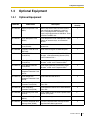
Optional SD Memory Card KX-TDA5920 SD Memory Card for Software Upgrade to Enhanced Version
Cell Station (CS) KX-T0141 2-Channel Cell Station Unit for 2.4 GHz Portable Station
Proprietary Equipment KX-A236 Additional AC Adaptor
KX-T30865 Doorphone

Installation Manual 3
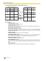
Incompatible Panasonic Proprietary Telephones
The Hybrid IP-PBX does not support the following telephones:
• KX-T30800 series proprietary telephones and DSS consoles
• KX-T61600 series proprietary telephones and DSS consoles
• KX-T123200 series proprietary telephones and DSS consoles
Notes
• For the equipment (e.g., Add-on Key Module, USB Module, Headset
*1
) that can be connected to a
particular telephone, refer to the telephone's manual.
• For other equipment that can be connected to the Hybrid IP-PBX, refer to "1.2.2 System
Connection Diagram".
List of Abbreviations
•APT → Analog proprietary telephone
•DPT → Digital proprietary telephone
• IP-PT → IP proprietary telephone
•PS → Portable station
•PT → Proprietary telephone
•SLT → Single line telephone
*1
The KX-T7090 headset can be connected to the KX-T7000, KX-T7200, KX-T7300, KX-T7400 series telephones.
Important Notice
Prior to connection of this product, please verify that the intended operating environment is supported.
Satisfactory performance cannot be guaranteed for the following:
– interoperability and compatibility with all devices and systems connected to this product
– proper operation and compatibility with services provided by telecommunications companies over
connected networks

4 Installation Manual
Important Safety Instructions
SAFETY REQUIREMENTS
When using your telephone equipment, basic safety precautions should always be followed to reduce the
risk of fire, electric shock and injury to persons, including the following:
1. Read and understand all instructions.
2. Follow all warnings and instructions marked on the product.
3. Unplug this product from the wall outlet before cleaning. Do not use liquid cleaners or aerosol cleaners.
Clean with a damp cloth.
4. Do not use this product near water, for example, near a bathtub, wash bowl, kitchen sink, or laundry
tub, in a wet basement, or near a swimming pool.
5. Do not place the product on an unstable surface, as a fall may cause serious internal damage.
6. Slots and openings in the front, back and bottom of the cabinet are provided for ventilation; to protect
it from overheating, these openings must not be blocked or covered. The openings should never be
blocked by placing the product on a bed, sofa, rug, or other similar surface while in use. The product
should never be placed near or over a radiator or other heat source. This product should not be placed
in a sealed environment unless proper ventilation is provided.
7. The product should only be connected to the type of electrical power supply specified on the product
label. If you are not sure of the type of power supply to your home, consult your dealer or local power
company.
8. For safety purposes this unit is equipped with a grounded plug. If you do not have a grounded outlet,
please have one installed. Do not bypass this safety feature by tampering with the plug.
9. Do not allow anything to rest on the power cord. Do not locate this product where the power cord may
be stepped on or tripped on.
10. To reduce the risk of fire or electric shock, do not overload wall outlets and extension cords.
11. Do not insert objects of any kind into this product through its slots and openings, as they may touch
dangerous voltage points or short out parts that could result in a risk of fire or electric shock. Never spill
liquid of any kind on or in the product.
12. To reduce the risk of electric shock, do not disassemble this product. Only qualified personnel should
service this product. Opening or removing covers may expose you to dangerous voltages or other risks.
Incorrect reassembly can cause electric shock.
13. Unplug this product from the wall outlet and have it serviced by qualified service personnel in the
following cases:
a) When the power supply cord or plug is damaged or frayed.
b) If liquid has been spilled into the product.
c) If the product has been exposed to rain or water.
d) If the product does not operate according to the operating instructions. Adjust only the controls that
are explained in the operating instructions. Improper adjustment of other controls may result in
damage and may require service by a qualified technician to restore the product to normal
operation.
e) If the product has been dropped or the cabinet has been damaged.
f) If product performance deteriorates.
14. Avoid using wired telephones during an electrical storm. There is a remote risk of electric shock from
lightning.
15. Do not use a telephone in the vicinity of a gas leak to report the leak.

Installation Manual 5
SAVE THESE INSTRUCTIONS

6 Installation Manual
Precaution
WARNING
DO NOT REMOVE
SD MEMORY CARD
WHILE POWER IS
SUPPLIED TO THE
HYBRID. IP-PBX
Doing so may cause the Hybrid IP-PBX
to fail to start when you restart the
system.

Installation Manual 7
• Keep the unit away from heating appliances and devices that generate electrical noise such as
fluorescent lamps, motors and televisions. These noise sources can interfere with the performance of
the Hybrid IP-PBX.
• This unit should be kept free of dust, moisture, high temperature (more than 40 °C [104 °F]) and
vibration, and should not be exposed to direct sunlight.
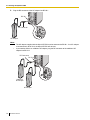
• If you are having problems making calls to outside destinations, follow this procedure to test the CO
lines:
1. Disconnect the Hybrid IP-PBX from all CO lines.
2. Connect known working SLTs to those CO lines.
3. Make a call to an external destination using those SLTs.
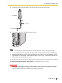
If a call cannot be carried out correctly, there may be a problem with the CO line that the SLT is
connected to. Contact your telephone company.
If all SLTs operate properly, there may be a problem with your Hybrid IP-PBX. Do not reconnect the
Hybrid IP-PBX to the CO lines until it has been serviced by an authorized Panasonic Factory Service
Center.
• Wipe the unit with a soft cloth. Do not clean with abrasive powders or with chemical agents such as
benzene or thinner.
WARNING
• THIS UNIT MAY ONLY BE INSTALLED AND SERVICED BY QUALIFIED SERVICE
PERSONNEL.
• IF DAMAGE TO THE UNIT EXPOSES ANY INTERNAL PARTS, DISCONNECT THE
POWER SUPPLY CORD IMMEDIATELY AND RETURN THE UNIT TO YOUR DEALER.
• UNPLUG THIS UNIT FROM THE AC OUTLET IF IT EMITS SMOKE, AN ABNORMAL
SMELL OR MAKES UNUSUAL NOISE. THESE CONDITIONS CAN CAUSE FIRE OR
ELECTRIC SHOCK. CONFIRM THAT SMOKE HAS STOPPED AND CONTACT AN
AUTHORIZED PANASONIC FACTORY SERVICE CENTER.
• WHEN RELOCATING THE EQUIPMENT, FIRST DISCONNECT THE TELECOM
CONNECTION BEFORE DISCONNECTING THE POWER CONNECTION. WHEN THE
UNIT IS INSTALLED IN THE NEW LOCATION, RECONNECT THE POWER FIRST,
AND THEN RECONNECT THE TELECOM CONNECTION.
• TO PREVENT POSSIBLE FIRE OR ELECTRIC SHOCK, DO NOT EXPOSE THIS
PRODUCT TO RAIN OR MOISTURE.
• THE POWER SUPPLY CORD IS USED AS THE MAIN DISCONNECT DEVICE.
ENSURE THAT THE AC OUTLET IS LOCATED NEAR THE EQUIPMENT AND IS
EASILY ACCESSIBLE.
• DANGER OF EXPLOSION EXISTS IF A BATTERY IS INCORRECTLY REPLACED.
REPLACE ONLY WITH THE SAME OR EQUIVALENT TYPE RECOMMENDED BY THE
BATTERY MANUFACTURER. DISPOSE OF USED BATTERIES ACCORDING TO THE
MANUFACTURER'S INSTRUCTIONS.
• THE SD MEMORY CARD POSES A CHOKING HAZARD. KEEP THE SD MEMORY
CARD OUT OF REACH OF CHILDREN.

8 Installation Manual
Password Security
Warning to the Administrator or Installer regarding the system password
1. Please provide all system passwords to the customer.
2. To avoid unauthorized access and possible abuse of the Hybrid IP-PBX, keep the passwords
secret, and inform the customer of the importance of the passwords, and the possible dangers if
they become known to others.
3. The Hybrid IP-PBX has default passwords preset. For security, change these passwords the first
time that you program the Hybrid IP-PBX.
4. Change the passwords periodically.
5. It is strongly recommended that passwords of 10 numbers or characters be used for maximum
protection against unauthorized access. For a list of numbers and characters that can be used in
system passwords, refer to "1.1.2 Entering Characters" in the PC Programming Manual.
6. If a system password is forgotten, it can be found by loading a backup of the system data into a
PC, and checking the password using the KX-TDA50 Maintenance Console software. If you do not
have a backup of the system data, you must reset the Hybrid IP-PBX to its factory defaults and
reprogram it. Therefore, we strongly recommend maintaining a backup of the system data. For
more information on how to back up the system data, refer to "2.4.1 Tool—SD memory backup" in
the PC Programming Manual.
However, as system passwords can be extracted from backup copies of the system data file, do
not allow unauthorized access to these files.
Notice for users in California
This product contains a CR coin cell lithium battery that
contains perchlorate material—special handling may apply.
See www.dtsc.ca.gov/hazardouswaste/perchlorate

Installation Manual 9
When you ship the product
Carefully pack and send it prepaid, adequately insured and preferably in the original carton. Attach a
postage-paid letter, detailing the symptom, to the outside of the carton. DO NOT send the product to the
Executive or Regional Sales offices. They are NOT equipped to make repairs.
Product Service
Panasonic Factory Service Centers for this product are listed in the service center directory. Consult your
certified Panasonic dealer for detailed instructions.
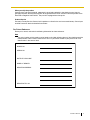
For Future Reference
Please print, record, and retain the following information for future reference.
Note
The serial number of this product can be found on the label affixed to the unit. You should record the
model number and the serial number of this unit as a permanent record of your purchase to aid in
identification in the event of theft.
MODEL NO.
SERIAL NO.
DATE OF PURCHASE
NAME OF DEALER
DEALER'S ADDRESS
DEALER'S TEL. NO.

10 Installation Manual
Introduction
This Installation Manual is designed to serve as an overall technical reference for the Panasonic Hybrid IP-
PBX, KX-TDA50. It provides instructions for installing the hardware, and programming the Hybrid IP-PBX
using the KX-TDA50 Maintenance Console.
The Structure of this Manual
This manual contains the following sections:
Section 1 System Outline
Provides general information on the Hybrid IP-PBX, including the system capacity and specifications.
Section 2 Installation
Describes the procedures to install the Hybrid IP-PBX. Detailed instructions for planning the installation
site, installing the optional service cards, and cabling of peripheral equipment are provided. Further
information on system expansion and peripheral equipment installation is included.
Section 3 Guide for the Hybrid IP-PBX PC Programming Software
Explains the installation procedure, structure, and basic information of the KX-TDA50 Maintenance
Console.
Section 4 Troubleshooting
Provides information on the Hybrid IP-PBX and telephone troubleshooting.
About the Other Manuals
Along with this Installation Manual, the following manuals are available:
Feature Manual
Describes all basic, optional and programmable features of the Hybrid IP-PBX.
PC Programming Manual
Provides step-by-step instructions for performing system programming using a PC.
PT Programming Manual
Provides step-by-step instructions for performing system programming using a PT.
Operating Manual
Provides operating instructions for end users using a PT, SLT, PS, or DSS Console.
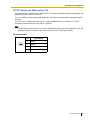
About the software version of your Hybrid IP-PBX
The contents of this manual apply to Hybrid IP-PBXs with a certain software version, as indicated on the
cover of this manual. To confirm the software version of your Hybrid IP-PBX, see "How do I confirm the
software version of the PBX or installed cards?" in the FAQ of the PC Programming Manual, or "[190] Main
Processing (MPR) Software Version Reference" in the PT Programming Manual.
Trademarks
• Microsoft and Windows are either registered trademarks or trademarks of Microsoft Corporation in
the United States and/or other countries.
• Intel and Celeron are trademarks or registered trademarks of Intel Corporation or its subsidiaries
in the United States and other countries.
• All other trademarks identified herein are the property of their respective owners.
• Screen shots reprinted with permission from Microsoft Corporation.

Installation Manual 11
F.C.C. REQUIREMENTS AND RELEVANT
INFORMATION
1. Notification to the Telephone Company
This equipment complies with Part 68 of the FCC rules and the requirements adopted by the ACTA. On
the side of this equipment is a label that contains, among other information, a product identifier in the
following format:
• US:AAAEQ##TXXXX
If requested, this number must be provided to the telephone company.
Installation must be performed by a qualified professional installer. If required, provide the telephone
company with the following technical information:
• Telephone numbers to which the system will be connected
• Make: Panasonic
• Model: KX-TDA50
• Certification No.: found on the side of the unit
• Ringer Equivalence No.: 0.3A
• Facility Interface Code: 02LS2
• Service Order Code: 9.0F
• Required Network Interface Jack: RJ11
2. Ringer Equivalence Number (REN)
The REN is used to determine the number of devices that may be connected to a telephone line.
Excessive RENs on a telephone line may result in the devices not ringing in response to an incoming
call. In most but not all areas, the sum of RENs should not exceed five (5.0). To be certain of the number
of devices that may be connected to a line, as determined by the total RENs, contact the local telephone
company. For products approved after July 23, 2001, the REN for this product is part of the product
identifier that has the following format:
• US:AAAEQ##TXXXX
The digits represented by ## are the REN without a decimal point (e.g., 03 is a REN of 0.3). For earlier
products, the REN is separately shown on the label.
3. Incidence of Harm to the Telephone Lines
If this equipment causes harm to the telephone network, the telephone company will notify you in
advance that temporary discontinuance of service may be required. But if advance notice isn't practical,
the telephone company will notify the customer as soon as possible. Also, you will be advised of your
right to file a complaint with the FCC if you believe it is necessary.
4. Changes in Telephone Company Communications Facilities, Equipment, Operations and
Procedures
The telephone company may make changes in its facilities, equipment, operations or procedures that
could affect the operation of the equipment. If this happens the telephone company will provide
advance notice in order for you to make necessary modifications to maintain uninterrupted service.
5. Trouble with this equipment
If trouble is experienced with this equipment, for repair or warranty information, please see the attached
warranty, which includes the Service Center Directory. If the equipment is causing harm to the
telephone network, the telephone company may request that you disconnect the equipment until the
problem is resolved.
6. Connection to Party Line
Connection to party line service is subject to state tariffs. Contact the state public utility commission,
public service commission or corporation commission for information.

12 Installation Manual
7. Combined Use with Alarm Equipment
If your home has specially wired alarm equipment connected to the telephone line, ensure the
installation of this equipment does not disable your alarm equipment. If you have questions about what
will disable alarm equipment, consult your telephone company or a qualified installer.
Note
This equipment has been tested and found to comply with the limits for a Class B digital device,
pursuant to Part 15 of the FCC Rules. These limits are designed to provide reasonable protection
against harmful interference in a residential installation. This equipment generates, uses, and can
radiate radio frequency energy and, if not installed and used in accordance with the instructions, may
cause harmful interference to radio communications. However, there is no guarantee that interference
will not occur in a particular installation. If this equipment does cause harmful interference to radio or
television reception, which can be determined by turning the equipment off and on, the user is
encouraged to try to correct the interference by one or more of the following measures:
• Reorient or relocate the receiving antenna.
• Increase the separation between the equipment and receiver.
• Connect the equipment into an outlet on a circuit different from that to which the receiver is
connected.
• Consult the dealer or an experienced radio/TV technician for help.
CAUTION
Any changes or modifications not expressly approved by the party responsible for compliance could
void the user's authority to operate this device.
When programming emergency numbers and/or making test calls to emergency numbers:
1. Remain on the line and briefly explain to the dispatcher the reason for the call before hanging up.
2. Perform such activities in the off-peak hours, such as early morning hours or late evenings.
WARNING
The software contained in the ARS and TRS features to allow user access to the
network must be upgraded to recognize newly established network area codes and
exchange codes as they are placed into service. Failure to upgrade the on-premise
PBXs or peripheral equipment to recognize the new codes as they are established will
restrict the customer and users of the PBX from gaining access to the network and to
these codes.
KEEP THE SOFTWARE UP TO DATE WITH THE LATEST DATA.

Installation Manual 13
For Cell Station
CAUTION
Any changes or modifications not expressly approved by the party responsible for compliance could
void user's authority to operate this device.
Note
This equipment has been tested and found to comply with the limits for a Class B digital device,
pursuant to Part 15 of the FCC Rules. These limits are designed to provide reasonable protection
against harmful interference in a residential installation. This equipment generates, uses, and can
radiate radio frequency energy and, if not installed and used in accordance with the instructions, may
cause harmful interference to radio communications. However, there is no guarantee that interference
will not occur in a particular installation. If this equipment does cause harmful interference to radio or
television reception, which can be determined by turning the equipment off and on, the user is
encouraged to try to correct the interference by one or more of the following measures:
• Reorient or relocate the receiving antenna.
• Increase the separation between the equipment and receiver.
• Connect the equipment into an outlet on a circuit different from that to which the receiver is
connected.
• Consult the dealer or an experienced radio/TV technician for help.
Some wireless telephones operate at frequencies that may cause interference to nearby TVs and
VCRs. To minimize or prevent such interference, the base of the wireless telephone should not be
placed near or on top of a TV or VCR. If interference is experienced, move the wireless telephone
further away from the TV or VCR. This will often reduce, or eliminate, interference.
Operating near 2.4 GHz electrical appliances may cause interference. Move away from the electrical
appliances.
CAUTION
To comply with FCC RF exposure requirements in uncontrolled environment:
• This equipment must be installed and operated in accordance with provided instructions and a
minimum 20 cm (8 in) spacing must be provided between antenna and all person's body (excluding
extremities of hands, wrist and feet) during wireless modes of operation.
• This transmitter must not be co-located or operated in conjunction with any other antenna or
transmitter.
Medical—consult the manufacturer of any personal medical devices, such as pacemakers, to
determine if they are adequately shielded from external RF (radio frequency) energy. (The unit operates
in the frequency range of 2401 MHz to 2480 MHz, and the power output level can range from 0.004 W
to 0.4 W.) Do not use the unit in health care facilities if any regulations posted in the area instruct you
not to do so. Hospitals or health care facilities may be using equipment that could be sensitive to
external RF (radio frequency) energy.

14 Installation Manual
Table of Contents
1 System Outline ..................................................................................... 17
1.1 System Highlights........................................................................................................... 18
1.1.1 System Highlights .............................................................................................................18
1.2 Basic System Construction ...........................................................................................20
1.2.1 Main Unit ...........................................................................................................................20
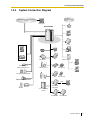
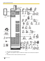
1.2.2 System Connection Diagram ............................................................................................21
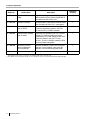
1.3 Optional Equipment........................................................................................................23
1.3.1 Optional Equipment ..........................................................................................................23
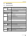
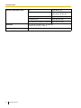
1.4 Specifications.................................................................................................................. 25
1.4.1 General Description ..........................................................................................................25
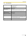
1.4.2 Characteristics ..................................................................................................................27
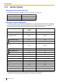
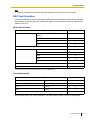
1.4.3 System Capacity ...............................................................................................................28
2 Installation............................................................................................. 31
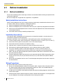
2.1 Before Installation...........................................................................................................32
2.1.1 Before Installation .............................................................................................................32
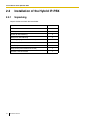
2.2 Installation of the Hybrid IP-PBX ...................................................................................34
2.2.1 Unpacking .........................................................................................................................34
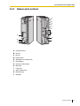
2.2.2 Names and Locations .......................................................................................................35
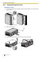
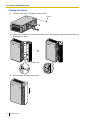
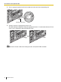
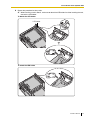
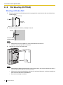
2.2.3 Opening/Closing the Covers .............................................................................................36
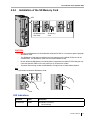
2.2.4 Installation of the SD Memory Card ..................................................................................39
2.2.5 Frame Ground Connection................................................................................................40
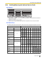
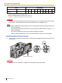
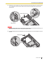
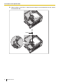
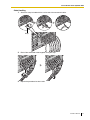
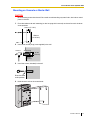
2.2.6 Installing/Removing the Optional Service Cards...............................................................41
2.2.7 Types of Connectors .........................................................................................................51
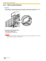
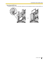
2.2.8 Wall Mounting (KX-TDA50) ...............................................................................................52
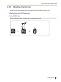
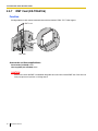
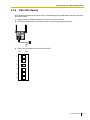
2.2.9 Attaching a Ferrite Core....................................................................................................55
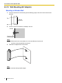
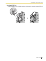
2.2.10 Wall Mounting (AC Adaptor)..............................................................................................56
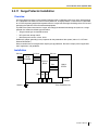
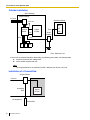
2.2.11 Surge Protector Installation...............................................................................................59
2.3 Information about the CO Line Cards ...........................................................................62
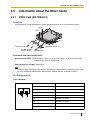
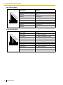
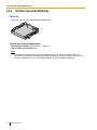
2.3.1 LCOT4 Card (KX-TDA5180) .............................................................................................62
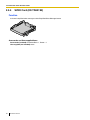
2.3.2 CID4 Card (KX-TDA5193).................................................................................................63
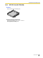
2.3.3 IP-GW4 Card (KX-TDA5480) ............................................................................................64
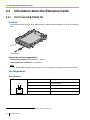
2.4 Information about the Extension Cards........................................................................66
2.4.1 HLC4 Card (KX-TDA5170)................................................................................................66
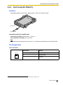
2.4.2 DLC4 Card (KX-TDA5171)................................................................................................67
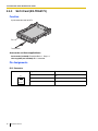
2.4.3 SLC4 Card (KX-TDA5173)................................................................................................68
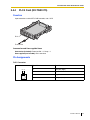
2.4.4 PLC4 Card (KX-TDA5175)................................................................................................69
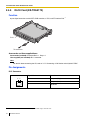
2.4.5 DLC8 Card (KX-TDA5172)................................................................................................70
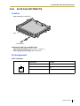
2.4.6 SLC8 Card (KX-TDA5174)................................................................................................71
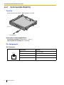
2.4.7 PLC8 Card (KX-TDA5176)................................................................................................72
2.4.8 IP-EXT4 Card (KX-TDA5470) ...........................................................................................73
2.5 Information about the Other Cards ...............................................................................75
2.5.1 DPH4 Card (KX-TDA5161) ...............................................................................................75
2.5.2 ECHO8 Card (KX-TDA5166) ............................................................................................78
2.5.3 MSG2 Card (KX-TDA5191)...............................................................................................79
2.5.4 SVM2 Card (KX-TDA5192) ...............................................................................................80
2.5.5 EXT-CID Card (KX-TDA5168) ...........................................................................................81

Installation Manual 15
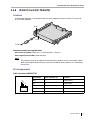
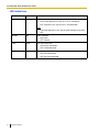
2.5.6 MEC Card (KX-TDA5105)................................................................................................. 82
2.5.7 RMT Card (KX-TDA5196)................................................................................................. 84
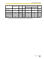
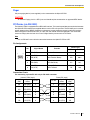
2.6 Connection of Extensions.............................................................................................. 86
2.6.1 Maximum Cabling Distances of the Extension Wiring (Twisted Cable)............................. 86
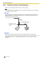
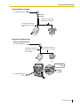
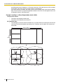
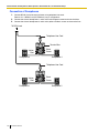
2.6.2 Parallel Connection of the Extensions .............................................................................. 88
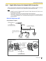
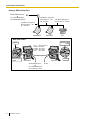
2.6.3 Digital EXtra Device Port (Digital XDP) Connection.......................................................... 91
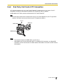
2.6.4 First Party Call Control CTI Connection............................................................................ 93
2.7 Connection of 2.4 GHz Portable Stations ..................................................................... 94
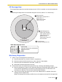
2.7.1 Overview ........................................................................................................................... 94
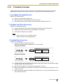
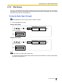
2.7.2 Procedure Overview .........................................................................................................95
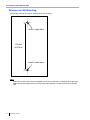
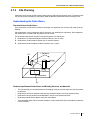
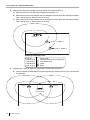
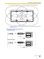
2.7.3 Site Planning..................................................................................................................... 97
2.7.4 Before Site Survey .......................................................................................................... 101
2.7.5 Site Survey...................................................................................................................... 103
2.7.6 After Site Survey ............................................................................................................. 107
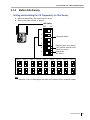
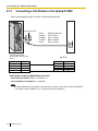
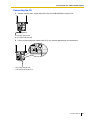
2.7.7 Connecting a Cell Station to the Hybrid IP-PBX ............................................................. 108
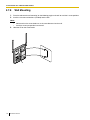
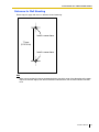
2.7.8 Wall Mounting ................................................................................................................. 114
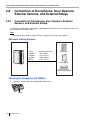
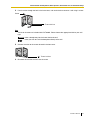
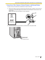
2.8 Connection of Doorphones, Door Openers, External Sensors, and External Relays ............ 116
2.8.1 Connection of Doorphones, Door Openers, External Sensors, and External Relays............. 116
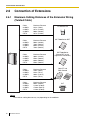
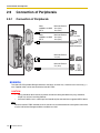
2.9 Connection of Peripherals ........................................................................................... 120
2.9.1 Connection of Peripherals............................................................................................... 120
2.10 Power Failure Connections.......................................................................................... 124
2.10.1 Power Failure Connections ............................................................................................. 124
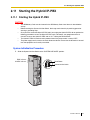
2.11 Starting the Hybrid IP-PBX .......................................................................................... 125
2.11.1 Starting the Hybrid IP-PBX ............................................................................................. 125
3 Guide for the Hybrid IP-PBX PC Programming Software ............... 129
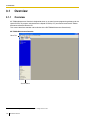
3.1 Overview ........................................................................................................................ 130
3.1.1 Overview ......................................................................................................................... 130
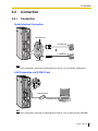
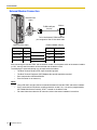
3.2 Connection .................................................................................................................... 131
3.2.1 Connection...................................................................................................................... 131
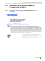
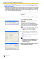
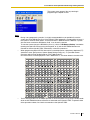
3.3 Installation of the Hybrid IP-PBX PC Programming Software .................................. 133
3.3.1 Installing and Starting the KX-TDA50 Maintenance Console ......................................... 133
4 Troubleshooting.................................................................................. 137
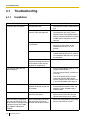
4.1 Troubleshooting............................................................................................................ 138
4.1.1 Installation....................................................................................................................... 138
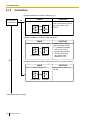
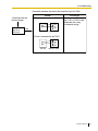
4.1.2 Connection...................................................................................................................... 140
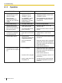
4.1.3 Operation ........................................................................................................................ 142
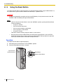
4.1.4 Using the Reset Button ................................................................................................... 144
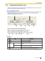
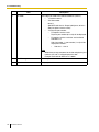
4.1.5 Troubleshooting by Error Log.......................................................................................... 145
5 Appendix ............................................................................................. 147
5.1 Revision History............................................................................................................ 148
5.1.1 PSMPR Software File Version 1.1xxx ............................................................................. 148
5.1.2 PSMPR Software File Version 2.0xxx ............................................................................. 149
5.1.3 PSMPR Software File Version 3.0xxx ............................................................................. 150
5.1.4 PSMPR Software File Version 4.0xxx ............................................................................. 151
Index .......................................................................................................... 153

16 Installation Manual

Installation Manual 17
Section 1
System Outline
This section provides general information on the Hybrid IP-
PBX, including the system capacity and specifications.

1.1 System Highlights
18 Installation Manual
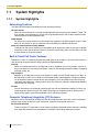
1.1 System Highlights
1.1.1 System Highlights
Networking Features
The Hybrid IP-PBX supports the following private networking features:
TIE Line Service
PBXs can be connected via a privately leased telephone lines forming a private network. These "TIE
lines" provide a cost-effective way to route calls and communications, and are often used to connect
corporate offices located in different cities.
QSIG Support
TIE line service can be used on a private network that implements the QSIG protocol (Q.931). QSIG
offers TIE line service as well as advanced caller and called party identification features.
Voice over Internet Protocol (VoIP) Network
The Hybrid-IP PBX can be used on a private network which implements VoIP. On this type of network,
information is sent over the private network in IP packets, which allows voice as well as data to be sent
to other devices in the private network.
Built-in Small Call Center Features
Extensions can form an incoming call distribution (ICD) group and be used as a small call center which can
take advantage of several features, some of which are highlighted below.
Queuing
When all available extensions in an ICD group are busy, additional calls can be placed in a queue as
they arrive. While calls are waiting in the queue, callers can hear background music (BGM), an outgoing
message (OGM), etc.
Log-in/Log-out
Members of an ICD group can log-in to or log-out of a group manually. Group members can log-in at
the beginning of a work shift, and log-out at the end of the day. While logged-in, ICD group members
can be allotted a specified amount of time after completing a call during which new calls will not be
received by their extensions, allowing them to finish any necessary paperwork before being eligible to
receive new calls (Wrap-up).
VIP Call
The VIP Call feature is one method of making sure that calls from preferred customers or callers are
answered quickly. When using VIP Call mode, ICD groups are assigned a priority, allowing calls in
higher-priority groups to be answered before calls in lower-priority groups.
Computer Telephony Integration (CTI) Features
Computers can be connected to the Hybrid-IP PBX to provide extension users with access to advanced
features such as pop-up display of caller information, computer-based speed dialing, etc.
PC Phone/PC Console
These Panasonic CTI applications can be used on computers connected to each extension, providing
their respective extension users with powerful and flexible call handling and display features.

1.1 System Highlights
Installation Manual 19
Third Party CTI Applications
The Hybrid IP-PBX supports industry standard protocols, allowing third-party CTI applications to be
integrated with the Hybrid-IP PBX and its extensions.
Voice Mail Features
A Voice Processing System (VPS) can be connected to the Hybrid IP-PBX to provide Voice Mail (VM) and
Automated Attendant (AA) services. A Panasonic VPS which supports DPT (Digital) Integration can be
connected to the Hybrid IP-PBX effortlessly and with minimal setup required. It can also be connected to
one Hybrid IP-PBX in a network to provide voice mail services for extensions at all Hybrid IP-PBXs.
Conventional DTMF (analog) voice mail systems, including those from other manufacturers, are also
supported.
Paralleled Telephone Features
By connecting telephones in parallel, you can increase the number of telephones connected to the Hybrid-
IP PBX without adding additional extension cards.
Parallel Mode
An SLT can be connected to an APT or DPT which is connected to a Super Hybrid Port of the Hybrid-
IP PBX. The SLT shares the same extension number with the APT or DPT.
EXtra Device Port (XDP) Mode
An SLT can be connected to a DPT which is connected to a Super Hybrid Port of the Hybrid-IP PBX.
Unlike parallel mode, XDP mode allows each telephone to act as an independent extension with its own
extension number.
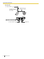
Digital XDP
A DPT can be connected to another DPT which is connected to a DPT port or a Super Hybrid Port of
the Hybrid-IP PBX. Similar to XDP mode, each DPT acts as an independent extension with its own
extension number.
Portable Station (PS) Features
A Panasonic PS can be used in place of a PT to provide wireless access to PBX features and call handling.
When in Wireless XDP Parallel Mode, a PS can share an extension number with a wired telephone, allowing
extension users to use their PSs when they are away from their desks to answer or make calls as if they
were using their wired telephones.
Hospitality Features
This Hybrid IP-PBX has several features that support its use in a hotel-type environment. Extensions
corresponding to guest rooms can be "checked in" or "checked out" by a designated hotel operator, who can
also check or set wake-up calls.
Simplified Voice Message (SVM) Features
By just installing an optional voice message card in the Hybrid IP-PBX, simple answering machine services
can be provided.

1.2 Basic System Construction
20 Installation Manual
1.2 Basic System Construction
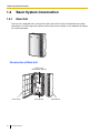
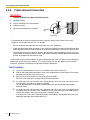
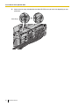
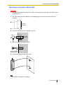
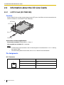
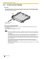
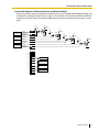
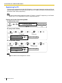
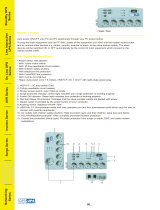
1.2.1 Main Unit
The main unit is equipped with 4 analog CO line ports (one LCOT4 card) and 4 extension ports (Super
Hybrid Ports). For system expansion, optional service cards can be installed, and an additional AC adaptor
can also be connected.
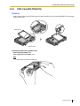
Construction of Main Unit
Main Board
LCOT4 card
(installed by default)
Front Cover Cable Cover
Page is loading ...
Page is loading ...
Page is loading ...
Page is loading ...
Page is loading ...
Page is loading ...
Page is loading ...
Page is loading ...
Page is loading ...
Page is loading ...
Page is loading ...
Page is loading ...
Page is loading ...
Page is loading ...
Page is loading ...
Page is loading ...
Page is loading ...
Page is loading ...
Page is loading ...
Page is loading ...
Page is loading ...
Page is loading ...
Page is loading ...
Page is loading ...
Page is loading ...
Page is loading ...
Page is loading ...
Page is loading ...
Page is loading ...
Page is loading ...
Page is loading ...
Page is loading ...
Page is loading ...
Page is loading ...
Page is loading ...
Page is loading ...
Page is loading ...
Page is loading ...
Page is loading ...
Page is loading ...
Page is loading ...
Page is loading ...
Page is loading ...
Page is loading ...
Page is loading ...
Page is loading ...
Page is loading ...
Page is loading ...
Page is loading ...
Page is loading ...
Page is loading ...
Page is loading ...
Page is loading ...
Page is loading ...
Page is loading ...
Page is loading ...
Page is loading ...
Page is loading ...
Page is loading ...
Page is loading ...
Page is loading ...
Page is loading ...
Page is loading ...
Page is loading ...
Page is loading ...
Page is loading ...
Page is loading ...
Page is loading ...
Page is loading ...
Page is loading ...
Page is loading ...
Page is loading ...
Page is loading ...
Page is loading ...
Page is loading ...
Page is loading ...
Page is loading ...
Page is loading ...
Page is loading ...
Page is loading ...
Page is loading ...
Page is loading ...
Page is loading ...
Page is loading ...
Page is loading ...
Page is loading ...
Page is loading ...
Page is loading ...
Page is loading ...
Page is loading ...
Page is loading ...
Page is loading ...
Page is loading ...
Page is loading ...
Page is loading ...
Page is loading ...
Page is loading ...
Page is loading ...
Page is loading ...
Page is loading ...
Page is loading ...
Page is loading ...
Page is loading ...
Page is loading ...
Page is loading ...
Page is loading ...
Page is loading ...
Page is loading ...
Page is loading ...
Page is loading ...
Page is loading ...
Page is loading ...
Page is loading ...
Page is loading ...
Page is loading ...
Page is loading ...
Page is loading ...
Page is loading ...
Page is loading ...
Page is loading ...
Page is loading ...
Page is loading ...
Page is loading ...
Page is loading ...
Page is loading ...
Page is loading ...
Page is loading ...
Page is loading ...
Page is loading ...
Page is loading ...
Page is loading ...
Page is loading ...
Page is loading ...
Page is loading ...
Page is loading ...
Page is loading ...
Page is loading ...
Page is loading ...
-
 1
1
-
 2
2
-
 3
3
-
 4
4
-
 5
5
-
 6
6
-
 7
7
-
 8
8
-
 9
9
-
 10
10
-
 11
11
-
 12
12
-
 13
13
-
 14
14
-
 15
15
-
 16
16
-
 17
17
-
 18
18
-
 19
19
-
 20
20
-
 21
21
-
 22
22
-
 23
23
-
 24
24
-
 25
25
-
 26
26
-
 27
27
-
 28
28
-
 29
29
-
 30
30
-
 31
31
-
 32
32
-
 33
33
-
 34
34
-
 35
35
-
 36
36
-
 37
37
-
 38
38
-
 39
39
-
 40
40
-
 41
41
-
 42
42
-
 43
43
-
 44
44
-
 45
45
-
 46
46
-
 47
47
-
 48
48
-
 49
49
-
 50
50
-
 51
51
-
 52
52
-
 53
53
-
 54
54
-
 55
55
-
 56
56
-
 57
57
-
 58
58
-
 59
59
-
 60
60
-
 61
61
-
 62
62
-
 63
63
-
 64
64
-
 65
65
-
 66
66
-
 67
67
-
 68
68
-
 69
69
-
 70
70
-
 71
71
-
 72
72
-
 73
73
-
 74
74
-
 75
75
-
 76
76
-
 77
77
-
 78
78
-
 79
79
-
 80
80
-
 81
81
-
 82
82
-
 83
83
-
 84
84
-
 85
85
-
 86
86
-
 87
87
-
 88
88
-
 89
89
-
 90
90
-
 91
91
-
 92
92
-
 93
93
-
 94
94
-
 95
95
-
 96
96
-
 97
97
-
 98
98
-
 99
99
-
 100
100
-
 101
101
-
 102
102
-
 103
103
-
 104
104
-
 105
105
-
 106
106
-
 107
107
-
 108
108
-
 109
109
-
 110
110
-
 111
111
-
 112
112
-
 113
113
-
 114
114
-
 115
115
-
 116
116
-
 117
117
-
 118
118
-
 119
119
-
 120
120
-
 121
121
-
 122
122
-
 123
123
-
 124
124
-
 125
125
-
 126
126
-
 127
127
-
 128
128
-
 129
129
-
 130
130
-
 131
131
-
 132
132
-
 133
133
-
 134
134
-
 135
135
-
 136
136
-
 137
137
-
 138
138
-
 139
139
-
 140
140
-
 141
141
-
 142
142
-
 143
143
-
 144
144
-
 145
145
-
 146
146
-
 147
147
-
 148
148
-
 149
149
-
 150
150
-
 151
151
-
 152
152
-
 153
153
-
 154
154
-
 155
155
-
 156
156
-
 157
157
-
 158
158


Panasonic KX-TDA50 User manual
- Type
- User manual
- This manual is also suitable for
Ask a question and I''ll find the answer in the document
Finding information in a document is now easier with AI
Related papers
-
Panasonic KX-TDA50 User manual
-
-
-
Philips KX-TAW84868 - Extension Caller Id Card User manual
-
Panasonic KX-TDA30 User manual
-
Panasonic KX-NS1000 Pc Programming Manual
-
-
-
-
Other documents
-
RTS XCP-40-RJ11 User manual
-
Siemens SLT-1-UK Upgrade Kit User manual
-
SBS SP3120T Datasheet
-
Euri Lighting DLC4S-2000e Installation guide
-
 OPTI-UPS Green Power Series Master / Slave User manual
-
 XDP Recreation Camo Commander Assembly, Care & Maintenance Manual
-
 Algo 3226 User guide
-
DLS HLC4 Owner's manual
-
Life Fitness M051-00K32-A086 User manual
-
Lucent Technologies MERLIN LEGEND Release 5.0 System Programming Manual


