
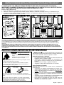
INSTALLATION AND SERVICE MUST BE PERFORMED BY A QUALIFIED INSTALLER.
IMPORTANT: SAVE FOR LOCAL ELECTRICAL INSPECTOR'S USE.
READ AND SAVE THESE INSTRUCTIONS FOR FUTURE REFERENCE.
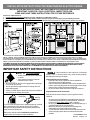
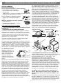
Clearances and Dimensions
1.
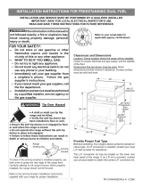
Provide adequate clearances between the range and adjacent combustible surfaces.
2. Location—Check location where the range will be installed. Check for proper electrical supply, and the stability of the floor.
3. Dimensions that are shown must be used. Given dimensions provide minimum clearance. Contact surface must be solid and level.
*30" MINIMUM CLEARANCE BETWEEN THE TOP OF THE COOKING SURFACE AND THE BOTTOM OF AN UNPROTECTED WOOD OR
METAL CABINET; OR 24" MINIMUM WHEN BOTTOM OF WOOD OR METAL CABINET IS PROTECTED BY NOT LESS THAN 1/4" FLAME
RETARDANT MILLBOARD COVERED WITH NOT LESS THAN NO. 28 MSG SHEET STEEL, 0.015" STAINLESS STEEL, 0.024" ALUMINUM OR
0.020" COPPER. 0" CLEARANCE IS THE MINIMUM FOR THE REAR OF THE RANGE. FOLLOW ALL DIMENSION REQUIREMENTS PROVIDED
ABOVE TO PREVENT PROPERTY DAMAGE, POTENTIAL FIRE HAZARD, AND INCORRECT COUNTERTOP AND CABINET CUTS.
TO ELIMINATE THE RISK OF BURNS OR FIRE BY REACHING OVER HEATED SURFACE UNITS, CABINET STORAGE SPACE LOCATED ABOVE
THE SURFACE UNITS SHOULD BE AVOIDED. IF CABINET STORAGE IS TO BE PROVIDED, THE RISK CAN BE REDUCED BY INSTALLING A
RANGE HOOD THAT PROJECTS HORIZONTALLY A MINIMUM OF 5" BEYOND THE BOTTOM OF THE CABINETS.
p/n 316454912 rev C
Fig. 1
Fig. 2
Fig. 3
30"
Important Notes to the Consumer:
Keep these instructions with your owner's guide for future
reference.
• As when using any appliance generating heat, there are
certain safety precautions you should follow. These are
listed in the Use & Care Guide, read it carefully.
• Be sure your range is installed and grounded properly by a
qualified installer or service technician.
• Make sure the wall coverings around the range can
withstand the heat generated by the range.
• To eliminate the need to reach over the surface elements,
cabinet storage space above the elements should be
avoided.
IMPORTANT SAFETY INSTRUCTIONS
INSTALLATION INSTRUCTIONS FOR FREESTANDING ELECTRIC RANGE
1
Español - Páginas 5-8
25-3/4”
49”
48”
29 1/4” with
door handle
maximum
door open
maximum
• Ensure the anti-tip device is re-engaged when the range
is moved to floor or wall.
• Do not operate the range without the anti-tip device in
place and engaged.
• Failure to follow these instructions can result in death or
serious burns to children and adults.
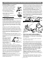
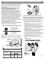
Tip Over Hazard
To check if the anti-tip bracket is installed properly, use both
arms and grasp the rear edge of range back. Carefully
attempt to tilt range forward. When properly installed, the
range should not tilt forward.
Refer to the anti-tip bracket installation instructions
supplied with your range for proper installation.
Range
leveling leg
Anti-Tip
bracket
• A child or adult can tip the range and
be killed.
• Verify the anti-tip device has been
installed to floor or wall.
If the information in this manual is not followed
exactly, a fire or electrical shock may result causing property
damage, personal injury or death.
Important Notes to the Installer:
• Read all instructions contained in these installation
instructions before installing range.
• Remove all packing material from the oven compartments
before connecting the gas & electrical supply to the range.
• Observe all governing codes and ordinances.
• Be sure to leave these instructions with the consumer.

2. ELECTRICAL CONNECTION REQUIREMENTS - This
appliance must be properly installed and grounded by a
qualified technician in accordance with the National Electrical
Code ANSI/NFPA No. 70 -- latest edition -- and Local Electrical
Code requirements.
This appliance may be connected by means of "permanent
wiring" or power supply cord kit."
When installing permanent wiring, do not leave excess wire in
range compartment. Excess wire in the range compartment
may not allow the rear access cover to be replaced properly
and could create a potential electrical hazard if wires become
pinched. Connect only as instructed under "Permanent Wire
Connections" in Step 4c. When using flexible conduit or range
cable use flex connector or range cable strain relief (Fig. 11).
Fig. 4
Fig. 5
Fig. 6
Fig. 7
Mobile home installations, new branch circuit installations
(1996NEC) or areas where local codes do not permit
grounding through neutral require a four (4) conductor power
supply cord kit rated at 125/250 volts minimum and marked for
use with ranges.
See range connection opening size chart (Figs. 9 & 10) for
cord kit ampere rating information. Terminals on end of wires
must be either closed loop or open-end spade lugs with
upturned ends.
2
INSTALLATION INSTRUCTIONS FOR FREESTANDING ELECTRIC RANGE
BEFORE STARTING - Tools You Will Need
For leveling legs and Anti-Tip Bracket:
• Adjustable wrench or channel lock pliers
• 5/16" Nutdriver or Flat Head Screwdriver
• Electric Drill & 1/8" Diameter Drill Bit
(Masonry Drill Bit if installing in concrete)
For electrical supply connection:
• 1/4" & 3/8" Socket driver or Nutdriver
Additional Materials You Will Need:
• Power Supply Cord or
• Copper Electrical Wiring & Metal Conduit
(for hard wiring)
NORMAL INSTALLATION STEPS
1. ANTI-TIP BRACKET INSTALLATION INSTRUCTIONS -
IMPORTANT SAFETY WARNING
To reduce the risk of tipping of the range, the range must be
secured to the floor by properly installed Anti-Tip Bracket and
screws packed with the range. Failure to install the anti-tip
bracket will allow the range to tip over if excessive weight is
placed on an open door or if a child climbs upon it. Serious
injury might result from spilled hot liquids or from the range
itself.
If range is ever moved to a different location, the Anti-Tip
Bracket must also be moved and installed with the range.
Instructions are provided for installation in wood or cement
fastened to either the floor or wall. When installed to the wall,
make sure that screws completely penetrate dry wall and are
secured in wood or metal. When fastening to the floor or wall,
be sure that screws do not penetrate electrical wiring or
plumbing.
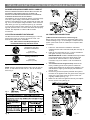
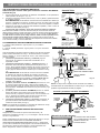
1a. Locate the Bracket using the Template - (Bracket
may be located on either the left or right side of the range. Use
the information below to locate the bracket if template is not
available).
Mark the floor or wall where
left or right side of the range
will be located. If rear of
range is against the wall or
no further than 1-1/4" from
wall when installed, you may
use the wall or floor mount
method. If molding is
installed and does not allow
the bracket to fit flush against the wall, remove molding or
mount bracket to the floor. For wall mount, locate the bracket by
placing the back edge of the template against the rear wall and
the side edge of template on the mark made referencing the
side of the range (See Fig. 4). Place bracket on top of template
and mark location of the screw holes in wall. If rear of range is
further than 1-1/4" from the wall when installed, attach bracket
to the floor. For floor mount, locate the bracket by placing back
edge of the template where the rear of the range will be
located. Mark the location of the screw holes, shown in
template.
1b. Drill Pilot Holes & Fasten Bracket - Drill a 1/8" pilot
hole where screws are to be located. If bracket is to be
mounted to the wall, drill pilot hole at an approximate 20°
downward angle (See Fig. 5).
If bracket is to be mounted to masonry or ceramic floors, drill a
3/16" pilot hole 1-3/4" deep. The screws provided may be used
in wood or concrete material. Use a 5/16" nut-driver or flat
head screwdriver to secure the bracket in place (See Fig. 6).
1c. Level and Position Range - Level range by adjusting
the (4) leveling legs with a wrench. Note: A minimum
clearance of 1/8" is required between the bottom of the range
and the leveling leg to allow room for the bracket. Use a spirit
level to check your adjustments. Slide range back into position
(See Fig. 7). Visually check that rear leveling leg is inserted
into and fully secured by the Anti-Tip Bracket by removing lower
panel or storage drawer. For models with a Warmer Drawer or
broiler compartment, grasp the top rear edge of the range and
carefully attempt to tilt it forward.
2a. Models with factory connected power supply cord.
NOTE: Some models may have a factory installed
three (3) conductor power supply cord.

2b. MODELS REQUIRING POWER SUPPLY CORD KIT.
RISK OF FIRE OR ELECTRICAL SHOCK MAY OCCUR IF AN
INCORRECT SIZE RANGE CORD KIT IS USED, THE
INSTALLATION INSTRUCTIONS ARE NOT FOLLOWED OR
STRAIN RELIEF BRACKET IS DISCARDED.
This appliance may be connected by means of a power supply
cord. Only a power supply cord kit rated at 125/250 volts
minimum, and marked for use with ranges shall be used. See
Fig. 10 for cord kit ampere rating information. Cord must have
either three (3) or four (4) conductors (See Fig. 8). Terminals
on end of wires must be either closed loop or open-end spade
lugs with upturned ends. Cord must have strain relief properly
installed. See Steps 4a. for 4-Wire or 4b. for 3-Wire
connections.
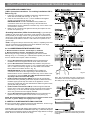
3. ELECTRICAL CONNECTION TO RANGE.
The Rear Access Cover must be removed (Fig 9). To remove,
loosen center screw (one screw) and remove cover. The
terminal block will then be accessible.
Fig. 10
4A. POWER CORD CONNECTIONS
Fig. 11
Fig. 12
(4-Wire Connection Instructions - Refer to Fig.12)
Before wiring the range review the suggested power source
location drawing in Fig. 3. If connecting to a 4-Wire electrical
system (new branch-circuit or mobile home requires 4-Wire
connection):
1. Follow the manufacturer’s installation instructions
supplied with the strain relief and install (Also see Figs. 9,
10 & 11).
2. Insert the end connectors for Line 1, Line 2 and Neutral
and tighten securely to the terminal block.
IMPORTANT NOTE: DO NOT LOOSEN the factory installed
nut connections which secure the range wiring to the
terminal block. Electrical failure or loss of electrical
connection may occur if these 3 nuts are loosened or
removed.
3. You must disconnect the ground strap. Remove the
factory installed ground screw & plate to release the
copper ground strap from the frame of the appliance. Cut
and discard the copper ground strap & plate. KEEP the
ground screw.
4. Connect the ground wire (Green) lead with the eyelet to
the frame of the appliance with the ground screw using the
same hole in the frame where the ground screw was
originally installed (See Fig. 12).
5. Make sure all screws are tightened securely and replace
the rear access cover (See Fig. 9).
3
INSTALLATION INSTRUCTIONS FOR FREESTANDING ELECTRIC RANGE
NOTE: Range is shipped from factory with 1-3/8" dia. hole as
shown. To use either 7/8" dia. hole or 1-1/8" dia. knockouts
refer to Fig. 9.
Fig. 8
Fig. 9
Rear
Access
Cover
3 & 4 - Wire electrical wall Receptacle types &
recommended mounting orientation on wall
Required for new and
remodeled installations
4-Wire Wall
receptacle (14-50R)
Allowed for
existing installations
3 Wire Wall
receptacle (10-50R)

or 4B. POWER CORD CONNECTIONS
(3-Wire Connection Instructions . For existing installations ONLY -
Refer to Fig. 13).
1. Follow the manufacturer’s installation instructions supplied with the
strain relief and install (Also see Figs. 9, 10 & 11).
2. Insert the end connectors for Line 1, Line 2 and Neutral and tighten
securely to the terminal block (See Fig. 13).
IMPORTANT NOTE: DO NOT LOOSEN the factory installed nut
connections which secure the range wiring to the terminal block.
Electrical failure or loss of electrical connection may occur if these 3 nuts
are loosened or removed.
3. Make sure all connections are tightened securely and replace the rear
access cover (See Fig. 9).
Grounding Instructions (3-Wire Connections only): A ground strap is
installed on this range which connects the center terminal of the terminal
block (Neutral) to the range chassis. The ground strap is connected to the
range by the center, lowest screw (See Fig. 13). The ground strap must not
be removed unless National, State or Local Codes do not permit use of a
ground strap.
NOTE: If the ground strap is removed for any reason, a separate ground wire
must be connected to the separate ground screw attached to the range
chassis and to an adequate ground source.
NOTE: Non-terminated field wire compression connections must be set at
22 in./lbs. or greater. Always use 10 gauge wire or larger.
Fig. 13
4c. 3 & 4-WIRE PERMANENT WIRE CONNECTIONS.
3 - Wire Permanent Connection - follow Steps 1,2 & 5 below.
4 - Wire Permanent Connection - follow Steps 1 thru 5 below.
Before wiring the range, review the suggested power source location
drawings in Fig. 3. If connecting to a 4-Wire electrical system (new branch-
circuit or mobile home requires 4-Wire connection):
1. (3 & 4 - Wire Permanent Connections) Follow the manufacturer’s
installation instructions supplied with the strain relief and install.
2. (3 & 4 - Wire Permanent Connections) Strip insulation away from the
ends of the permanent wiring for Line 1, Line 2, Neutral (also strip ground
wire on 4-Wire Connections). Tighten all 3 wire leads to the terminal
block (Follow wire locations shown in Fig. 14).
IMPORTANT NOTE: DO NOT LOOSEN the factory installed nut
connections which secure the range wiring to the terminal block.
Electrical failure or loss of electrical connection may occur if these 3 nuts
are loosened or removed. NOTE: For 3-Wire Permanent Connections
skip Steps 3 & 4 and continue with Step 5.
3. (4-Wire Permanent Connection ONLY) Disconnect the ground strap.
Remove the factory installed ground screw & plate to release the factory
installed copper ground strap from frame of the appliance. Cut and
discard the copper strap from the terminal block. KEEP the ground screw,
ground plate and go to Step 4.
4. (4-Wire Permanent Connection ONLY) Connect the ground wire lead
(Green) to the frame of the appliance using the ground screw & plate as
shown in Fig. 15. Be sure to install using the same hole in the frame
where the ground screw was originally installed.
5. (3 & 4 - Wire Permanent Connections) Make sure all connections are
tightened securely and replace the rear access cover (See Fig. 9).
Fig. 14
5. CAREFULLY SLIDE RANGE INTO FINAL LOCATION.
Be sure to provide all the adequate clearances and dimensions shown in Figs.
1, 2 & 3 before moving appliance into final location.
Carefully slide range into final position while inserting rear leveling leg into and
FULLY ENGAGING THE ANTI-TIP BRACKET (See Fig. 7). Make sure the power
cord folds into the remaining open floor area behind the range Warmer or storage
drawer. Be sure to check the level of the range.
Fig. 15
4
INSTALLATION INSTRUCTIONS FOR FREESTANDING ELECTRIC RANGE
Note: Non-terminated field wire compression
connections must be set at approximately 22in./
lbs. Always use 10 ga. wire or larger.
Serial plate is located on the lower right front frame
of the appliance. Alternate location may be under
cooktop.
Serial Plate Locations:

5
LA INSTALACION Y EL SERVICIO DEBEN SER EFECTUADOS POR UN INSTALADOR CALIFICADO.
IMPORTANTE: CONSERVE ESTAS INSTRUCCIONES PARA USO DEL INSPECTOR LOCAL DE ELECTRICIDAD.
LEA Y CONSERVE ESTAS INSTRUCCIONES PARA REFERENCIA FUTURA.
Espacios Libres y Dimensiones
1. Provea espacios libres adecuados entre la estufa y las superficies combustibles adyacentes.
2. Ubicación – Revise el lugar donde será instalada la estufa. Verifique el suministro de energía eléctrica y la estabilidad del piso.
3. Es esencial que se usen las dimensiones que se muestran. Las dimensiones indicadas proveen los espacios libres mínimos. La
superficie de contacto debe ser firme y nivelada.
*ESPACIO LIBRE MINIMO DE 30" ENTRE LA CUBIERTA DE COCINAR DE LA ESTUFA Y LA PARTE INFERIOR DE UN ARMARIO DE METAL O DE MADERA NO
PROTEGIDO; O 24" MINIMO CUANDO LA PARTE INFERIOR DE UN ARMARIO DE METAL O DE MADERA ESTA PROTEGIDA CON CARTON RETARDANTE A
LAS LLAMAS DE NO MENOS DE 1/4" CUBIERTO CON CHAPA DE ACERO NO INFERIOR AL No. 28 MSG, ACERO INOXIDABLE DE 0.015", ALUMINO DE
0.024" O COBRE DE 0.020". EL ESPACIO LIBRE DE 0" ES EL MINIMO PARA LA PARTE TRASERA DE LA ESTUFA. SIGA TODAS LAS DIMENSIONES
INDICADAS ANTERIORMENTE PARA EVITAR DAÑOS MATERIALES, RIESGOS DE INCENDIO Y CORTES INCORRECTOS DE LOS ARMARIOS Y DE LAS
MESADAS.
PARA ELIMINAR EL RIESGO DE QUEMADURAS O INCENDIOS AL PASAR SOBRE LOS ELEMENTOS CALIENTES, SE DEBE EVITAR COLOCAR
ARMARIOS DE ALMACENAMIENTO SOBRE LA ESTUFA. SI SE INSTALAN ARMARIOS SOBRE LA ESTUFA, SE PUEDEN REDUCIR TALES RIESGOS
INSTALANDO UNA CAMPANA EXTRACTORA QUE SE PROYECTE HORIZONTALMENTE UN MINIMO DE 5" MAS AFUERA DE LA PARTE INFERIOR DE
LOS ARMARIOS.
English - Pages 1-4
Fig. 1
Fig. 2
Fig. 3
30"
INSTRUCCIONES IMPORTANTES DE SEGURIDAD
Aviso importante al consumidor
Mantenga estas instrucciones con su Guía de Uso y Cuidado para
referencia futura.
• Al igual que con cualquier electrodoméstico que genere calor,
existen ciertas precauciones de seguridad que usted debe
seguir. Tales precauciones se encuentran en la
Guía de Uso y
Cuidado, léala atentamente.
• Asegúrese de que la estufa esté bien instalada y sea puesta a
tierra en forma debida por un instalador calificado o un técnico de
servicio.
• Asegúrese de que el revestimiento de la pared alrededor de la
estufa pueda resistir el calor generado por la estufa.
• Para eliminar la necesidad de tener que pasar sobre los
elementos, se recomienda no instalar armarios arriba los
elementos de la cubierta de la estufa.
INSTRUCCIONES DE INSTALACION PARA LA ESTUFA ELECTRICA DE 30"
Si no se sigue estrictamente la información de
este manual, se puede producir un incendio o un choque eléctrico que
cause daños materiales, lesiones corporales o fatales.
Notas Importantes para el Instalador
• Lea todas las instrucciones indicadas en estas instrucciones de
instalación antes de instalar la estufa.
• Saque todo el material de empaque del compartimiento del
horno antes de conectar el suministro de gas y de electricidad a
la estufa.
• Observe todos los códigos y reglamentos vigentes.
• Asegúrese de dejar estas instrucciones con el usuario.
• Asegúrese de que el dispositivo antivuelco se haya reacoplado cuando
mueva la estufa sobre el piso o a la pared.
• No utilice la estufa sin el dispositivo antivuelco instalado y acoplado.
• Si no se siguen estas instrucciones, se puede provocar la muerte o
quemaduras graves en niños y adultos.
Para verificar si el soporte antivuelco está instalado correctamente,
sostenga el borde trasero de la parte trasera de la estufa usando ambos
brazos.
Intente inclinar la estufa hacia adelante con cuidado. Si está instalada
correctamente, la estufa no debería inclinarse hacia adelante. Consulte
las instrucciones de instalación del soporte antivuelco
proporcionadas con la estufa para instalarlo adecuadamente.
WARNING:
Riesgo de volcamiento
• Un niño o adulto puede volcar la estufa y acabar
muerto.
• Verifique que se haya instalado el dispositivo
antivuelco en el piso o en la pared.
Tornillo nivelador
de la estufa
Soporte
antivuelco

6
Fig. 7
Costado
de la
estufa
11/16"
Deslice la
estufa
hacia atrás
ANTES DE COMENZAR
Herramientas Necesarias
Para los tornillos niveladores y soporte antivuelco:
• Llave ajustable o pinzas ajustables
• Llave de tuerca de 5/16" o destornillador
de punta plana
• Taladro eléctrico y broca de 1/8" de diám. (broca para taladro de
mampostería si está instalando en concreto)
Para la conexión al suministro eléctrico:
• Llave de cubo o llave para tuercas de ¼”
y 3/8"
Materiales adicionales que usted necesitará:
• Cordón eléctrico o
• Cableado eléctrico de cobre y conducto
de metal (para el cableado)
PASOS DE LA INSTALACION NORMAL
1. INSTRUCCIONES PARA LA INSTALACION DEL SOPORTE
ANTIVUELCO
- ADVERTENCIA DE SEGURIDAD IMPORTANTE
Para reducir el riesgo de que la estufa se vuelque, es necesario
asegurarla al piso instalando el soporte antivuelco y los tornillos
suministrados con la estufa. Si no se instala el soporte antivuelco,
la estufa se puede volcar si un niño se sube a ella. Se pueden
ocasionar lesiones graves causadas por los líquidos calientes
derramados o por la estufa misma.
Si la estufa es movida a otro lugar, el soporte antivuelco debe
también ser movido e instalado en la estufa.
Las instrucciones son adecuadas para la instalación en pisos de
madera o cemento sujeto ya sea en el piso o en la pared. Cuando
se instala en la pared, asegúrese de que los tornillos penetren
completamente en la misma y que estén asegurados en madera
o metal. Cuando se asegura al piso o en la pared, asegúrese de
que los tornillos no penetren ningún cableado eléctrico o plomería.
Fig. 4
Fig. 5
Fig. 6
INSTALACIÓN DEL SOPORTE
(MONTAJE EN LA PARED O EN EL PISO)
INSTALACIÓN DEL SOPORTE
(MONTAJEENEL PISO SOLAMENTE)
Tornillo
nivelador
Tornillo
nivelador
Máx.
1-1/4"
Más de
1-1/4"
Montaje en
la pared
Placa
mural
Montaje en
el piso
Montaje en
el piso
Soporte
antivuelco
Soporte
antivuelco
Pared
Parte trasera
de la estufa
Parte trasera
de la estufa
INSTRUCCIONES DE INSTALACION PARA LA ESTUFA ELECTRICA DE 30"
1b. Taladre agujeros pilotos e instale el soporte - Taladre un
agujero piloto de 1/8" donde se vayan a instalar los tornillos. Si el
soporte va a ser instalado en la pared, taladre un agujero piloto en un
ángulo descente de aproximadamente 20° (Ver Fig. 5).
Si el soporte va a ser instalado en pisos de mampostería o de
cerámica, taladre un agujero piloto de 3/16" y 1-3/4" de profundidad.
Los tornillos provistos pueden ser usados en materiales de madera
o concreto. Use una llave de tuerca de 5/16" o un destornillador de
punta plana para asegurar el soporte en su lugar (Ver Fig. 6).
1c. Nivele y ubique la estufa – Nivele la estufa ajustando los
cuatro (4) tornillos niveladores con una llave. NOTA: Se debe dejar un
espacio libre mínimo de 1/8" entre la parte inferior de la estufa y los
tornillos niveladores a fin de dejar espacio para instalar el soporte.
Use un nivel de burbuja de aire para verificar los ajustes. Deslice la
estufa de nuevo a su lugar (Ver Fig. 7). Verifique visualmente si el
tornillo nivelador trasero está insertado y firmemente asegurado por
el soporte antivuelco retirando el panel inferior o la gaveta de
almacenamiento. Para los modelos con una gaveta calentadora o
compartimiento asador, sujete la estufa desde el borde superior
trasero y trate de inclinarla hacia adelante cuidadosamente.
1a. Ubicación del soporte
utilizando la plantilla
- (El
soporte puede ser ubicado ya
sea en el lado izquierdo o
derecho de la estufa. Use la
información indicada a
continuación para colocar el
soporte si no se dispone de la
plantilla.
Marque el piso o la pared donde se colocará el costado izquierdo o
derecho de la estufa. Si la parte trasera de la estufa será colocada
contra la pared o a no más de 1-1/4" de la pared cuando ya esté
instalada, usted puede usar el método de instalación en el piso o en
la pared. Si tiene moldura instalada y ésta no permite que el soporte
quede a ras contra la pared, retire la moldura o instale el soporte en
el piso. Para el montaje en la pared, ubique la plantilla colocando el
borde trasero de la plantilla contra la pared trasera y el borde lateral
de la plantilla en la marca hecha indicando el costado de la estufa
(Ver Fig. 4). Coloque el soporte sobre la plantilla y marque la
ubicación de los agujeros de los tornillos en la pared. Si la parte
trasera de la estufa está a más de 1-1/4" de la pared cuando ya está
instalada, instale el soporte en el piso. Para el montaje en el piso,
ubique el soporte colocando el borde trasero de la plantilla donde
quedará ubicada la parte trasera de la estufa. Marque la ubicación de
los agujeros de los tornillos mostrados en la plantilla.
2. REQUERIMIENTOS ELECTRICOS DE CONEXION - Este
artefacto debe ser instalado y puesto a tierra en forma correcta por
un técnico calificado de acuerdo con el Código Nacional de
Electricidad ANSI/NFPA No. 70 -- última edición -- y los
requerimientos del código local de electricidad.
Este artefacto debe ser conectado mediante “cableado
permanente” o el “Juego de Cable de Alimentación Eléctrica.”
Cuando instale el cableado permanente, no deje el exceso de
cable en el compartimiento de la estufa. El exceso de cable en el
compartimiento de la estufa puede impedir que la tapa de acceso
sea reinstalada en forma debida y podría crear un riesgo eléctrico
potencial si los alambres son apretados. Conecte solamente
como se indica en la sección “CONEXIONES DEL CABLEADO
PERMANENTE” en el Paso 4c. Cuando use tubo flexible o cable
de estufa, use un sujetacable o conector flexible (Ver Fig. 11).
2a. Modelos con el cordón eléctrico conectado en la
fábrica. NOTA: Algunos modelos vienen equipados con
cordón eléctrico de tres (3) conductores instalado en la
fábrica.
La instalación en casas rodantes, en instalaciones de circuitos de
derivación (1996NEC) o en áreas donde los códigos locales no
permitan la puesta a tierra a través del conductor neutro, se debe
usar un juego de cordón eléctrico de cuatro (4) conductores para
125/250 voltios mínimo y marcado para uso con estufas.

7
NOTA: La estufa es embarcada de la fábrica con un agujero de 1-
3/8" de diámetro como se muestra. Para usar ya sea el agujero de
7/8" de diámetro o los discos removibles de 1-1/8" de diámetro.
Ver la Fig. 9.
Fig. 8
Fig. 9
3 y 4 - Tipos de tomacorrientes murales eléctricos trifilares o
tetrafilares y orientación recomendada del montaje en la pared
Requerido para instalaciones
nuevas y remodeladas
Tomacorriente mural tetrafilar
(14-50R)
Permitido para instalaciones
existentes
Tomacorriente mural tetrafilar
(10-50R)
Tabla del Tamaño de la Abertura de Conexión de la Estufa
Informació sobre la potencia nominal en amperios del Juego de Cable de
Alimentación. Ver la placa de serie en la estufa para los datos sobre la
potencia nominal en kilovatios.
Ver la placa de serie en la
estufa para la potencia
nominal en kilovatios
120/240 Voltios 120/208 Voltios
Diámetro (pulg.) de la
Abertura de Conexión de la
Estufa
Potencia
Nominal del
Juego de
cable
Juego de
cable
Cableado
Permanente
1-3/8"
1-3/8"
1-1/8"
1-3/8"
40/50 Amp.
50 Amp.
8,8-16,5 KW 7,9-12,5 KW
16,6-22,5 KW 12,6-18,5 KW
Fig. 10
Cubierta
de
acceso
trasera
Disco removible
de 29mm de diám.
(Ver Tabla)
Agujero de
22 mm de diám.
(Ver Tabla)
Placa de
montaje
Agujero de
35 mm de diám.
(Ver Tabla)
Cavidad para la
placa de montaje
del cable
Fig. 11
Sujetacable
Separe el
sujetacable antes
de la instalación
4A. CONEXIONES DEL CORDON DE ALIMENTACION
Fig. 12
Placa de
montaje
Instale
aquí el
sujetacable
Conecte aquí
el alambre de cobre verde
aislado de puesta a tierra
con el tornillo de tierra
NOTAS:
Instale el buje sujetacable.
El alambre central o
blanco debe estar siempre
instalado en el borne
central del tablero de
bornes.
Conecte
Línea 2
aquí
Conexión Tetrafilar
Conexiones instaladas en la fábrica
(NO AFLOJAR)
Tablero de
bornes
Conecte
Línea 1
aquí
Corte la cinta
de conexión a
tierra. Descarte la cinta y
la placa de conexión a
tierra
Conecte aquí el
alambre neutro
(blanco o
central)
ALAMBRE
NEGRO
ALAMBRE
BLANCO
(NEUTRO)
ALAMBRE
ROJO
INSTRUCCIONES DE INSTALACION PARA LA ESTUFA ELECTRICA DE 30"
Consulte la Tabla del Tamaño de la Abertura de Conexión de la
Estufa (Figs. 9 y 10) para la información sobre los amperes del
juego de cordón. Los bornes en los extremos de los almabres
deben ser de anillo cerrado u horquillas abiertas con extremos
dirigidos hacia arriba.
2b. MODELOS QUE REQUIEREN EL JUEGO DE
CABLE DE ALIMENTACION ELECTRICA
PUEDE OCURRIR RIESGO DE INCENDIO O CHOQUE ELECTRICO
SI SE USA UN JUEGO DE CABLE DE ESTUFA DE CALIBRE
INCORRECTO, SI NO SE SIGUEN LAS INSTRUCCIONES DE
INSTALACION O SI NO SE USA EL SOPORTE DEL SUJETACABLES.
Este artefacto puede ser conectado mediante un cable de
alimentación eléctrica. Se debe usar solamente un juego de cable de
alimentación eléctrica para 125/250 voltios mínimo y marcado para
uso con estufas. Ver Fig. 10 para la información sobre la potencia
nominal en amperios del juego de cable. El cable debe tener ya sea
tres (3) o cuatro (4) conductores (Ver Fig. 8). Los bornes en los
extremos de los cables deben ser ya sea en bucle cerrado o
terminales de horquilla con los extremos girados hacia arriba. El
cable debe tener un sujetacable debidamente instalado. Ver Paso 4a.
para cables tetrafilares o 4b. para cables trifilares.
3. CONEXION ELECTRICA A LA ESTUFA.
Se debe retirar la cubierta de acceso trasera (Fig. 9). Para retirar,
afloje el tornillo central (un tornillo) y retire la cubierta de acceso.
Así se puede tener acceso al tablero de bornes.
(Instrucciones para Conexión Tetrafilar - Consulte la Fig.12)
Antes del cableado de la estufa, revise los dibujos de las ubicaciones
sugeridas para la fuente de alimentación en la Fig. 3. Si se va a
conectar a un sistema eléctrico tetrafilar (los circuitos de derivación
nuevos o las casas rodantes requieren conexión tetrafilar):
1. Siga las instrucciones de instalación del fabricante
suministradas con el sujetacable e instale (Además vea las
Figs. 9, 10 y 11).
2. Inserte los conectores de extremo para la Línea 1, Línea 2 y
Neutro y apriete firmemente en el tablero de bornes.
NOTA IMPORTANTE: NO AFLOJE las conexiones de tuerca
instaladas en la fábrica que aseguran el cableado de la estufa
en el tablero de bornes. Se puede producir una falla eléctrica
o pérdida de la conexión eléctrica si estas 3 tuercas son
aflojadas o retiradas.
3. Usted debe desconectar la cinta de conexión a tierra. Retire
el tornillo y placa de tierra instalada en la fábrica para soltar la
cinta de conexión a tierra de cobre del marco del
electrodoméstico. CONSERVE el tornillo de tierra.
4. Conecte el alambre de puesta a tierra (Verde) con el ojal en el
marco del electrodoméstico con el tornillo de tierra usando el
mismo agujero del marco donde estaba originalmente
instalado el tornillo de tierra (Ver Fig. 12).
5. Asegúrese de que todas las tuercas estén firmemente
apretadas y vuelva a colocar la cubierta de acceso trasera (Ver
Fig. 9).

8
4c. CONEXIONES DEL CABLEADO PERMANENTE TRIFILAR Y TETRAFILAR.
3 - Conexión trifilar permanente - siga los pasos 1, 2 y 5 incluidos a
continuación.
4 - Conexión tetrafilar permanente - siga los pasos 1 al 5 que se encuentran
más abajo.
Antes del cableado de la estufa, examine los dibujos de la ubicación sugerida
para la fuente de alimentación en la Fig. 3. Si está conectando a un sistema
eléctrico tetrafilar, (un circuito de derivación nuevo o casa rodante requieren
conexión tetrafilar):
1. (Conexiones permanentes trifilares y tetrafilares) Siga las
instrucciones de instalación del fabricante suministradas con el
sujetacable e instale.
2. (Conexiones permanentes trifilares y tetrafilares) Desforre el
aislamiento de los extremos del cableado permanente para la Línea 1,
Línea 2, Neutro (además desforre el alambre de conexión a tierra en las
conexiones tetrafilares). Apriete los 3 conductores hacia el tablero de
bornes (Siga las ubicaciones de los alambres que se muestran en la Fig.
14).
NOTA IMPORTANTE: NO AFLOJE las conexiones de tuerca instaladas
en la fábrica que aseguran el cableado de la estufa en el tablero de
bornes. Se puede producir una falla eléctrica o pérdida de la conexión
eléctrica si estas 3 tuercas son aflojadas o retiradas. NOTA: Para las
conexiones permanentes trifilares omita los Pasos 3 y 4 y
continúe con el Paso 5.
3. (Conexión permanente tetrafilar SOLAMENTE) Desconecte la cinta
de conexión a tierra. Retire el tornillo y placa de tierra instalada en la
fábrica para soltar la cinta de conexión a tierra de cobre del marco del
electrodoméstico. CONSERVE el tornillo de tierra, la placa de tierra y siga
con el Paso 4.
4. (Conexión permanente tetrafilar SOLAMENTE) Conecte el alambre
terminal de puesta a tierra (Verde) al marco del electrodoméstico
usando el tornillo y la placa de conexión a tierra, como se muestra en la
Fig. 15. Asegúrese de instalarlo usando el mismo agujero del marco
donde estaba originalmente instalado el tornillo de tierra.
5. (Conexiones permanentes trifilares y tetrafilares) Asegúrese de
que todas las tuercas estén firmemente apretadas y vuelva a colocar la
cubierta de acceso trasera (Ver Fig. 9).
NOTA: Las conexiones de compresión no terminadas del cableado de campo
deben ser ajustadas a aproximadamente 22 pulg./lbs.
5. DESLICE CON CUIDADO LA ESTUFA HASTA SU LUGAR
DEFINITIVO.
Asegúrese de proveer todos los espacios libres adecuados y las
dimensiones mostradas en las Figs. 1, 2 y 3 en la Página 1 antes de mover la
estufa a su lugar definitivo.
Deslice cuidadosamente la estufa hacia la abertura del gabinete a la vez que
inserta el tornillo nivelador trasero en el SOPORTE ANTIVUELCO
VERFICANDO QUE QUEDE BIEN ENGANCHADO (Ver Fig. 7). Asegúrese de
que el cordón de alimentación quede plegado en el resto del área abierta del
piso detrás de la gaveta de almacenamiento o gaveta calentadora de la
estufa. Asegúrese de verificar la nivelación de la estufa.
o 4B. CONEXIONES DEL CORDON DE ALIMENTACION
Instrucciones para conexión trifilar (para instalaciones existentes SOLAMENTE -
Consulte la Fig. 13).
1. Siga las instrucciones de instalación del fabricante suministradas con el sujetacable e
instale (Además vea las Figs. 9, 10 y 11).
2. Inserte los conectores de extremo para la Línea 1, Línea 2 y Neutro y apriete firmemente
en el tablero de bornes.
NOTA IMPORTANTE: NO AFLOJE las conexiones de tuerca instaladas en la fábrica que
aseguran el cableado de la estufa en el tablero de bornes. Se puede producir una falla
eléctrica o pérdida de la conexión eléctrica si estas 3 tuercas son aflojadas o retiradas.
3. Asegúrese de que todas las conexiones estén firmemente apretadas y vuelva a colocar la
cubierta de acceso trasera (Ver Fig. 9).
Instrucciones para la Puesta a Tierra (para conexiones trifilares solamente):
Esta estufa tiene instalada una cinta de conexión a tierra que conecta el borne central del
tablero de bornes (neutro) al chasis de la estufa. La cinta de conexión a tierra está conectada a
la estufa mediante el tornillo central más inferior (Ver Fig. 13). La cinta de conexión de tierra
no debe retirarse a menos que el código nacional, estatal o local no permitan el uso
de una cinta de conexión a tierra. NOTA: Si por cualquier motivo se retira la cinta de
conexión a tierra, se debe conectar un alambre de tierra separado al tornillo de tierra instalado
en el chasis de la estufa y a una tierra adecuada.
Conexión permanente tetrafilar SOLAMENTE
PLACA DE
CONEXION
A TIERRA
TORNILLO DE
CONEXION A
TIERRA
PARA conexiones permanentes trifilares y tetrafilares)
TORNILLO DE CONEXION A TIERRA
Fig. 14
Conecte
Línea 1
aquí
NOTAS:
Instale el buje
sujetacable. El alambre
central o blanco debe
estar siempre instalado
en el borne central del
tablero de bornes.
Conexión Trifilar
Tablero de
bornes
Fig. 13
Conecte
Línea 2
aquí
Conecte el
alambre
neutro
(blanco o
central)
ALAMBRE
ROJO
(NEUTRO)
ALAMBRE
CINTA DE
CONEXION
A TIERRA
TORNILLO
Y PLACA
DE TIERRA
Conexiones instaladas en la fábrica
(NO AFLOJAR)
ALAMBRE
NEGRO
BLANCO
CINTA DE CONEXION
DE TIERRA
APRIETE LOS 3 CABLES TERMINALES
Tablero de bornes
PLACA DE CONEXION A TIERRA
Línea 1
Línea 2
Neutro
INSTRUCCIONES DE INSTALACION PARA LA ESTUFA ELECTRICA DE 30"
CABLE
TERMINAL DE
CONEXION
A TIERRA
TIERRA
APROPIADA
PARA
CONEXION
PERMANENTE
TETRAFILAR
TIERRA
Fig. 15
NOTA: Los campos de la compresión de las conexiones de los cables no
terminadas deben ser usadas utilizando un cable de 10 ga. o más grande y
ajustarlos a aproximadamente 22 libras por pulgadas.
Ubicación de la placa de serie:
Ubicación de la placa de serie:
La placa de serie está ubicada
en el costado derecho del marco
delantero inferior del
electrodoméstico.
-
 1
1
-
 2
2
-
 3
3
-
 4
4
-
 5
5
-
 6
6
-
 7
7
-
 8
8


Frigidaire FGEF3030PW Installation guide
- Type
- Installation guide
- This manual is also suitable for
Ask a question and I''ll find the answer in the document
Finding information in a document is now easier with AI
in other languages
Related papers
-
Frigidaire FCRE3052AS Installation guide
-
Frigidaire FFEF3056TW Installation guide
-
Frigidaire GCRI3058AF Installation guide
-
-
Frigidaire FFEF3016TM Installation guide
-
Frigidaire 92639 Installation guide
-
Frigidaire 316454905 User manual
-
Frigidaire 997998 Installation guide
-
Frigidaire FGEH3047VD Installation guide
-
Other documents
-
Kenmore 92559 Installation guide
-
-
Frigidaire Gallery FGIF3036TF Installation guide
-
-
Electrolux 316454909 User manual
-
-
Kelvinator KEF355XSB Installation guide
-
 Kenmore Elite 79075353311 Installation guide
-
Electrolux EI30EF55GSB Installation guide
-
Electrolux EW3LDF65GBA Installation guide
