KONNER SOHNEN KS 3300i Owner's manual

Category
Power generators
Type
Owner's manual
Owners Manual
KS 3300i
KS 4100iE
KS 4100iEG
KS 8100iEG
KS 8100iE ATSR
Inverter Generator
Inverter Generator
in Soundproof Housing
EN
Please, read this manual
carefully before use!
KS 2000i S
KS 2000iG S
KS 4000iE S
KS 4000iEG S
KS 4000iE S ATS
KS 6000iE S
KS 6000iE S ATS
INTRODUCTION
SAFETY INFORMATION 1
Thank you for your purchase of Könner & Söhnen® products. This manual contains a brief descrip-
tion of safety, use and debugging. We care about the environment, therefore, we consider it expedient
to save paper and leave in print a short description of the most important sections. Please, read full
and the latest version of manual of the web-site of ocial importer of Könner & Söhnen® products:
uk.koenner-soehnen.com
Manufacturer reserves the right to make alterations into the generators, which may not be reected in this
manual. Pictures and photos of the product may vary from its actual appearance. At the end of this manual,
You may nd contact information which you are free to use in case of any issues occurrence.
All data, specied in this operation manual is the most up to date for the moment of its publishing. The
current list of service centers you can nd at the website of ocial importer: uk.koenner-soehnen.com
Be sure to read the full version of the manual before
getting started!
Useful information while operating the machine.
Failure to follow the recommendations marked with this
sign may lead to serious injury or death of the operator
or third parties.
ATTENTION – DANGER!
IMPORTANT!
When installing the generator, pay attention to the ca-
pacity of electrical appliances and their starting current,
which may be several times higher than the rated cur-
rent. The generator cannot run in overload conditions
when starting consumers with an inrush current higher
than the generator’s maximum output.
As exhaust gases contain poisonous carbon dioxide (CO2)
and carbon monoxide (CO) gases which are dangerous
for life, it is strictly forbidden to install the generator in
residential buildings, premises connected to residential
buildings by a common ventilation system, other rooms
from which exhaust gases may enter living premises.
ATTENTION – DANGER!
ATTENTION – DANGER!
WORKING AREAWORKING AREA
- Do not use generator in the rain, snow and high humidity conditions, do not touch the generator with wet
hands. It’s prohibited to leave it in direct sunlight in summer for a long time. It is recommended to store
and use the generator under a canopy or in a well ventilated area.
- Place the generator on a at, hard surface, away from ammable liquids/gases (at a minimum distance of
1 m). Install the generator at a distance of not less than 1 m from the front control panel and not less than
50 cm on each side, including the upper part of the generator. To reduce vibration during operation and to
avoid damage to the surface, where the generator is installed, it is equipped with dampers.
- Please don’t use the generator near ammable gases, liquids or dust. When using the generator exhaust
system gets very hot. This may cause re or explosion of these materials.
- Be sure to follow cleanliness and good lighting in the work area. Clutter and poor lighting may cause an
injury.
uk.koenner-soehnen.com | 1
- The generator produces electricity that may lead to an electric shock while neglecting compliance regu-
lations.
- Könner & Söhnen generators were initially designed as an IT system with basic protection by insulation
of hazardous live parts according to DIN VDE 0100-410. The generator housing is insulated from the cur-
rent-carrying L and N conductors. The generator must be grounded in all cases, except for an IT system with
an insulated neutral wire and bonding. A grounded IT system requires the use of an insulation monitoring
device. Further details regarding the use of the generator in IT and TN systems can be found on our website
or requested from our technical support.
- All connecting the generator to the network must be made by certied electrician in accordance with all
electrical rules and regulations.
- It is not allowed to supply current from the electrical network to the generator when the power supply is
restored.
- Do not allow moisture in the generator. The water inside the device increases the risk of an electric shock.
- In the high humidity level conditions generator exploit is prohibited. Keep the generator in a dry place
only.
- Avoid direct contact with grounded surfaces (pipes, radiators, etc.).
- Be careful when working with power cables. Immediately replace it in case of damage, as damaged wire
increases the risk of electric shock.
- Network connection should only be carried out by a qualied technician
- Connect the generator to the protective ground before operation.
- Do not connect or disconnect a generator to electricity consumers, which are placed in water on a wet or
damp soil.
- Do not touch parts of the generator under voltage.
- Connect the generator to those customers only which meet the electrical characteristics and the rated
power of the generator.
- Store all electrical equipment dry and clean. Wires with damaged or spoiled insulation should be re-
placed. You should also replace worn, damaged or rusty contacts.
The generator and power consumers form a closed system, with elements aecting each other. This system
is physically dierent from the public network since it is signicantly aected by factors such as unbalanced
phase load and non-linear current consumption by power consumers that can cause damage to the gener-
ator and power consumers connected to it.
The device generates electricity. Follow safety precautions
to avoid electric shock.
ATTENTION – DANGER!
It is forbidden to connect to the generator devices which
can generate current pulses and direct energy towards
the generator (voltage stabilizers, devices with electronic
brakes, on-grid and hybrid inverters, etc.).
IMPORTANT!
The generator should be used as an IT or TN system
based on the application. Earthing and additional pro-
tective measures such as insulation monitoring or pro-
tection against accidental contact (residual current de-
vice) must be provided based on the application and the
system used.
IMPORTANT!
- Do not let the presence of unauthorized persons, children or animals when working with generator. If
necessary, make sure to fencing the working area.
- Please use safety shoes and protective gloves when working with generator.
ELECTRICAL SAFETYELECTRICAL SAFETY
uk.koenner-soehnen.com | 2
Using device for other purposes deprives the right for
free warranty.
IMPORTANT!
PERSONAL SAFETYPERSONAL SAFETY
- Be careful. Do not operate the generator, if you are tired, under the inuence of drugs or alcohol. Inatten-
tion may cause a serious injury.
- Avoid inadvertent start. Make sure to set the switch to Off when you turn off the generator.
- To avoid inhaling exhaust gas, the generator does not have to work in conditions of poor ventilation.
Exhaust gas contains poisonous carbon monoxide.
- Make sure no outsider objects are on the generator when it is turned on. Using device for other purposes
deprives the right for free warranty. It is not allowed to sit or stand on the generator.
- Always keep a stable position and balance when starting the generator.
- Do not overload the generator, use it only for the purpose.
PRECAUTIONS WHEN WORKING WITH PETROL GENERATORPRECAUTIONS WHEN WORKING WITH PETROL GENERATOR
- Do not start the generator operation upon presence of electric load. Disconnect the load before you stop
the engine.
- Generator installation is to be performed at minimum 1 meter safety distance from ammable objects.
All explosive and ammable materials or substances are to be kept away from the generator, for its engine
produces heat during operation.
- Do not refuel the running generator.
- It is forbidden to smoke during generator refuelling operations.
- Only unleaded petrol is recommended for the generator. After lling the tank, all excessive
fuel spillage are to be removed from the surface. It is forbidden to use kerosene or other fuel types.
- Observe the fuel tank relling. Do not allow overlling.
- It is forbidden to touch the exhaust system during the generator start and in process of its running.
- It is forbidden to run the generator in cases when its exposure to rain, snow and possibility of soakage
exist.
- Before running the generator, it is necessary to dene the place and means of its emergency stop.
Non compliance to these requirements may result in
generator combustion or explosion, as well as in electric
wiring ignition inside the structure.
ATTENTION – DANGER!
Fuel contaminates the land and groundwater. Do not
allow the leaking petrol from the tank!
ATTENTION – DANGER!
Könner & Söhnen® duel fuel generators can use the fol-
lowing types of gas as fuel when working on gas: pro-
pane, propane-butane and butane (butane can be used
only in the warm season. When the ambient temperature
is above +10 0C).
IMPORTANT!
PRECAUTIONS WHEN WORKING WITH HYBRID GENERATORPRECAUTIONS WHEN WORKING WITH HYBRID GENERATOR
Do not start the generator operation upon presence of electric load! Disconnect the load before you stop
the engine.
- You are allowed to connect all the power consuming supplies only after generator got warmed up. If you
start generator with appliances being connected the engine may work unstable due to the fuel remains in
the carburetor.
uk.koenner-soehnen.com | 3
Do not allow sparks near gas powered generator during
its work.
ATTENTION - DANGER!
The gas cylinder valve must not be closed when the gen-
erator is not running. The generator must not be operat-
ed on gas in basements.
ATTENTION - DANGER!
Pay attention! Usage of petrol together with liqueed
gas is forbidden! When you operate using petrol, you
must stop LPG supply. When you operate generator
using LPG - you must stop petrol supply.
ATTENTION - DANGER!
- Disconnect the load before you stop the engine, disconnect all the connected devices rst, then close
the gas valve, then turn o the engine. After that set the starter switch to OFF position and turn o the gas
supply valve.
- Before usage make sure, that all the hoses are connected properly.
- In case of gas leakage, stop the gas ow from the source to generator and switch o all the electric appli-
ances connected as soon as possible.
- For stopping gas powered engine: disconnect all the connected devices rst, then close the gas valve,
then turn o the engine. After that set the starter switch to OFF position and turn o the gas supply valve.
uk.koenner-soehnen.com | 4
MAIN OVERVIEW 2
1. LED display
2. 12V DC fuse
3. Reset button
4. Oil level indicator
5. Voltage indicator
6. Overload indicator
7. Earthing bolt
8. 2x13А AC outlets
9. 12V/8.3A DC outlet
10. Economy mode switch (ЕCОN)
11. Engine switch
112233445566
779910101111 88
ММODELS ODELS KS 4100KS 4100iiE, KS 4100E, KS 4100iiEG, KS 8100EG, KS 8100iiEG,EG, KS 8100 KS 8100iiE ATSRE ATSR
ММОДЕЛЬ KS 3300ОДЕЛЬ KS 3300ii
11
55
22
4433
1. Manual starter
2. Frame
3. Fuel tank cap
4. Control panel
5. Oil-depth gage
11
22
33
44
55
66
77
1. Fuel tank cap
2. Fuel level indicator
3. Control panel
4. Carrying handles
5. Manual starter
(only for models KS 4100iE, KS 4100iEG)
6. Transport wheels
7. Oil-depth gage
11
2233445566778899
1010
1111
121213131414
1. Multifunctional engine switch
2. Oil level indicator
3. Overload indicator
4. Voltage indicator
5. Fuel indicator
(for DUAL-FUEL models)
6. Reset button
7. 12V DC fuse
8. Economy mode switch (ЕCОN)
9. LED display
10. Generator parallel outputs
(except for KS 8100 model modifications)
11. Earthing bolt
12. 2x16А AC outlets (for KS 8100 model modifications, sockets 1*13A, 1*32A)
13. 12V/8.3A DC outlet
14. 2 USB-Outputs
15. Model KS 8100iE ATSR use a control panel with an ATS (Automatic Transfer Switch) output.
uk.koenner-soehnen.com | 5
1122
33
55
66
44
223344
55
667711
1122
33
44
55
66
77
2233445566
77889911
MODELSMODELS KS 2000 KS 2000ii S, KS 2000 S, KS 2000iiG S G S
1. Fuel tank cap air vent
2. Carrying handles
3. Control panel
4. Manual starter
5. Air choke (for model KS 2000i S).
Fuel switch for model KS 2000iG S.
Model KS 2000iG S has an air choke located on
its control panel.
6. Maintenance cover (on the other side of the generator)
1. 2 USB-Outputs (for model KS 2000i S)
2. Economy mode switch (ЕCОN)
3. LED display
4. 1x13А AC outlet
5. Earthing bolt
6. Reset button
7. Generator parallel outputs
8. For KS 2000iG S, the control panel has an air choke
and a fuel switch. Use the start button instead of the
multifunction engine switch.
MODELSMODELS KS 4000 KS 4000iiE S, KS 4000E S, KS 4000iiEG S,EG S, KS 4000iE S ATS KS 4000iE S ATS
MODELSMODELS KS 4000KS 4000iiE S, KS 4000E S, KS 4000iiEG SEG S MODELSMODELS KS 4000KS 4000iiE S ATSE S ATS
1. Fuel tank cap
2. Carrying handles
3. Control panel
4. Manual starter
5. Transport wheels
6. Maintenance cover
7. Engine switch (multifunction engine switch
for model KS 4000iEG S)
1. 2 USB-Outputs (for model KS 4000iEG S)
2. Economy mode switch (ЕCОN)
3. LED display (multifunctional
LED display for model KS 4000iE S)
4. 12V DC fuse
5. 2x13А AC outlets
6. Earthing bolt
7. Generator parallel outputs
55121211111010
778833131322
8. Reset button
9. 12V/8A DC outlet10. ATS input button
11. Oil level indicator, overload indicator,
voltage indicator, ATS operation indicator,
ATS operation errors
12. Circuit breaker
13. Mains input AC 230V
uk.koenner-soehnen.com | 6
MODELSMODELS KS 4000KS 4000iiE S ATSE S ATS
MODELS KS 6000MODELS KS 6000iiE S, KS 6000E S, KS 6000iiE S ATSE S ATS
MODELS KS 6000MODELS KS 6000iiE SE S MODELSMODELS KS 6000 KS 6000iiE S E S ATSATS
1. Carrying handle
2. Fuel tank cap air vent
3. Control panel
4. Manual starter
5. Transport wheels
6. Maintenance cover
7. Multifunction engine switch
11
22
33
4455
66
77
1. 12V DC fuse
2. Multifunctional LED display
3. 2 USB-Outputs
4. 1x13А AC outlet
5. Economy mode switch (ЕCОN)
6. Reset button
7. Generator parallel outputs
8. 1x32А AC outlet
9. Earthing bolt
10. 16V AC fuse
11. ATS input
12. 12V/8.3A DC outlet
13. ATS input button
14. Oil level indicator, overload indicator, voltage
indicator, ATS operation indicator,
ATS operation errors
15. Circuit breaker
16. LED display
17. Mains input AC 230V
1313 551414 661515
998816161717
FUE L
LOA D
100%100%
50%
0%0%
11223344556677
889910101212 1111
Manufacturer reserves the right to make changes and/or
improvements in design, components set and technical
attributes without notice and without incurring obliga-
tion. The pictures in this manual are schematical and may
not match the parameters of original product.
IMPORTANT!
uk.koenner-soehnen.com | 7
Connect the LPG hose to the LPG input
for models KS 4100iEG, KS 8100iEG
for model KS 4000iEG Sfor model KS 2000iG S
uk.koenner-soehnen.com | 8
In addition to the components shown in the gure of a petrol generator, a
generator with a hybrid system (LPG/ petrol) is equipped with a hose for
supplying LPG to the generator.
1. Built-in reducer. 1. Built-in reducer.
2. Gas cylinder connection hose (1.5 m).2. Gas cylinder connection hose (1.5 m).
uk.koenner-soehnen.com | 9
SPECIFICATIONS 3
To ensure reliability and increase the engine service life, peak powers may be slightly limited by circuit
breakers.
The optimal operating conditions are ambient temperature of 17-25°C, barometric pressure of 0.1 MPa
(760 mm Hg), and relative humidity of 50-60%. Under these environmental conditions, the generator can
provide maximum performance in terms of the declared specications.
In the event of deviations from these environmental indicators, the generator performance may vary.
Please note that continuous loads exceeding 80% of the generator’s rated power are not recommended in
order to extend its service life.
*LPG operation reduces generator power by 10%.
**Fuel consumption depends on many factors, such as load, fuel quality, season, altitude, technical con-
dition of the generator.
Model KS 2000i S KS 2000iG S
Voltage, V 230
Maximum power, W 2000 2000*
Nominal power, W 1800 1800*
Frequency, Hz 50
Current, A (max.) 8.7 8.7
Outlets 1*13A 1*13A
Engine start manual manual
Fuel tank volume, l 5 5
Working time at 50% load
(petrol fuel)**, h 6.25 6.25
LED display voltage, frequency, working hours
Noise level Lpa (7m)/Lwa, dB 62/87 63/88
Output 12V, A - -
USB-Outputs 5V/1A, 5V/2.1A -
Engine model KS 100i KS 100i
Engine volume, cm379.7 79.7
Engine type petrol, 4 stroke cycle engine LPG/petrol 4 stroke cycle engine
Engine power, hp 2.5 2.5
Generator parallel socket + +
Crankcase volume, l 0,4 0,4
Power factor, cos φ 1 1
ATS input - -
Dimensions (LxWxH), mm 555х335х540 700х335х540
Lithium battery, Ah - -
Net weight, kg 19 19
Protection class IP23M
Nominal voltage tolerance – max. 5%
uk.koenner-soehnen.com | 10
To ensure reliability and increase the engine service life, peak powers may be slightly limited by circuit
breakers.
The optimal operating conditions are ambient temperature of 17-25°C, barometric pressure of 0.1 MPa
(760 mm Hg), and relative humidity of 50-60%. Under these environmental conditions, the generator can
provide maximum performance in terms of the declared specications.
In the event of deviations from these environmental indicators, the generator performance may vary.
Please note that continuous loads exceeding 80% of the generator’s rated power are not recommended in
order to extend its service life.
*LPG operation reduces generator power by 10%.
**Fuel consumption depends on many factors, such as load, fuel quality, season, altitude, technical con-
dition of the generator.
***Multifunctional LED-display: load, fuel level, voltage, frequency, working hours; overload indicator,
voltage indicator, oil level indicator.
Model KS 4000iE S KS 4000iEG S KS 4000iE S ATS
Voltage, V 230
Maximum power, W 4000 4000* 4000
Nominal power, W 3500 3500* 3500
Frequency, Hz 50
Current, A (max.) 17.4 17.4 17.4
Outlets 2*13A 2*13A 2*13A
Engine start manual/electric manual/electric manual/electric/auto
Fuel tank volume, l 12 12 12
Working time at 50% load
(petrol fuel)**, h 7.8 7.8 7.8
LED display multifunctional*** voltage, frequency, working hours
Noise level Lpa (7m)/Lwa, dB 70/95 71/96 66/91
Output 12V, A 12V/8.3A 12V/8.3A -
USB-Outputs -5V/1A, 5V/2.1A -
Engine model KS 240i KS 240i KS 240i
Engine volume, cm3223 223 223
Engine type petrol, 4 stroke
cycle engine
LPG/petrol 4 stroke
cycle engine
petrol, 4 stroke
cycle engine
Engine power, hp 7.5 7.5 7.5
Generator parallel socket + + -
Crankcase volume, l 0.6 0.6 0.6
Power factor, cos φ 1 1 1
ATS input + - Built-in ATS
Dimensions (LxWxH), mm 630х475х570 775х475х570 630х475х570
Lithium battery, Ah 1.6 1.6 1.6
Net weight, kg 40 40 40
Protection class IP23M
Nominal voltage tolerance – max. 5%
uk.koenner-soehnen.com | 11
Model KS 6000iE S KS 6000iE S ATS
Voltage, V 230
Maximum power, W 5500 5500
Nominal power, W 5000 5000
Frequency, Hz 50
Current, A (max.) 23.9 23.9
Outlets 1*13A, 1*32A 1*32A
Engine start manual/electric manual/electric/auto
Fuel tank volume, l 11 11
Working time at 50% load
(petrol fuel)**, h 7 7
LED display multifunctional*** voltage, frequency, working hours
Noise level Lpa (7m)/Lwa, dB 70/95 70/95
Output 12V, A 12V/8.3A -
USB-Outputs 5V/1A, 5V/2.1A -
Engine model KS 240i KS 240i
Engine volume, cm3223 223
Engine type petrol, 4 stroke cycle engine petrol, 4 stroke cycle engine
Engine power, hp 7.5 7.5
Generator parallel socket + -
Crankcase volume, l 0,7 0,7
Power factor, cos φ 1 1
ATS input +Built-in ATS
Dimensions (LxWxH), mm 640х425х600
Lithium battery, Ah 1.6 1.6
Net weight, kg 39.5 40
Protection class IP23M
Nominal voltage tolerance – max. 5%
To ensure reliability and increase the engine service life, peak powers may be slightly limited by circuit
breakers.
The optimal operating conditions are ambient temperature of 17-25°C, barometric pressure of 0.1 MPa
(760 mm Hg), and relative humidity of 50-60%. Under these environmental conditions, the generator can
provide maximum performance in terms of the declared specications.
In the event of deviations from these environmental indicators, the generator performance may vary.
Please note that continuous loads exceeding 80% of the generator’s rated power are not recommended in
order to extend its service life.
*LPG operation reduces generator power by 10%.
**Fuel consumption depends on many factors, such as load, fuel quality, season, altitude, technical con-
dition of the generator.
***Multifunctional LED-display: load, fuel level, voltage, frequency, working hours; overload indicator,
voltage indicator, oil level indicator.
uk.koenner-soehnen.com | 12
To ensure reliability and increase the engine service life, peak powers may be slightly limited by circuit
breakers.
The optimal operating conditions are ambient temperature of 17-25°C, barometric pressure of 0.1 MPa
(760 mm Hg), and relative humidity of 50-60%. Under these environmental conditions, the generator can
provide maximum performance in terms of the declared specications.
In the event of deviations from these environmental indicators, the generator performance may vary.
Please note that continuous loads exceeding 80% of the generator’s rated power are not recommended in
order to extend its service life.
*LPG operation reduces generator power by 10%.
**Fuel consumption depends on many factors, such as load, fuel quality, season, altitude, technical con-
dition of the generator.
Model KS 3300i KS 4100iE KS 4100iEG
Voltage, V 230
Maximum power, W 3300 4000 4000*
Nominal power, W 3000 3600 3600*
Frequency, Hz 50
Current, A (max.) 14.4 17.4 17.4
Outlets 2*13A 2*13A 2*13A
Engine start manual manual/electric manual/electric
Fuel tank volume, l 7 12.5 12.5
Working time at 50% load
(petrol fuel)**, h 7 8.1 8.1
LED display voltage, frequency, working hours
Noise level Lpa (7m)/Lwa, dB 71/96 70/95 71/96
Output 12V, A 12V/8.3A - -
USB-Outputs -5V/1A, 5V/2.1A 5V/1A, 5V/2.1A
Engine model KS 210i KS 240i KS 240i
Engine volume, cm3208 223 223
Engine type petrol, 4 stroke cycle engine LPG/petrol 4 stroke
cycle engine
Engine power, hp 5.5 7.5 7.5
Generator parallel socket - - +
Crankcase volume, l 0.6 0.6 0.6
Power factor, cos φ 1 1 1
ATS input - + -
Dimensions (LxWxH), mm 450x380x460 605х420х425 685х420х430
Lithium battery, Ah - 1.6 1.6
Net weight, kg 25.5 36.7 38
Protection class IP23M
Nominal voltage tolerance – max. 5%
Model KS 8100iEG KS 8100iE ATSR
Voltage, V 230
Maximum power, W 8500* 8500
Nominal power, W 8000* 8000
Frequency, Hz 50
Current, A (max.) 36.9 36.9
Outlets 1*13A, 1*32A 1*13A, 1*32A
Engine start electric electric
Fuel tank volume, l 20 20
Working time at 50% load
(petrol fuel)**, h 6 6
LED display voltage, frequency, working hours
Noise level Lpa (7m)/Lwa, dB 70/95 70/95
Output 12V, A 12V/8.3A 12V/8.3A
USB-Outputs 5V/1A, 5V/2.1A 5V/1A, 5V/2.1A
Engine model KS 480i KS 480i
Engine volume, cm3458 458
Engine type LPG/petrol 4 stroke
cycle engine petrol, 4 stroke cycle engine
Engine power, hp 16 16
Generator parallel socket - -
Crankcase volume, l 1.1 1.1
Power factor, cos φ 1 1
ATS input - +
Dimensions (LxWxH), mm 740х520х580 725х505х555
Lithium battery, Ah 1.6 1.6
Net weight, kg 68 68
Protection class IP23M
Nominal voltage tolerance – max. 5%
uk.koenner-soehnen.com | 13
To ensure reliability and increase the engine service life, peak powers may be slightly limited by circuit
breakers.
The optimal operating conditions are ambient temperature of 17-25°C, barometric pressure of 0.1 MPa
(760 mm Hg), and relative humidity of 50-60%. Under these environmental conditions, the generator can
provide maximum performance in terms of the declared specications.
In the event of deviations from these environmental indicators, the generator performance may vary.
Please note that continuous loads exceeding 80% of the generator’s rated power are not recommended in
order to extend its service life.
*LPG operation reduces generator power by 10%.
**Fuel consumption depends on many factors, such as load, fuel quality, season, altitude, technical con-
dition of the generator.
The overload indicator may light up within several sec-
onds after start-up or when connecting electrical devices
requiring a high starting current, such as a compressor
or voltage indicator. However, this is not a malfunction.
IMPORTANT!
uk.koenner-soehnen.com | 14
It is recommended to ground the generator before operating it for the first time. Before starting the device,
remember that the total power of the connected power consumers should not exceed the nominal power
of the generator.
TERMS OF USE OF INVERTER GENERATOR 4
Könner & Söhnen generators were initially designed
as an IT system with basic protection by insulation of
hazardous live parts according to DIN VDE 0100-410. The
generator housing is insulated from the current-carrying
L and N conductors. The generator must be grounded
in all cases, except for an IT system with an insulated
neutral wire and bonding. A grounded IT system requires
the use of an insulation monitoring device.
IMPORTANT!
Make sure that the control panel, the blinds and the
underside of the inverter are well cooled and protected
against the ingress of small solids, dirt, and water. Im-
proper operation of the cooler can cause damage to the
motor, inverter or alternator.
IMPORTANT!
GENERATOR OPERATION 5
DC FUSEDC FUSE
The DC protector automatically switches to “OFF” when the current of the operating electrical device is
higher than the rated current. To use this equipment again, turn on the DC fuse again by pressing the “ON”
button.
OIL LEVEL INDICATOROIL LEVEL INDICATOR
When the oil level falls below the level required for operation, the oil level indicator lights up, and then the
engine stops automatically. The engine will not start until oil is added.
AC INDICATORAC INDICATOR
When the generator is running and producing electricity, the AC indicator light is on.
If the DC fuse turns off, reduce the load of the connected
electrical device. If the DC protector turns off again, stop
operation and contact your nearest Könner & Söhnen
service center.
IMPORTANT!
OVERLOAD INDICATOROVERLOAD INDICATOR
The overload indicator lights up when the generator is overloaded, the inverter control unit overheats or
the AC output voltage rises.
If the overload indicator goes on, the engine will continue to operate, but the generator will no longer
produce electricity. In this case, you must perform the following steps:
1. Turn off all connected electrical appliances and stop the engine.
2. Reduce the total power of the connected devices until the nominal power of the generator is reached.
3. Check if the vent grid is clogged. Remove excess dirt or debris, if any.
4. After checking, start the engine.
uk.koenner-soehnen.com | 15
FUEL TANK CAP AIR VENT (FOR MODEL KS 2000FUEL TANK CAP AIR VENT (FOR MODEL KS 2000ii S) S)
The fuel cap is equipped with a vent for air supply to the fuel tank. When the engine is running, the vent
must be in the “ON” position (OPEN). This will allow fuel to enter the carburetor for engine operation. After
the generator stops, allow it to cool down and close the air vent on the fuel cap. When the generator is not
in use, close the vent to the “OFF” position.
EARTHING BOLTEARTHING BOLT
In all cases, except for an IT system with an insulated neutral wire and bonding, the generator earthing bolt
must be connected to the grounding circuit with a flexible copper conductor with a cross-sectional area of
at least 6 mm2.
CHECKING THE FUEL LEVELCHECKING THE FUEL LEVEL
1. Unscrew the fuel cap and check the fuel level in the tank.
2. Fill the fuel tank to the fuel filter level.
3. Tighten the fuel cap securely.
4. For models in a housing of inverter generator, open the air intake vent on the fuel cap.
Recommended fuel: Recommended fuel: unleaded fuel.
Fuel tank volume:Fuel tank volume: see specifications table.
CHECK BEFORE GETTING STARTED 6
Wipe up spilled fuel immediately with a clean, dry, soft
cloth, as the fuel may harm painted surfaces or plastic
parts.
IMPORTANT!
Use only unleaded petrol. Using leaded petrol can cause
serious damage to the inside of the engine.
IMPORTANT!
CHECKING THE OIL LEVELCHECKING THE OIL LEVEL
The generator is transported free of motor oil. Do not start the engine
until it is filled with sufficient amount of motor oil.
1. Open the service cover (fig.1).
2. Unscrew the oil dipstick (fig. 2) and wipe it out with a clean cloth.
3. Fill the crankcase with engine oil. The recommended amount of oil
for each model is indicated in the specification chart.
4. Insert the dipstick without screwing it in.
5. Check the oil level by a mark on the oil dipstick.
6. Add oil if its level is below the mark on the oil dipstick.
7. Screw on the dipstick.
Recommended motor oil: Recommended motor oil: SAE 10W30, SAE 10W40.
Recommended motor oil grade: Recommended motor oil grade: API Service SG type or higher.
Motor oil quantity: Motor oil quantity: see specifications table.
Before starting the engine, Before starting the engine, make sure that the rated power of power consumers matches with the power
of generator. Do not exceed the nominal power of the generator. Do not connect any devices before you Do not connect any devices before you
start the engine!start the engine!
GETTING STARTED 7
Do not change the controller settings in terms of the
amount of fuel or speed governor (this adjustment
was made at the factory). Otherwise, this may result in
changes in the engine operation or its failure.
IMPORTANT!
Fig. 1
Fig. 2
COMMISSIONINGCOMMISSIONING
1. Fill the crankcase with engine oil. The recommended amount of oil for each model is indicated in the
specification chart.
2. Check oil level with an oil dipstick. It should be between the MIN and MAX marks on the oil dipstick.
3. Check fuel level.
4. Check the air filter for correct installation.
IN THE FIRST 20 OPERATING HOURS OF THE GENERATOR, THE FOLLOWING REQUIREMENTS SHOULD IN THE FIRST 20 OPERATING HOURS OF THE GENERATOR, THE FOLLOWING REQUIREMENTS SHOULD
BE MET:BE MET:
1. During commissioning, do not connect power consumers, the power of which exceeds 50% of the
nominal (operating) power of the device.
2. After the first 20 operating hours, be sure to change the oil. It is better to drain oil while the engine is still
hot after operation to ensure quick and complete oil draining.
3. Check and clean the air filter, fuel filter and spark plug.
This material is for informational purposes only and does not constitute a manual for
installing the equipment or connecting it to the mains, but we strongly recommend
that you read the instructions below. Equipment connection must always be carried out
by a certied electrician responsible for the installation and electrical connection of the
equipment according to local laws and regulations. The manufacturer assumes no lia-
bility for improper connection of the equipment or for any material or physical damage
that may result from improper installation, connection or operation of the equipment.
Before starting the generator, connect the ground wire to
the ground terminal.
IMPORTANT!
The generator is shipped with terminals disconnected to prevent battery self-discharge during storage. To
connect the battery terminals of the KS 4000iE S generator, proceed as follows:
1. Open the service cover. 2. Connect the terminals ensuring the correct
polarity (“+” to “+”, “-” to “-”).
1122
ENGINE STARTENGINE START
Useful tip: If the engine stalls or does not start, turn
the engine switch to the “ON” position, and then pull
the manual starter. If the oil level indicator flickers for
several seconds, add oil and restart the engine.
IMPORTANT!
uk.koenner-soehnen.com | 16
In the power supply mode, the generator should operate
no longer than 1 minute in the range from nominal to
maximum power.
Standby generators should not run continuously (e.g. by
adding fuel to the tank or connecting a large fuel tank)
or longer than recommended: 4-6 hours for LPG/petrol or
petrol generators (depending on load).
ATTENTION – DANGER!
ATTENTION – DANGER!
Fig. 5
1. Check oil level.
2. Check fuel level.
3. Turn the Multifunctional engine switch to the “START” position
(fоr Model KS 4000iE S, KS 6000iE S to the “RUN” position).
4. Open the vent on the fuel cap to the “ON” position (for model KS
6000iE S, KS 6000iE S ATS, KS 4000iE S).
5.1 For manual start (models KS 3300i, KS 4100iE, KS 4000iE S, KS
6000iE S, KS 6000iE S ATS), pull the manual starter until a slight
resistance is felt, then pull it toward you relatively sharply. Slowly
turn the manual starter by hand, do not release it abruptly.
5.2 For electric start, press the red button on the multifunctional
engine switch (fig. 3)
6. After starting the engine, turn the Multifunctional engine switch
to the “RUN” position (fig. 3).
FOR MODELS KS 3300FOR MODELS KS 3300ii, KS 4100, KS 4100iiE, KS 4000E, KS 4000iiE S, KS 6000E S, KS 6000iiE S, KS 8100E S, KS 8100iiE ATSR, KS 6000E ATSR, KS 6000iiE S ATSE S ATS
Fig. 3
Fig. 4
Each time you start the generator, be sure to check oil and
fuel level
IMPORTANT!
FOR MODEL KS 2000I SFOR MODEL KS 2000I S
1. Check oil level.
2. Check fuel level.
3. Open the vent on the fuel cap to the “ON” position (fig. 4).
4. Turn the air choke control knob to the “START” position (fig. 5).
5. Pull the manual starter until a slight resistance is felt, then pull
it toward you relatively sharply. Slowly turn the manual starter by
hand, do not release it abruptly.
6. Turn the air choke control knob to the “RUN” position.
Do not connect two or more devices at a time. The start-up
of many devices requires high power. Devices should be
connected one at a time according to their power rating.
Do not connect any power consumers within the first
2 minutes after the generator has been started.
ATTENTION – DANGER!
Useful tip: to ensure long-term operation of the generator
engine, it is important to observe the following tips:
- Before connecting the load, allow the engine to run for
1-2 minutes to warm it up.
- When disconnecting the load after lengthy operation,
do not turn off the generator immediately. Allow the
generator to run idle for 1-2 minutes so that it cools
down.
IMPORTANT!
A B
Fig. 6
RUNNING GENERATOR ON LPG (KS 4100iEG, RUNNING GENERATOR ON LPG (KS 4100iEG, KS 8100iEG, KS 8100iEG, KS 2000iG S, KS 4000iEG S)KS 2000iG S, KS 4000iEG S)
1. Check oil level.
2. The inverter generators KS 4100iEG, KS 8100iEG,
KS 4000iEG S use smart fuel switching system. In order
to use LPG as fuel you need to connect a hose to the
corresponding connector and open the valve on the gas
cylinder. The solenoid valve will automatically shut o
the petrol supply from the petrol tank. uk.koenner-soehnen.com | 17
TO START LPG/PETROL GENERATOR ON PETROL MODE TO START LPG/PETROL GENERATOR ON PETROL MODE
(KS 4100(KS 4100iiEG, KS 2000EG, KS 2000iiG S, KS 4000G S, KS 4000iiEG S, KS 8100EG S, KS 8100iiEG)EG)
1. Close the gas valve on the cylinder.
2. Open the vent on the fuel cap to the “ON”
3. Set the fuel switch to “ON” and close the air choke on the control panel (for model KS 2000iG S).
4. Start the engine by hand or electric start.
5. Open the air choke (for model KS 2000iG S).
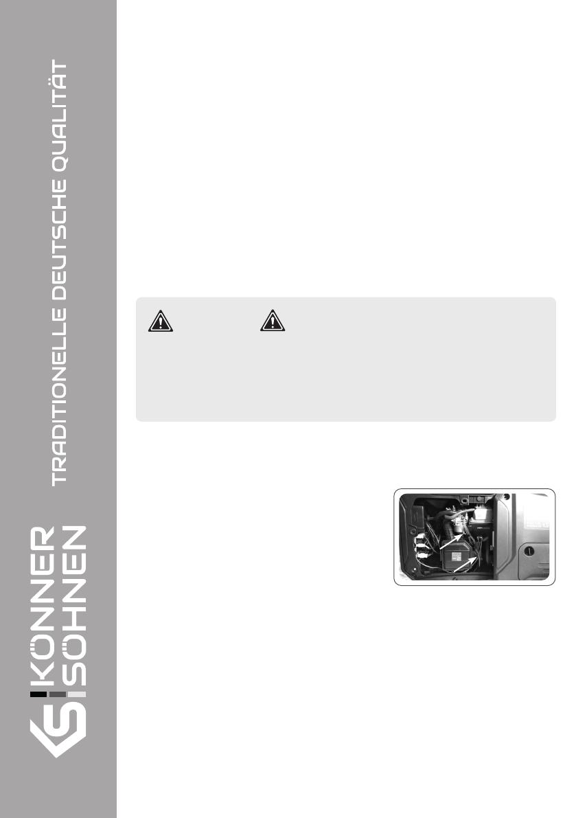
For all modifications of models KS 2000i, loosen the 4
screws on the side panel. Loosen drain screw C on the
carburetor and let the remaining fuel drain through pipe
D into the dedicated drip pan. Avoid petrol leaks. Tighten
up the screw. Install back the generator housing cover.
Start the generator on LPG.
To drain petrol from the carburetor, turn off the fuel valve and wait until the generator has cooled down
sufficiently. For open frame models, place a drip pan under the carburetor and loosen the drain screw on
the carburetor (Fig. 7). Make sure that no fuel leaks onto the generator. Tighten up the screw again. Start
the generator on LPG according to the instructions mentioned above
Disconnect the load from the generator before changing
fuel. The ECONOMY MODE switch must be in the “OFF”
position.
IMPORTANT!
For model KS 2000iG S: It is recommended to stop the generator before switching from petrol
to LPG! Petrol remains in the carburetor make it difficult to start the engine on LPG. Let the
generator run out of petrol until it stops. To do this, close the fuel valve with the generator
running and wait until the generator stops completely. Then start the generator on LPG.
You can also drain the remaining petrol from the carburetor before starting the generator
on LPG.
Fig. 7
С
KS 2000iG S
D
If during usage of petrol, need to switch to LPG supply, directly connect the LPG pipe,
turn on the LPG supply, and press the LPG RESET on the control panel to switch to LPG.
Fuel can be changed without stopping the generator. When switching from petrol to LPG operation, the
generator may be unstable during the rst 2-3 minutes and the low voltage protection may trip. If the red
indicator (overload indicator) lights up in 2-3 minutes after running the generator on LPG when it is running
stable, press the AC Reset BUTTON on a panel of generator to restore voltage supply
3. Connect the LPG hose to the LPG input (connect hose end A to the LPG input, as shown in Fig. 6).
4. Connect the hose end with the reducer to the gas cylinder (connect hose end B to the gas cylinder, as
shown in Fig. 6).
5. Open the gas valve on the cylinder, making sure that no gas is leaking.
6. Press the pressure relief valve on the reducer 2-3 times (only for model KS 2000i S).
7. Turn the Multifunctional engine switch to the “START” position.
8. For manual start, pull the manual starter until a slight resistance is felt, then pull it toward you relatively
sharply. Slowly turn the manual starter by hand, do not release it abruptly. For electric start, press the red
button on the multifunctional engine switch (fig. 3)
9. After starting the engine, turn the Multifunctional engine switch to the “RUN” position (fig. 3).
10. When using for the rst time, ll the gas line with gas by turning the key (pressing start button) to the
“OFF” position and slowly pull the starter handle to the full cord length 2 to 3 times (except for models
KS 8100, which do not have a manual start).
For model KS 2000iG S: Close the air choke (pull the air choke handle) if the generator is not warmed
up. Set the PETROL FUEL SWITCH to the “OFF” position, set the engine start to the “ON” position, grasp the
starter handle and slowly pull it until resistance is felt. Pull the starter cord to the full length with a sharp
movement. The generator will start. If this is not the case, repeat this action. Slowly turn the manual starter
by hand, do not release it abruptly. Open the air choke by pushing the air choke handle.
uk.koenner-soehnen.com | 18
ECON FUNCTIONECON FUNCTION
1. Start the engine.
2. Set the ECON switch to “ON”.
3. Plug the device into an AC outlet.
FUNCTIONAL DESCRIPTION
OF INVERTER GENERATORS 9
For models with electric start, check if the battery is charged. If necessary, recharge the battery with a
dedicated charger for lithium-ion batteries or start the generator with a manual start and allow it to run
idle while it is recharging.
CONNECTION OF GENERATOR WITH BUILT-IN ATS 8
Connection diagrams for generators with built-in ATS can be found in the full electronic version of the Connection diagrams for generators with built-in ATS can be found in the full electronic version of the
manual.manual.
Risk of electric shock! Network connection should only be
carried out by a qualied technician.
ATTENTION - DANGER!
It is forbidden to start the generator with the ECONOMY MODE ON. Economy mode
should be turned on only after starting the generator and only with a low load. Failure
to comply with this requirement may result in generator failure and void warranty
repair.
The ECON switch must be set to “OFF” to increase engine
speed to nominal. When connecting multiple power
consumers to the generator, be sure to first connect the
one with the highest starting current, and the device
with the lowest starting current should be connected
last.
IMPORTANT!
“ON” MODE“ON” MODE
When the ECON switch is in the “ON” position, the control unit monitors the engine speed, reducing it
commensurate with the connected load. If the engine speed is not enough to generate electricity to provide
the load, the control unit will automatically increase the engine speed.
As a result, fuel consumption is optimized and noise levels are reduced.
“OFF” MODE“OFF” MODE
The ECON switch must be set back to “OFF” when using electrical devices requiring a high starting current,
such as a compressor or submersible pump.
The ECON switch must be set back to “OFF” when using
electrical devices requiring a high starting current, such
as a compressor or submersible pump.
IMPORTANT!
This material is for informational purposes only and does not constitute a manual for
installing the equipment or connecting it to the mains, but we strongly recommend
that you read the instructions below. Equipment connection must always be carried out
by a certied electrician responsible for the installation and electrical connection of the
equipment according to local laws and regulations. The manufacturer assumes no lia-
bility for improper connection of the equipment or for any material or physical damage
that may result from improper installation, connection or operation of the equipment.
If during usage of LPG, need to switch to petrol, you only need to disconnect the LPG
supply, generator will automatically switch to petrol оperation, without other opera-
tions.
4. Make sure the AC indicator light is on.
5. Turn on the electrical device.
uk.koenner-soehnen.com | 19
  • Page 1 1
  • Page 2 2
  • Page 3 3
  • Page 4 4
  • Page 5 5
  • Page 6 6
  • Page 7 7
  • Page 8 8
  • Page 9 9
  • Page 10 10
  • Page 11 11
  • Page 12 12
  • Page 13 13
  • Page 14 14
  • Page 15 15
  • Page 16 16
  • Page 17 17
  • Page 18 18
  • Page 19 19
  • Page 20 20
  • Page 21 21
  • Page 22 22
  • Page 23 23
  • Page 24 24
  • Page 25 25
  • Page 26 26
  • Page 27 27
  • Page 28 28

KONNER SOHNEN KS 3300i Owner's manual

Category
Power generators
Type
Owner's manual

Ask a question and I''ll find the answer in the document

Finding information in a document is now easier with AI