Page is loading ...

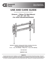
(Fits all TVs up to 90" with max weight of 150 lbs)
Tilting Wall Mount for Flat Panel TVs
Questions, problems, missing parts? Before returning to the store,
call Paragon Group USA Customer Service
9 a.m. - 5 p.m., Monday to Friday
Toll Free 1.888.783.6082
www.link2home.com
Model: MB-19052

This mount has been tested to
support televisions of all sizes
with maximum weight as follows:
5/8 in and 1/2 in DRYWALL:
95 lbs. (43kgs)
CONCRETE WALLS:
150 lbs. (68kgs)
Before you begin, carefully read and understand the instructions
in this manual. Please follow the instructions in the order
presented in this manual and observe all warnings and cautions.
for use only with the maximum weights
indicated. Use with products heavier than
the maximum weights indicated may result
in collapse of the mount and its accessories
causing possible injury. This mount has been
tested to support up to 150 lbs (68kg) on
Concrete Wall and 95 lbs (43kg) on 5/8 in.
and 1/2 in. Drywall.
This wall mount is intended
min2.95"-max3.34"
(min75mm-85mm)
min3.93"-max23.62"
(min100mm-max600mm)
2.87"(73mm)
min3.93"-max15.74"
(min100mm-max400mm)

Pre-Installation
AA
Nylon anchor
4
4
4
4 each
4 each
8 each
AA
BB
CC
DD
EE
FF
Lag washer
Lag bolt
Screw (size M4x14,M5x14,M6x14,M4x30,M5x30,M6x30,M8x30,M8x50)
Washer (size D5 and D8)
Spacer (size Φ15xΦ8x5 and Φ15xΦ8x15)
4
GG
Drywall anchor (For use only with 5/8 in and 1/2 in Drywall)
DD
CC
BB
EE
FF
GG
A
C D F
B
E
Wall plate 2
2
4
4
A
TV bracketB
Bracket extensionC
D Screw
1
E Mounting template
1
F Level
SPACE SAVER
Mounting Systems
VESA Standard Ruler
500
500
600
600
400
400
300
300
200
200
100
100
NOTE: The hardware included is suitable
for mounting to walls made of solid concrete
using (AA BB and CC) and unique (GG) anchors
for mounting on plasterboard walls. If your
mounting situation is different, please consult
a qualified installer or contact customer service
at: 1.888.783.6082
Toll Free 1.888.783.6082

Screw is too
long
Screw is too
short
Screw ts
correctly
To ensure proper mounting of the brackets to your
TV, this mounting system includes several sizes
(M4, M5, M6, and M8) of screws (DD).
Select the screw diameter to use by inserting
the various sized screws (M4, M5, M6, and M8)
into the mounting holes in the back of your TV
to identify the right size.
10 20 30 40 50 60 70 80 90 100mm
1 2 3 4in
injuries and property damage, make sure that
there are adequate threads to secure the
brackets to your TV. If you encounter resistance,
stop immediately and contact customer service.
Use the shortest screw and spacer combination
to accommodate your TV. Using hardware that is
too long may damage your TV. However, using
a screw that is too short may cause your TV to
fall from the mount.
To avoid potential personal
CAUTION:

Left insert
Right insert
Left insert
Right insert
OR
3
Attaching the mounting brackets
to the TV
Before attaching the mounting brackets to the TV, measure the distance from the left insert to
the right insert on the back of your TV using the included VESA standard ruler or a Tape Measure.
You will need this information when you install the wall mount pieces on the wall.
Attach the bubble level (F) into the mounting template (E).
Installation (continued)
Toll Free 1.888.783.6082
E
F
SPACE SAVER
Mounting Systems
VESA Standard Ruler
500
500
600
600
400
400
300
300
200
200
100
100
SPACE SAVER
Mounting Systems
VESA Standard Ruler
100
4
If the VESA on your TV is 100 or 200 up to bottom you will not need to use the bracket extensions (C).
Assemble the mounting brackets
TVs 200 VESA

Installation (continued)
CAUTION: Tighten the screws so the brackets
are firmly attached. DO NOT OVERTIGHTEN. This
may damage your TV.
If The VESA is 300 or 400 up to bottom you need to add the bracket extensions (C) as shown in the
drawing below.
Attach the bracket extensions (C) to TV bracket with screws.
D
C
B
C
FF
EE
DD
TVs 200 VESA
TVs >200 VESA
Use of the spacers (FF) will
vary depending on the type of
TV you will be mounting.
DD
EE
FF
TVs >200 VESA

For Plasterboard/ Sheetrock walls mount directly on the board, no stud is required.
PLANNING WALL PLACEMENT
5
Installation (continued)
Toll Free 1.888.783.6082

8
Installation (continued)
E
AA
A
BB
CC
21
3 4
6
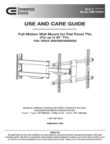
Use the mounting template (E) to mark the installation holes. Use a level to ensure the plates are level.
Use 1/4 in. (6 mm) drill bit to drill a pilot holes and then use a 3/8 in (10 mm) masonry drill bit to slowly drill
2.4 in (60 mm) holes.
Use Nylon anchors (AA), lag bolts (CC), and washers (BB) to mount the wall plates (A) to the wall.
When mounting distance is larger than 600 mm, Use a tape measure and a level first to mark the mounting position.
(10 mm) 3/8 in(6 mm) 1/4 in
(60 mm) 2.4 in
Installing the wall plates (concrete wall)

9
Installation (continued)
Toll Free 1.888.783.6082
7
Installing the wall plate (drywall/sheetrock/plaster wall)
Use the mounting template (E) to mark the installation holes. Use a level to ensure the Plates are leveled.
Use a 3/8 in. (10 mm) drill bit to slowly drill pilot holes.
You may have a situation when you can use one wood stud (most likely you will not be able to use the 2 wood studs
due to unmatched distance).
In this case you can Use 5/32 in (4mm) drill bit to drill a pilot holes on the wood stud and screw the wall plate with
(CC) Lag bolt directly on the wood stud.
Remove the screws from the 4 Drywall Anchors (GG). Insert the BODY ONLY of the Drywall Anchors (GG) into
the four pilot holes previously drilled.
Re-insert the screws into the Drywall Anchors (GG) – do not overtighten the screws, you will be removing them.
This will cause the Drywall Anchors (GG) to expand inside the drywall/sheetrock/plaster.
Once again, remove the screws from the Drywall Anchors (GG) that you have installed in the surface.
Align each Wall Plate (A) over the corresponding two mounting holes. Insert the Drywall Anchor (GG) screws that
you previously removed and screw them into each hole of the Wall Plate (A). You can now screw them fully down
being careful to not overtighten.
Your Wall Plates (A) are now installed.
E
GG
1 2
A
3 4
5 6

10
Installation (continued)
Mounting the TV to the wall Plates
Hang the TV
HEAVY! You will need
assistance with this step.
8
9
Adjusting the TV to the desired position
To tilt the TV, gently lift the TV with both hands, one on the top and one on the bottom. To tilt
larger televisions, use two people.

11
Installation (continued)
Toll Free 1.888.783.6082
HEAVY! You will need
assistance with this step.
Removing the TV from the wall
To remove the TV from the wall, gently grasp the TV on both sides. Gently lift the TV directly up,
it will stop moving up at approximately 1/2 in, at this point gently pull the TV toward you and
continue lifting up. The TV will slide out of the mount and you can remove it from the wall. As
always it is recommended you have help whenever moving or mounting your TV from the wall.
10

Questions, problems, missing parts? Before returning to the store,
Call Paragon Group USA Customer Service
9 a.m. - 5 p.m., Monday to Friday
Toll Free 1.888.783.6082
/