Page is loading ...

FULL DC INVERTER SYSTEMS
USER’S MANUAL
CCM03, CCM10
COMMERCIAL AIR C O N D IT I O N E R S SDV4

Please keep this specifications manual properly.
Read this specifications manual carefully before using the equipment.
Original instructions

1
CONTENT PAGE
I.Installation part
Packing list and precautions.............................................1
Notes to installation...........................................................1
Installation procedure........................................................2
Wiring procedure...............................................................2
Safety precautions............................................................2
System wiring instruction..................................................2
II. Operation part
Basic conditions of operating the electric controller..........2
Function categories of electric controller..........................2
Functions of components..................................................2
System composition.......................................................3
Keywords and general function description...................3
Schematic diagram of centralized controller keys..........3
Electric control function description
(keypad operation instruction)........................................3
General display data entries........................................4
LCD display description...............................................5
Fault and protection code table....................................5
Technical indices and requirements...............................6
Chart.1............................................................................8
Chart.2............................................................................9
Chart.3..........................................................................10
Chart.4..........................................................................11
Chart5 (LCD full display diagram)................................12
Chart.6,7,8,9.................................................................13
I&O manual
Thank you for your confidence in SINCLAIR.
SINCLAIR 2nd-Generation Centralized Controller
This specification manual describes the conditions of
operating the centralized controller and its control functions.
This specification manual is applicable to centralized
controllers. But the functions available from the centralized
controller described herein or the displayed data need support
of the main control board of the air conditioner.
For convenience of future reference, keep this manual
properly after reading it.
For any question, contact the distributor.
Applicable model: CCM03, CCM10
2. Installation assemblies prepared on the site
Serial
No
.
Name
Quant
ity
(I
nstall into
wall)
Selecte
d
model
Remarks
1 3-core control
shielded
cable
2 PCS
RVVP-
300/300
3x0.75mm
2
One for
communicating
with network
interface
module;
the other for
communicating
with the computer.
2 3-core cable 1 PCS
RVV-300/500
3x1.5mm
2
For power supply
of
monitor
3 Switch box 1 PCS -------- --------
4 Wire pipe (jack
casing
pipe,
capti
ve nut)
2 /3 PCS -------- --------
5 Tighten strip Several
pieces
--------
For binding cables(as
the case may be)
Serial
No
.
Nam
e Quantity Remarks
1 2
nd
-generation indoor
unit
centralized
controlle
r
1 PCS CCM03/E, CCM10/E
2 Fastening cross
groo
ve pan head
self-tapping
screw
6 PCS GB845/ST3.8X25-C-H
(S)
3 Fastening plastic
expansion pipe
6 PCS 6X30
4 Installation &
Operation
Manual
1 PCS SDV06IU-012a
5 Matching resistance 2 PCS 120 ohms
1. Packing box list of 2nd-generation indoor unit centralized
controller
CCM03,CCM10. Check whether the assemblies are
complete
.
List of fittings and precautions
Notes to installation
Correct connect ion
Correct connect ion
Incorrect connection
Incorrect connection
Notes to installation of centralized controller:
1. Power supply of the centralized controller. Connect the
220V~50Hz power supply to the L and N sides of the terminal on
the back of the centralized controller
.
2.
Do not place the signal cable and power cable of the central-
ized controller into the same wire pipe. An interval of
300~500m
m should exist between the two pipes.
3.
The main signal cable of the centralized controller shall
not exceed 1200m.
4.
No intermediate joint is allowed for the shielded cable. If joints
ar
e inevitable, crimp it with the terminal.
5.
After the centralized controller is connected, do not use
megohmmeter to inspect insulation of the signal cable.
6. Wiring mode of the centralized controller and the network
interface:
The communication port between the centralized controller and
the
network interface of the air conditioner is polarity-sensitive. The
X,
Y and E at both sides should correspond properly. Dot not
cross-connect
cables. The same principles apply to the RS485-
RS232 of the centralized controller.
I. Installation part
φ

2
I&O manual
Installation procedure
I. Procedure of installing electrician switch box of centralized
controller
The size of the centralized controller wire depends on the length.
Use a wiring pipe adaptable to the wires of the centralized
controller to perform installation. Insert the flathead screwdriver
into the concave on the upper side of the box, and rotate slightly
to open the upper cover of the centralized controller.
Wiring procedure
NOTE
Network air conditioner wiring diagram (two types for indoor unit:
(1) The main control board needs an external network interface
module;
(2) Network interface module is built in the main control board).
Safety precautions
! Read the safety precautions carefully before installing the unit.
! Stated below are important safety issues that must be obeyed.
! The meanings of all parts are as follows:
! Upon completion of the installation, check whether the trial run
is normal, and deliver the user's manual to the user.
The RS485-to-RS232 module in the wiring diagram and
the wires are put into use only when the network
system needs to be connected with the computer. One
computer can be connected with 16 centralized
monitors as a maximum. Namely, a maximum of
16X64=1024 indoor units can be connected. The
centralized controllers are differentiated by address bits.
The configurable range is 0~15. No duplicate
address of centralized controller is allowed in a unified
network.
Warning
Means improper handling may lead to
personal injury or property loss.
Note
Means improper handling may lead to
personal death or severe injury.
Warning
Please entrust the distributor or professionals to install the
equipment. Installation by unauthorized persons may lead to
imperfect installation which may result in electric shock or fire.
Adhere to this installation manual. Improper installation may lead
to electric shock or fire.
Reinstallation must be performed by professionals. Improper
installation may lead to electric shock or fire.
Do not uninstall the eq on. Unauthorized
uninstalling may lead to ating or fire of the
air conditioner.
uipment without permissi
abnormal operation, he
Note
Do not install the equipment in a place vulnerable to leakage of
flammable gases. Once flammable gases are leaked and left
around the centralized monitor, fire may occur.
The wiring shall adapt to the current of the centralized monitor.
Otherwise, electric leakage or heating may occur and result in
fire.
(see in Chart.1)
(see in Chart.2)
System wiring instruction
1. Wiring diagram of building network air conditioning system.
Wiring diagram with good
communication effect
Wiring diagram with poor
communication effect (not
recommended because it may lead
to poor communication)
2. System wiring diagram of centralized monitoring and indoor unit
of air conditioner
Both of the following wiring modes of centralized monitor and
indoor unit are applicable: (Quantity of indoor units connected with
each centralized monitor is less than or equal to 64).
Indoor unit
Indoor unit Indoor unit
Indoor unit Indoor unit Indoor unit
Indoor unit
Indoor unit
Indoor unit Indoor unit
Indoor unit Indoor unit
Centralized controller
Centralized controller
II. Operation part
(1) Applicable range of supply voltage:
Input voltage: Single-phase 198V ~ 242V;
AC input power supply frequency: 50Hz/60Hz compatible.
(2) Operating environment temperature of electric controller:
-15°C~+43°C.
Operating environment RH of electric controller:
RH40%~RH90%.
Functions of the electric controller:
(1) System composition
(2) Keywords and general function description
(3) Description of electric control functions of centralized controller
(4) Technical indices and requirements
Basic conditions of operating the electric
controller
Function categories of electric controller
Function description of each part

System composition
The centralized controller is used to perform centralized
control and data query for the network air conditioner. Each
centralized controller can communicate with a maximum
of 64 air conditioners to make up an air conditioner LAN,
and implement centralized monitoring for the air conditioners in
the network.
The centralized controller can be interfaced with computer
or gateway to implement centralized control and status query
for all air conditioners in the network. It can be connected with
WAN via computer or gateway to implement remote
computerized control (with support of computer software).
Each local computer or gateway can be connected to 16
centralized controllers as a maximum.
The master/slave answer mode is implemented for
communication between the centralized controller and the
air conditioner, between the computer and the centralized
controller. In the LAN composed of centralized controller and air
conditioner, the centralized controller is a master, and the air
conditioner is a slave. In the LAN composed of computer
and centralized controller, the computer or gateway is a
master, and the centralized controller is a slave.
3
I&O manual
1
2
3
Keywords and general function description
Power on or reset
When the centralized controller is powered on or reset, all
display segments of the LCD are luminous for 2 seconds
and then goes off. 1 second later, the system enters the
normal display status. The centralized controller is in the
main page display status and displays the first page,
and searches the in-service air conditioners in the
network. Once the search is finished, the centralized
controller enters the mode setting page, and sets the first
in-service air conditioner by default.
Network area address of centralized controller
The local computer or gateway can be connected with
16 centralized controllers for communication. Each
centralized controller serves as an area of the air
conditioner network. The centralized controllers are
differentiated by bit selection address. The configurable
range is 0~15.
State indication
If any local keypad operation is setting the operation status of
the air conditioner, the indicator is on when the signals are
sent. Upon completion of the setting process, the indicator
goes off. If an in-service air conditioner in the network
is faulty, or the centralized controller network itself is faulty,
the indicator will blink at 2Hz.
If one or more in-service air conditioners in the network
are running, including under setting of timing
start/shutdown, the indicator will be luminous. Otherwise, the
indicator is off.
Locking of centralized controller
After receiving the centralized controller locking command
sent from the computer, the centralized controller
disables the startup/shutdown and setting of the air
conditioner, and sends commands to lock remote controllers
of all air conditioners in the network of the centralized
controller. After receiving the unlocking command, the
centralized controller enables the startup/shutdown
operation, and sends commands to unlock the remote
controller of all air conditioners.
1
2
3
Schematic diagram of network control system composi-
tion of air conditioner:
(see in Chart.3)
The locking status of the remote controller can be locked
or unlocked by the computer or centralized controller
separately. The locking status of the centralized controller is
memorized after power failure of the centralized controller, and
will not vanish after the power supply is restored, unless the
command of unlocking is received.
Mode locking function
After the mode locking command is received, the command
is forwarded to the air conditioner, and the centralized
controller displays the mode locking flag. After the command of
unlocking is received, the non-conflict mode can be
selected freely. The centralized controller can also lock
modes of all indoor units.
Emergent shutdown and compulsory startup
When the emergent shutdown switch of the centralized
controller is turned on, all air conditioners in the network of the
centralized controller will shut down compulsorily. The
centralized controller and computer and all functional
modules are disabled from startup and shutdown until the
foregoing switch is turned off. When the compulsory startup
switch of the centralized controller is turned on, all air
conditioners in the network of the centralized controller will
start up compulsorily. By default, they will run in the cooling
mode. The startup and shutdown operations of the
centralized controller and the computer and all functional
modules will be disabled (only the command of startup is
sent to the air conditioner, without affecting operation of the
remote controller after startup) until the foregoing switch is
turned off.
If the foregoing two switches are turned on concurrently,
the emergent shutdown switch shall have preference.
4
5
6
1) Query key
Any time when you press the key, the selected operation mode
is to query the operation status of the air conditioner. By default,
the first in-service air conditioner will be queried. Through the
Increase and Decrease keys, you can change the parameter
page to be queried; through the Up, Down, Left and Right keys,
you can change to query status of other in-service air
conditioners.
2) Set key
In other display mode, press the key to enter the setting mode.
By default, it is single setting, and the first in-service air
conditioner is displayed. In setting operation mode, press the
key again, and the operation will be performed for all air
conditioners in the network. Press the key repeatedly to shift
between single setting and global setting.
→ Single → Global →
Electric controller function description
---Keypad operation description
(see in Chart.4)
3) Mode key
In setting operation mode, press this key to set the operation
→cooling → heating → supply air only → stop →
In other display mode, press the key to enter the setting mode.
By default, it is single-machine setting, and the first in-service air
conditioner is displayed.

4
I&O manual
4) Fan key
In
setting operation mode, press this key to set the fan of the
indoor
unit of the air conditioner to run in the automatic, high,
medium or lo
w level of air.
→ auto → low → medium → high →
5)
Time on key
In
setting operation mode, press this key to set the timing startup
of
air conditioner; press the key again to exit the timing setting,
and
restore the normal temperature regulation operation mode.
→ time on → set temperature regulation →
6) Time off key
In
setting operation mode, press this key to set the timing
shutd
own of air conditioner; press the key again to exit the timing
setting,
and restore the normal temperature regulation operation
mode.
→ time on → set tempe
rature regulation →
7)
Swing key
In setting operation mode, press this key to enable or disable the
swing function. If all currently selected air conditioners have no
swing function, no effect will result after pressing the key.
8)
Leftward key
In
the query mode, every time when you press the key, the
operation
status data of the previous air conditioner will be
displa
yed.
If
it is currently on the first machine, press the key again, and the
data
of the last machine will be displayed. If you hold down this
ke
y, the address will decrease one by one.
In
the setting mode, every time when you press the key, if it is in
single
operation mode, the air conditioner of the previous
in-service
address number will be selected. If it is in the global
operation mode, no effect
will result after the key is pressed.
In
the main page, press the key to enter the query mode. By
default, it is the first in-service air conditioner.
9)
Rightward key
In
the query mode, every time when you press the key, the
operation
status data of the last air conditioner will be displayed.
If
it is currently on the last machine, press the key, and the data
of
the first machine will be displayed. If you hold down this key,
the address
will increase one by one.
In
the setting mode, every time when you press the key, if it is in
the
single operation mode, the air conditioner of the next
in-service address number
will be selected.
If
it is in the global operation mode, no effect will result after the
ke
y is pressed. In the main page, press the key to enter the
quer
y mode. By default, it is the first in-service air conditioner.
10)
Downward key
In
the query mode, every time when you press the key, the
operation
status data of the air conditioner corresponding to the
next
row of the matrix will be displayed. If it is currently in the last
row, press the key, and the data of the air conditioner
corresponding
to the first row will be displayed. If you hold down
this ke
y, the row will increase one by one.
In
the setting mode, every time when you press the key, if it is in
the
single operation mode, the air conditioner corresponding to
the
last row will be selected. If it is in the global operation mode,
no effect
will result after the key is pressed.
In
the main page, press the key to enter the query mode. By
default, it is the first in-service air conditioner.
11)
Upward key
In
the query mode, every time when you press the key, the
operation
status data of the air conditioner corresponding to the
previous
row of the matrix will be displayed. If it is currently in the
first
row, press the key, and the data of the air conditioner
corresponding
to the last row will be displayed. If you hold down
this ke
y, the row will decrease one by one.
In
the setting mode, every time when you press the key, if it is in
the
single operation mode, the air conditioner corresponding to
the
previous row will be selected. If it is in the global operation
mode, no effect
will result after the key is pressed.
In
the main page, press the key to enter the query mode. By
default, it is the first in-service air conditioner.
12) Add key
In
the main page or the query mode, every time when you press
the
key, the data of the last page will be displayed. If it is now in
the
last page, press the key again, and the first page will be
displa
yed.
In
the setting mode, every time when you press the key, if it is in
the
temperature regulation mode, the set temperature will
decrease b
y 1 °C until the highest allowed set temperature;
if
it is in the timing startup/shutdown time setting mode, select
the
upper-level set time, if no time is set, 0.0 will be displayed, if
you
hold down the key, the upper-level data will be selected
consecutivel
y.
The specific change mode is as follo
ws:
0.0→0.5→1.0→1.5→2.0→2.5→3.0→3.5→4.0→4.5→5.0→5.5→6.0→6.5→7.0
→7.5→ 8.0→8.5→9.0→9.5→10→
11→12→13→14→15→16→17→18→19
→20→21→22→23→24
13) Reduce key
In
the main page or the query mode, every time when you press
a key, the data of the current page will be displayed. If it is now in
the
first page, press the key again, and the last page will be
displa
yed.
In
the setting mode, every time when you press the key, if it is in
the
temperature regulation mode, the set temperature will
decrease b
y 1 degree until the lowest allowed set temperature;
if
it is in the timing startup/shutdown time setting mode, select
the
upper-level set time, if no time is set, 0.0 will be displayed, if
you
hold down the key, the upper-level data will be selected
consecutivel
y.
The specific change mode is as follo
ws:
0.0← .5←1.0←1.5←2.0←2.5←3.0←3.5←4.0←4.5←5.0←5.5←6.0←6.5←
7.0←7.5←8.0←8.
5 ←9.0←9.5←10←11←12←13←14←15←16←17←
18←19←20←21
←22←23←24

5
I&O manual
14) ON/OFF key
Any time when you press the key, the centralized
startup/shutdown operation is performed for all current in-service
air conditioners in the centralized controller network. If all
in-service air conditioners in the network are in the power-off
status, press the key to perform the startup operation. If it is in
the mode setting page currently, and the parameters such as
startup mode, temperature and air speed are selected, the air
conditioner will be started according to the selected parameters.
If no mode is selected currently, and the air conditioner is
powered off or it is in other display page currently, and the
default startup mode is: Cooling, strong air, set temperature
24°C, swing function enabled. The default startup mode is
locked according to the system mode or judged according to
other constraint conditions. If any conflict exists, the next
conflict-free mode will apply automatically. If conflict exists for all
modes, startup will be impossible. If one or more in-service air
conditioners in the network (including in the timing process of
timing startup/shutdown), pressing this key will shut down all air
conditioners. When performing the shutdown operation, the
shutdown command is issued to the air conditioners in the startup
status only, and is not issued to those in the shutdown status.
15) Lock key
In the mode setting mode, press the Lock key, and the remote
controller of the currently selected air conditioner will be
locked/unlocked. The operation mode is: If you select
single-machine setting, the operation is performed for the air
conditioner of the current address only. If the remote controller of
the air conditioner is locked currently, issue the lock command;
otherwise, send the lock command. If you does not select the
single-machine mode, and the remote controller of one or more
currently selected air conditioners is locked, issue the unlock
command; if the remote controllers of all currently selected air
conditioners are in the non-locked status, issue the remote
controller lock command.
When the remote controller of the air conditioner is locked, the
air conditioner does not receive remote control signals from the
remote controller or wire controller until the remote controller is
unlocked. Press the Query key and then press the Lock key,
and
the keys of the centralized controller will be locked or unlocked.
If the keys are currently locked, press the foregoing keys
concurrently again, and the keys will be unlocked; if the keys are
currently unlocked, press the foregoing keys concurrently, and
the keys will be locked. If the keys are locked, pressing of any
key other than the Unlock key will be ineffective.
In the unified setting page, press the Up key and the Lock key
concurrently to lock all air conditioner modules in the network.
The mode locking is cancelled when the key is pressed again.
Note: When you lock or cancel locking, the corresponding icon
indication appears or disappears only after all the
attached air conditioners are set completely, so it takes a
time period. When the number of attached air
conditioners is high, wait patiently.
16) Confirmation key
In the setting mode, press the key to send the currently selected
mode status and the auxiliary function status to the selected air
conditioner, and display the mode setting operation results.
After you select the operation mode and auxiliary function status
information of the air conditioner, if you do not press the
confirmation key, the selected information will not be sent to the
air conditioner, and will not affect the current operation of the air
conditioner.
The operations of remote controller locking and unlocking need
no pressing of the confirmation key. The command information is
sent directly after the locking key is pressed.
17) Reset key
Anytime when the reset key is pressed, the centralized controller
will reset. The result is the same as the result of restoring
power-on after power failure.
General display data entries
1) General display data is displayed in all display pages.
a. Under the interconnected control of the computer or
gateway, the data is displayed in graphic. Otherwise, no
data is displayed.
b. If the centralized controller is connected with the functional
module for communication, the data is displayed in graphics.
Otherwise, no data is displayed.
c. If the centralized controller is connected with the SMS
remote control module for communication, the data is
displayed in graphics. Otherwise, no data is displayed.
d. If the centralized controller is connected with the telephone
remote control module for communication, the data is
displayed in graphics. Otherwise, no data is displayed.
e. In normal operation of the centralized controller, the
periodical cycle module communicates with the network
interface module, and the data is displayed dynamically and
cyclically (blank).
f. In the centralized control locked status or the keypad locked
status, the locking flag is displayed. After unlocking, it is not
displayed. In the centralized controller locked status, the
flag blinks at 0.5Hz; in the keypad locked status, the flag is
displayed constantly. If both of them are locked concurrently,
the flag is displayed constantly.
g. In the setting page, if the selected air conditioner is in the
remote controller locked status (in case of non-single
machine operation, as long as one machine is in the remote
controller locked status, it is deemed the locked status), the
flag is displayed constantly.
h. If all indoor units lock the cooling mode, this flag will display;
if all indoor units lock the heating mode, this flag will display.
2) Data display handling
1. Indoor unit code (address) display: Display range: 00~63;
with “#” being luminous concurrently.
2. Indoor temperature display: Display range: 00~99°C. “°C”
and “indoor temperature” are displayed concurrently. If the
temperature is higher than 99°C, “_99°C” is displayed. If the
temperature value is invalid, “—” is displayed.
3. If timing startup/shutdown is set, the flag is displayed.
4. T3, T2A and T2B display: In the single-machine query page,
display can shift between “T3”, “T2A” and “T2B”, and the
temperature value is displayed concurrently, with the
corresponding “°C” being luminous.
5. In case of air conditioner fault or protection, the
corresponding fault code or protection code can be displayed.

6
I&O manual
6. Liquid crystal matrix display description:
1. The liquid crystal matrix is composed of 4*64 grids, and each
grid is composed of two blocks of different sizes (as shown in the
above figure).
2. The matrix includes horizontal coordinates 00-15 on the upper
side and vertical coordinates 00+, 16+, 32+ and 48+ on the left
side, which indicate the address of the indoor unit. The sum of
the horizontal coordinate and the vertical coordinate of the grid is
the address of the grid. Each grid corresponds to an indoor unit
of this address.
3. One grid is composed of two blocks of different sizes. The status
indication table is as follows:
Status
Object
Constantly on
Slow
blink
Fast
blink
Big black
block
In-service Selected
Out of
service
Small
black
block
Power on
Fault of
indoor
unit
Power
off
(see in Chart.5)
LCD display description
1. Description of the standby page
1) The LCD displays the standby page, 60 air conditioners are
in service, of which 28 are powered on and 32 off.
2) In the matrix, the big dots of (00, 16+) and (15,32+) are
luminous, and the small dots are not luminous. It indicates
the 32 air conditioners with the addresses from 16 to 47 are
powered off.
3) In the matrix, the big and small dots of (09, 48+) and (12,
48+) are not luminous. It indicates the four air conditioners
with the addresses from 57 to 60 are outside the network.
4) All other big and small dots in the matrix are luminous. It
indicates all other air conditioners are in the network and
powered on.
5) The address of the air conditioner is sum of the coordinates.
For example, the address of (09, 48+) is 09+48=57.
6) The centralized controller keypad is locked, and the
centralized controller communicates with the computer
normally.
(see in Chart.6)
2. Description of the query page
1) The LCD displays the query page, and the air conditioner with
the address of 08 is being queried. Mode of the air conditioner
with the address 01 is: Cooling, strong air, swing on, indoor
temperature 22°C, set temperature 20°C, cooling mode “lock”.
2) In the matrix, only the big and small black dots at (00, 00+) and
(01,00+) are luminous. It indicates the in-service and power-on
status of the air conditioners with the addresses of 00 and 01.
3) The centralized controller communicates with the computer
normally.
(see in Chart.7)
3. Description of the setting page
1) The LCD displays the setting page, and queries the air
conditioner with the address of 08. The mode of the air
conditioner with the address 08 is: Cooling, strong air, swing on,
indoor temperature 28°C, set temperature 22°C, cooling.
2) In the matrix, only the big black dots from (08, 00+) to (16, 00+)
are luminous. It indicates the air conditioners with the addresses
from 08 to 16 are in service.
3) The centralized controller communicates with the computer
normally.
(see in Chart.8)
4. Fault page display description
1) Query the air conditioner with the address of 08 in the query
page. The air conditioner with the address of 08 is faulty, and the
fault code is 08. The big black dot below (08, 0+) blinks.
2) In the matrix, only the big and small black dots from (00, 00+) to
(16, 15+) illuminate. It indicates the in-service status of the air
conditioners with the addresses of 00 and 01.
3) The centralized controller communicates with the computer
normally.
(see in Chart.9)
Fault and protection code table
Fault code Fault content Description
EF Other faults
EE Water level detection faults
ED Outdoor unit fault protection
EC Cleaning fault
EB Inverter module protection
EA Over-current of compressor (4 times)
E9
Fault of communication between main
board and display board
E8 Air speed detection out of control
E7 EEPROM error
E6 Zero crossing detection error
E5
T3 or T4 or digital compressor discharge
temperature sensor fault
E4 T2B sensor fault
E3 T2A sensor fault
E2 T1 sensor fault
E1 Communication fault
E0 Phase order error or phase loss
07#
06#
05#
04#
03#
02#
01#
Fault of communication between
centralized controller and computer
(gateway)
00#
Fault of communication between
centralized controller and functional module
Fault of communication between
centralized controller and network interface
module
Fault of communication between network
interface module and main control board

7
I&O manual
Protection
code
Protection content Description
PF Other protection
PE Reserved
PD Reserved
PC Reserved
PB Reserved
PA Reserved
P9 Reserved
P8 Over-current of compressor
P7
Power supply over-voltage and
under-voltage protection
P6 Discharge low pressure protection
P5 Discharge high pressure protection
P4 Discharge pipe temperature protection
P3 Compressor temperature protection
P2 Condenser high-temperature protection
P1 Anti cool air or defrost protection
P0 Evaporator temperature protection
1. EMC and EMI comply with the CE certification requirements.
2. The electric safety complies with the requirements of
GB4706.32-2004 and GB/T7725-2004.
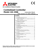
Technical indices and requirements

Installation screw
holes (4 holes)
Installation dimensions:
As shown in the figure
on the right side.
Rotate the flathead screwdriver slightly
to open the upper cover (at points).
Screws for fixing the centralized
controller ( )GB845/ST3.9*25
Upper
cover
Holder
Address
bits
Bit location
Address range
a
00 ~ 15
Power cable interface of centralized controller (198V~242V)/(50 / 60HZ
)
Communication interface with computer
Communication interface with indoor interface
Emergent
stop
switch
Emergent
start
switch
(Chart.1)
8
I&O manual

Matching resistance of communication end is 120 .
Centr alized contr oller
Centr alized controller
One centralized controller can be connected to 64
indoor units as a maximum
One centralized controller can be connected to
64 indoor units as a maximum
One centr alized controller can be connected to
64 indoor units as a maximum
One centralized controller can be connected to
64 indoor units as a maximum
RS232 Pin hole: for connection
to computer COM por t
RS485 Conver ted
RS232 module
9
I&O manual
(Chart.2)
POWER
POWER
POWER

10
I&O manual
air conditioner
Network interface
Local computer
,QWHUQHW
The network interface
may be integrated
into the indoor unit
or main control board.
Centralized controller
A maximum of 64 pieces
A maximum of 16 pieces
(Chart.3)

ot
ye
k ”kc
oL
“
eht s
serp ,egap gnittes eht nI .1
.rell
or
t
noc e
tomer eh
t kcol
nu ro kc
ol
y
e
k
”pU
“
e
ht
sse
rp
,
ega
p
gnittes deifinu eht nI .2
.
e
dom
e
ht
k
col
n
u ro
kco
l o
t
ye
k
”
kc
oL“ eht
s
se
r
p
eht
dn
a
yek ”kc
o
L“ e
h
t s
ser
p
,
ye
k ”y
r
e
uQ“
e
ht
gnis
s
erp
retfA .3
.r
el
lortnoc d
ezi
l
art
ne
c e
ht f
o
da
p
ye
k
e
ht kc
olnu
ro kco
l
o
t
mode of the air conditioner as cooling, heating, or air supply.
11
I&O manual
(Chart.4)

retupmoC
noitacinummoc
erutarepmet roodnI
ruoH
FFO/NO gnimiT
kram
erutarepmeT
retemarap
:noitceles edoM
,gnilooc ,otuA
gnitaeh gnittewed
deeps ylppus riA
eludom
noitcnuF
noitacinummoc
eludom SMS
noitacinummoc
eludom enohpeleT
noitacinummoc
dna tluaF
edoc noitcetorp
D
e
w
e
t
t
i
n
g
f
u
n
c
t
io
n
noitalitneV
E
le
c
t
r
i
c
a
u
x
il
ia
r
y
h
e
a
t
i
n
g
f
u
n
c
t
i
o
n
noitcnuf gniwS
C
o
m
m
u
n
i
c
a
t
i
o
n
s
t
a
t
u
s
noita
repo yalpsiD
,yreuQ :sutats
,gnipuorg ,gnittes
noitarepo
gnikcol yeK
R
e
m
o
t
e
c
o
n
t
r
o
l
le
r
l
o
c
k
i
n
g
H
e
a
t
in
g
m
o
d
e
o
c
k
i
n
g
C
o
o
li
n
g
m
o
d
e
l
o
c
k
i
n
g
edom gnitteS
F
llu
d
si
p
al
y
o
DCL f
(Chart.5)
(1.6)
12
I&O manual

(Chart.6)
(1.6)
(Chart.7)
(Chart.8)
(Chart.9)
13
I&O manual

NOTE CONCERNING PROTECTION OF ENVIRONMENT
This product must not be disposed of via normal household waste after its service life, but
must be taken to a collection station for the recycling of electrical and electronic devices. The
symbol on the product, the operating instructions or the packaging indicate such disposal
procedures. The materials are recyclable in accordance with their respective symbols. By
means of re-use, material recycling or any other form of recycling old appliances you are
making an important contribution to the protection of our environment. Please ask your local council where
your nearest disposal station is located.
INFORMATION CONCERNING USED REFRIGERANT MEDIUM
This unit is containing fluorinated gases included in the Kyoto protocol. The maintanance and the liquidation
must be carried out by qualified personel.
Type of refrigerant: R410A
The composition of the cooling medium R410A: (50% HFC-32, 50% HFC-125)
The quantity of the refrigerant: please see the unit label.
The value GWP: 2088
GWP = Global Warming Potential
In case of quality problem or other please contact your local supplier or authorized service center.
Emergency number: 112
PRODUCER
Producer: SINCLAIR CORPORATION Ltd., 1-4 Argyll St., London W1F 7LD, UK, www.sinclair-eu.com
This product was manufactured in China (Made in China).
REPRESENTATIVE AND TECHNICAL SUPPORT
NEPA spol. s r.o.
Purkyňova 45
612 00 Brno
Czech Republic
Tel.: +420 800 100 285
www.nepa.cz
/