Page is loading ...

Operating Instructions
PAROTESTER 2
Paper and film tester

Sales and service information: www.proceq.com
Proceq SA
Ringstrasse 2
Postfach 336
CH - 8603 Schwerzenbach
Switzerland
Tel.: +41 ( 0 )43 355 38 00
Fax: +41 ( 0 )43 355 38 12
E-mail: [email protected]
Proceq USA, Inc.
117 Corporation Drive
Aliquippa PA 15001
Phone +1-724-512-0330
Toll free +1-800-839-7016
info - [email protected]
Proceq Asia Pte Ltd
12 New Industrial Road
#02 - 02A Morningstar Centre
Singapore 536202
Phone +65 - 6382 - 3966
Fax +65 - 6382 - 3307
info - [email protected]
Subject to change without notice.
Copyright © 2012 by Proceq SA Schwerzenbach 820 360 01 E ver 03 2012

English
© 2012 Proceq SA Table of Contents 1
Contents
1 Safety .................................. . 2
General Instructions........................ . 2
Use ................................... . 2
Liability .................................. . 2
Recommendations ......................... . 2
2 Important information ..................... . 3
Compatibility ............................. . 3
Preventing damage ........................ . 3
Correct measurement ...................... . 3
3 Measurements ........................... . 4
Measuring process......................... . 4
The hardness value L ...................... . 4
Measurement accuracy ..................... . 4
Functional checks ......................... . 5
4 Technical data ........................... . 5
Display device ............................ . 5
Impact devices ........................... . 6
5 Connections and controls ................. . 7
Display device ............................ . 7
Impact device............................. . 7
6 Device operation ......................... . 8
Electronic display device .................... . 8
Connections .............................. . 8
Main necessary settings .................... . 9
Other settings............................. 10
7 Data output .............................. 15
Transferring the memory .................... 16
Clear memory ............................ 17
Online data transfer to the printer ............. 18
Online data upload to the PC ................ 19
8 Operation ............................... 20
General ................................. 20
Information on the LCD display ............... 21
Depiction and interpretation of the measurements 22
9 Measurement limits ....................... 22
General ................................. 22
10 Error messages .......................... 23
General ................................. 23
Do not test too quickly! ..................... 24
Measurement signal error ................... 24
11 Maintenance ............................. 25
General ................................. 25
12 Accessories ............................. 26
PAROLINK3 data upload software ............ 26
Barcode reader ........................... 28
Test block U .............................. 30
Printer .................................. 30
13 Other important information................ 31
Viewing the data in the memory .............. 31
14 Form of supply and part designation ........ 32

. . © 2012 Proceq SA
1 Safety
1.1 General Instructions
The PAROTESTER impact device and the corresponding
display device are designed and constructed in keep-
ing with the state of the art and signalednized technical
safety regulations .
Please read these operating instructions carefully
before using the device for the first time. They contain
important instructions for use and maintenance of the
PAROTESTER impact device.
1.2 Use
The PAROTESTER impact device is a mechanical
device and serves for fast and almost 100% non-
destructive quality control of paper rolls and plastic rolls
in accordance with customer specifications. The device
should only be used for paper, plastic rolls and films.
Use with harder materials can damage the respective
impact bodies and result in faulty measurement results.
The PAROTESTER2 display device serves for data
acquisition, display and storage. It may only used for
these purposes and must be protected against external
influences.
1.3 Liability
Our «General Terms and Conditions» always apply.
Warranty and liability claims in the event of personal
injury and damage to equipment are excluded if they are
caused by one or more of the following:
- Incorrect functional check, operation and maintenance
of the PAROTESTER2 device
- Unauthorized modifications to the PAROTESTER2
device
- Catastrophes caused by the effects of foreign bodies,
accidents, vandalism and force.
1.4 Recommendations
- Carry out the specified maintenance work regularly.
- Observe the recommendations during cleaning or
maintenance of device components.
2 Safety

English
© 2012 Proceq SA
2 Important information
2.1 Compatibility of the impact devices
The impact devices type P and PG also mentioned
in these operating instructions refer to the previous
PAROTESTER - model ( 1 ). These impact devices can
also be used with the PAROTESTER 2 if the impact
device cable has a BNC connection.
2.2 Compatibility of data upload to a PC
Upload of the saved measurement data via RS232 is
possible with the PAROLINK/PAROLINK 3 software,
version 1.X., for all PAROTESTER models.
The special corresponding cable is supplied with the
PAROLINK 3 software.
Upload of the measurement data to a PC without
the PAROLINK 3 software is also possible with the
Windows «Hyperterminal» software.
The special cable is necessary and can be ordered as
an accessory.
2.3 Compatibility with the barcode reader
A barcode reader can only be connected to the serial
interface RS232 of the PAROTESTER 2 display device
from series no. SN. 511.XXXX, Eprom Vers. 5.1
onwards. The barcode reader is supplied with power
from the PAROTESTER 2 display device (battery supply).
2.4 Compatibility with printing of the
measurement data
An RS232 cable, 9 / 9p, wired 1:1 is required from series
SN 511.XXXX, Eprom Vers. 5.1 onwards due to the
multi-purpose serial interface and for printing the data
on a printer with RS232.
2.5 Preventing damage
PAROTESTER2 is designed for rolled paper, films and
foils. Test impact on harder materials damages the
impact body which can produce in incorrect results.
2.6 Correct measurement
- PAROTESTER 2 is a precise measuring instrument
and should also be used as a measuring instrument.
- If the measurement is carried out too quickly, the
impact body is additionally accelerated. This can result
in incorrect measurements. PAROTESTER2 recognizes
the faulty measurement procedure.
Important information 3

. . © 2012 Proceq SA
This measured value is neither saved nor displayed.
Instead of displaying the measured value, the message
«Measure more slowly!» appears on the LCD display.
During the next correctly executed measurement, the
current hardness profile, the newly executed measure-
ment and all previously set parameters appear once
more. Also refer to section 10, «Error messages»
3 Measurements
3.1 Measuring process
The PAROTESTER measuring process is identical to the
EQUOTIP process, which is based on the energy mea-
surement principle; EQUO = energy quotient. During
testing an impact body with a steel calotte is knocked
against the test surface by spring force and then
rebounds. The impact and rebounding velocity are mea-
sured by non-contacting instruments when the calotte of the
impact body is approx. 1.5 mm away from the tested sur-
face. This is achieved by a permanent magnet integrated
into the impact body which moves through a coil during
the test and induces electrical voltages when moving
forwards and backwards which behave proportionately to
the speeds. The measured values from the impact and
rebound speeds are converted in the display device to
the hardness value L.
3.2 The hardness value L
This term which has been used hardness testing since
1975 is the quotient of rebound and impact speed of the
impact body multiplied by the factor 1,000.
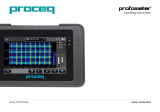
Fig. 1 Signal progression
during test impact
Hardness value L = 1000 · –
B
A
Time
Impact phase Rebound phase
This hardness value comprises a 3-digit value which
increases with the hardness of the tested material.
The L-value is additionally marked with the ID letter of
the respective impact device. For example: LU = 671
for the L-value of the impact device type U.
3.3 Measurement accuracy
The measuring accuracy of the PAROTESTER (EQUO
process) when using the L-value as a direct measure-
ment gauge:
4 Measurements

English
© 2012 Proceq SA
4 Technical data
4.1 Display device
Required batteries: 6 standard size AA cells:
1.5 V LR6
Operating time with a set of batteries at 20 ºC
approx.:
50 hours
Permissible ambient temperature range:
0 ºC to + 50 ºC
Connection sockets on the PAROTESTER
for impact devices:
2-pin and BNC
Connection for external power supply:
9 V DC 0.2 A
Data output socket:
RS 232 / DB 9p
Display device dimensions:
75 x 180 x 80 mm
Weight:
750 g, incl. batteries
- Medium measurement spread of the L-value over
the entire measuring range: ± 6 L based on the L-value,
L = 600: ± 1%
3.4 Impact device functional check
- The functional check of the PAROTESTER impact
devices and display devices is carried out electronically
with each measurement(impact energy and encoder
position).Corresponding messages are output on the
display in the event of deviation from the programmed
set value.
- An extended functional check of the impact devices
and display devices is carried out on a calibrated test
block. This serves for mechanical and electrical checks
of impact devices P, PG and U and display device
PAROTESTER2. These are carried out by measure-
ments on this test block. The PAROTESTER impact
devices and display device are working correctly when
the mean value of 3 to 5 measurements is within the
set value marked on the test block and the range R is
< 20 L . Also refer to the section 12.3 «Test block U».
Connecting the devices 5

. . © 2012 Proceq SA
4.2 Impact devices
Impact device type U
Impact energy: 200 Nmm
Max. penetration: 4.0 mm
Contact force: 120 N
Impact device diameter: 46 mm
Impact device length: 300 mm
Weight without cable: 890 g
Impact body U
Mass of the impact body 26 g
Calotte radius 25 mm
Impact body tip, hardened
Impact device type P
Impact energy: 160 Nmm
Max. penetration: 2.5 mm
Contact force: 100 N
Impact device diameter : 45 / 60mm
Impact device length: 300 mm
Weight without cable: 920 g
Impact body P
Mass of the impact body 20 g
Calotte radius 25 mm
Impact body tip not hardened
Impact device type PG
Impact energy: 90 Nmm
Max. penetration: 2.5 mm
Contact force: 100 N
Impact device diameter: 45 / 60 mm
Impact device length: 300 mm
Weight: 920 g
Impact body PG
Mass of the impact body 20 g
Calotte radius 25 mm
Impact body tip not hardened
Impact device type D
Impact energy: 11 Nmm
Max. penetration: 1.0 mm
Contact force ~10 N (by hand)
Impact device diameter: 20 mm
Impact device length: 150 mm
Weight without cable: 50 g
6 Connecting the devices

English
© 2012 Proceq SA
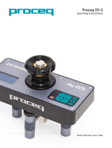
5.2 Impact device
Type U
5 Connections and controls
5.1 Display device
1. Operating panel
2. Large LCD with display of the L-values and
hardness curve
3. Signal input BNC
4. Signal input 2-pin
5. Carrying lugs
6. Signal output RS232C interface
7. Ext. battery connection 9 V DC 0.2 A
8 . Battery compartment, housing bottom section
9 . Battery compartment lid, housing bottom section
10. Housing top section
11. Housing bottom section
f Loading tube
f Guide tube
f Coil
f Support ring
f BNC cable
11
8/9
7
6
4
3
5
10 1
Connections and controls 7
2
Fig. 3
Fig. 2
Support ring
Type P/PG Type D
Cable
2-pin
f
Fig. 4 Fig. 5

. . © 2012 Proceq SA8 Operation of the devices
6. Device operation
6.1 Electronic display device
The display device is a user-friendly µP-controlled data
acquisition system with the following main advantages:
• Digital display and graphic recording of the measured
L-values
• Calculation of the mean value, standard deviation and
range
• Viewing all measured values in the entire memory
• Conversion to the R-value of the Schmidt - Hammer type
L / LR )
• Data memory with output option via RS232 (PC and
printer)
• Data input with barcode reader via RS232
• Multi-language capability
• Mains independent
Operating keys field and display field
Fig. 6 Fig. 7
Device on/off Cursor upwards Opens the menu
to menu level item on the menu level
Cursor to left Selection in menu level Cursor to right
right
Deletes last Cursor down Finishes menu input
measurement to menu level or concludes measure-
ment series
6.2 Connections
. Fig. 8
I I I I
1 2 3 4

English
© 2012 Proceq SA
6.3.1 Main necessary settings
The following 2 settings must always be checked and ad-
justed if necessary before recording the measured value.
These are:
1. Impact device type
2. Impact direction
On the ready for measurement screen the necessary set-
tings can be entered by pressing the «MENU» key. Move
the cursor to the «impact device» menu item ( Fig. 11 ).
Select the respective impact device with the arrow keys
and then confirm with the «MENU» key (Fig.12).
Press the «START» key a Select the impact device
Fig. 11 Fig. 12
After the «MENU» key is pressed for confirmation, the
main menu opens where the «Impact direction» menu
item can be selected with the cursor
1. Connection for external batteries or mains power sup-
plies 9 V DC 0.2 A
2. Connection RS232 9p, for external data output on PC,
printer or data input, barcode
3. Connection socket 2-pin
4. Connection socket BNC
6.3 Starting the devices
After pressing the «ON» key, the serial number of the
display device, the installed software version, date/time,
test Ok (Fig. 9) and the battery status in hours (approxi-
mate measurement duration) appears briefly on the dis-
play. The "ready for measurement" screen then appears
(Fig. 10).
After pressing the «ON» key a 4 – 5 s ready for measurement
Fig. 9 Fig. 10
Operation of the devices 9

. . © 2012 Proceq SA10 Operation of the devices
Press the «START» key a Setting a number
Fig. 15 Fig. 16
The following characters are available for the roll identi-
fication:
• Alphabetic character: A to Z
• Numeric characters: 0 to 9
• Special characters: [ : ] , [ - ],
• Spaces [ ]
PAROTESTER2 offers the option of setting works-related
roll identifications with a consecutive roll number (incremen-
tation).
Only left-justified input of a roll identification is possible.
Each character of the roll identification can be reached
with the arrow keys ( g / f ). A black square below the roll
identification [ ] shows whether the set characters are
alphabetic, numeric or special characters.
(Fig. 13) and selection is analog.
Press the «START» key a Select the impact direction
Fig.13 Fig.14
6.3.2 Other settings Roll number entry
On the PAROTESTER2 display device there are two
input types for the identifying roll numbers
1. Manual entry of a roll number
The maximum length of a roll identification is 14 or 25
characters. Roll numbers with 25 characters are only
possible from display device SN 511.XXXX onwards.
Press the «MENU» key to return to the main menu
(Fig.15). Select the «Roll number» menu item with the
cursor and press the «START» key. The last set roll
number is visible on this screen ( Fig. 16 ).
The cursor [ ] is always located at the left-hand edge of
the roll number if the «Roll number» menu item
is selected.

English
© 2012 Proceq SA
In addition the alphabetic, numeric and special charac-
ters can be pre-selected with the «CLEAR» key. The
vertical arrow keys ( h / i ) are used to set the required
characters at the current cursor position [ ].
Setting a consecutive number (incrementation) within
the roll identification
A consecutive number can be located anywhere in the
roll identification. A consecutive number is defined as
follows:
•The incremented number always starts with the
character [ : ].
• The end of an incremented number always finishes
with the character [ : ] or a space [ ].
Examples
•Roll identification; example 1: :1423: or :1423
•Roll identification; example 2: :10113:PAA - 2 - FR
•Roll identification; example 3: 123456AQS -
14AZ:009:A123AB
•Roll identification; example 4: A - BETA:0211:
or A - BETA:0211
The bold consecutive numbers are automatically
increased by 1 after each new measurement series/roll.
Each roll identification only permits one single consecu-
tive number!
Additional function of the space [ ]
The space [ ] also has an additional delete function.
All characters to the right of a space [ ] are deleted
when the END or MENU keys are pressed.
2. Electronic input of the roll number with the aid of
a barcode reader.
This electronic input is carried out with a barcode reader.
This option is possible from version SN 511.XXXX and
Eprom version 5.1. The barcode reader is an accessory
and is described in the respective section.
Display option
Press the «MENU» key to return to the main menu
where the «Display Option» menu item can be selected
with the cursor ( Fig. 17 ).
Operation of the devices 11

. . © 2012 Proceq SA12 Operation of the devices
( Fig.20 ). The mean value x: «727» is displayed in small
characters and the actual value «774» is in big charac-
ters ( Fig.21 )
Fig. 20 Fig. 21
From this position ( Fig.20 ) it is possible to use the arrow
keys h / i ) to switch the display of the mean value from
big to small and vice versa ( Fig.22 / 23 ). The mean value
x: «727» is displayed in big characters.
Fig. 22 Fig. 23
Press
a Select a Select
«START» key Display Option Display Option
Fig. 17 Fig.18 Fig.19
Display Option permits various settings on the display
( Fig.18 and Fig.19 ).
- The Y - axis can be displayed from the L Min = 100 to
L Max = 950 with programmable steps of ΔL = 50. The
respective values can be set at the respective cur-
sor position L Min and / or L Max with the arrow keys
( h / i ).
L Min and L Max are selected with the arrow keys
( g / f ).
- Display of the mean value and the current L - value is
possible in both large and small characters. To select
the large or small display of the mean value, press the
right arrow key ( g ). The cursor must be in the position
shown in Fig.18.
When the arrow key ( f ) is pressed, the cursor is on the
«Mean value» menu item.
The display of the mean value x : is set to «small»

English
© 2012 Proceq SA
Limit values
Press the a Select the limit values Example with
«START» key limit values
Fig.24 Fig.25 Fig.26
The limit values must be within the measurement range
( L = 100 to L = 950 ). If the cursor position is «0», the limit
values are not activated or not displayed.
Mean value
The maximum number of the measured values per roll is
200 measurements. All measured values
per roll are saved. PAROTESTER2 can upload the mea-
sured values automatically online to a PC or a printer
via interface RS232. To this purpose this automatic mea-
sured value output must be set.
Press the «MENU» key to return to the main menu
where the «Mean value» menu item can be selected with
the arrow keys ( h / i ) ( Fig. 27 ).
Press the = > Automatic Automatic
«START» key output: «off» output: «on»
Fig. 27 Fig. 28 Fig. 29
Automatic output is switched off; n = 0 ( Fig.28 ).
The measured values are then output and the respective
measurement series completed when the «END» key is
pressed.
Automatic output is switched on; n = XXX ( Fig.29 ).
The measured values are automatically output after XXX
measurements and the measurement series is concluded.
Conversion
General information on conversion:
PAROTESTER2 now features the option of comparing
the recorded PAROTESTER L - values with the R-values
of our Schmidt - Hammer type L / LR.
This comparison or conversion is only possible for paper
rolls and for the PAROTESTER impact devices type P
and type U.
Operation of the devices 13

. . © 2012 Proceq SA14 Operation of the devices
The hardness of a paper roll depends on a number of
parameters which can influence the hardness. For exam-
ple the quality of the cellulose, paper density, paper or
sheet thickness, temperature, moisture and naturally the
various parameters of the paper machines themselves
(rolling and unrolling speed, web tension, web guide etc.)
must be mentioned in this context.
All these parameters affect the measuring results of the
measuring devices to varying degrees. For these rea-
sons it is not possible to give any exact information on
conversion and the conversion range.
The aim of these conversions is:
- To permit switchover from the Schmidt process to the
improved PAROTESTER process.
- To provide direct comparison of the hardness values to
permit transfer of experience and specified quality crite-
ria from one system to the other.
Conversion settings:
Press the «MENU» key to return to the main menu
where conversion can be selected with the cursor ( Fig.
30 ).
Press the No conversion Conversion:
«START» key selected P
g LR selected
Fig.30 Fig.31 Fig.32
The respective conversion is set by pressing the arrow
keys ( h / i ) Fig. 31 / 32 .
The conversion of the L-values into R-values
( Schmidt - Hammer ) is only possible for the impact
device type U and type P. The selected conversion to the
R-value is shown on the display.
Date / time
Press the «MENU» key to return to the main menu where
the «Date/time» menu item can be selected with the
arrow keys ( h / i ) ( Fig. 33 ).

English
© 2012 Proceq SA
Press the «START» key a Day month, a year, month,
day setting year setting
Fig.33 Fig.34 Fig.35
The settings for the menu item «Date/time» can be easily
made with the arrow keys ( g / f ). The parameters can
be selected with the arrow keys ( h / i ) at the selected
position.
Language
Press the «MENU» key to return to the main menu
where the «Language» menu item can be selected with
the arrow keys ( h / i ) ( Fig. 36 ).
Press the «START» key a Language «English» selected
Fig.36 Fig.37
The required language can be selected with the arrow
keys ( h / i ).
7. Data output
Importantinformation on data storage or online data
upload
Data upload via the RS232C interface of the
PAROTESTER2 display device is only permitted with the
original PAROLINK3 cable or with the PC cable and is
also only possible when using such a cable.
If the PAROTESTER2 display device is connected to the
computer with any other commercially available cable,
faulty function, higher power consumption or permanent
damage of the PAROTESTER2 and the serial interface
of the computer can result.
Data output 15

. . © 2012 Proceq SA16 Data output
7.1 Transferring the memory
The following items are required for uploading the
memory contents to a personal computer:
- IBM - PC or compatible PC with a RS 232C connection
- PAROLINK3 cable with software protection
(Proceq cable)
- PAROLINK3 - Software Vers. 1.8X, Windows version
aW98 / Me / NT40 / Window 2000 / XP.
Memory capacity: approx. 150 rolls, each with 20 values.
Press the «MENU» key to return to the main menu
where the «Data output» menu item can be selected
with the arrow keys ( h / i ) ( Fig. 38 ).
Press the «START» key to enter the data output menu
( Fig.39 ).
Select the «Memory transfer» menu item with the arrow
keys
( h / i ).
Fig.38 Fig.39
Before starting the memory transfer (Memory transfer),
connect the PAROTESTER2 display device to the PC.
The red cable connector must be connected to the side of
the display device.
First start the PAROLINK3 and answer the necessary
PAROLINK3 questions
When the PAROLINK3
( Fig. 40 ) is ready,
press the «START» key.
Fig. 40

English
© 2012 Proceq SA
The following appears on
the display of the
display device ( Fig. 41 )
PAROTESTER2
Fig.41
Wait until data upload is finished and the data transferred
from the PAROLINK3 are shown on the screen.
7.2 Clear memory
Press the «MENU» key to return to the main menu
where the «Data output» menu item can be selected with
the arrow keys ( h / i ) (Fig. 42)Press the «START» key to
enter the data output menu ( Fig.42 ). Select the «Clear
memory» menu item (Fig.43) with the arrow keys ( h / i ).
Press the «START» key.
The clear function must be confirmed again by pressing
the «START» key (Fig 44). If you do not want to clear
the memory, press the «END» key.
Fig.42 Fig. 43
Fig. 44 Fig. 45
After pressing the «START» key twice, all data in the mem-
ory are permanently deleted ( Fig. 45 ).
Data output 17

. . © 2012 Proceq SA18 Data output
7.3 Online data transfer to the printer
( with serial interface RS232C )
Press the «MENU» key to return to the main menu
where the «Data output» menu item can be selected
with the arrow keys ( h / i ) ( Fig. 45).Press the «START»
key to enter the data output menu ( Fig. 46 ). Select the
«Online PC / Printer» menu item with the arrow keys
( h / i ). Press the «START» key. The online mode for PC
or printer can be selected with the arrow keys ( g / f ).
Online mode for the printer is selected by pressing the
«END» key ( Fig. 47 ).
Fig. 45 Fig. 46 Fig. 47
In online mode the measured data are transferred to the
printer after every roll or series of measurements. Online
transfer to the printer is carried out manually when the
«END» key is pressed or automatically.
Manual online transfer:
The data are always transferred manually when the
«END» key is pressed.
Printing options:
Press the «END» key 1x to print the hardness pro-
file, mean value, standard deviation ( ± s ) and range R
( R = Max - Min ) of the measurement series or roll.
Press the «END» key 2x to print the individual measured
values of the measurement series or roll.
The print options with the «END» key only
apply when n = 0 in the «Mean value» menu.
Automatic online transfer
The data are transferred automatically if the number of
measurements are pre-programmed. Entry of the num-
ber of measurements can be set in the «Mean value»
menu ( n = XXX ).
During automatic printing n = XXX, output on the printer is
identical to the output version A when the «END» key is
pressed 1x.
/