Page is loading ...

Proceq DY-2
Operating Instructions
Swiss Precision since 1954


© 2018 Proceq SA 1
Table of Contents
1. Safety and Liability .......................................................................2
1.1 Safety and Usage Precautions .............................2
1.2 Liability ...............................................2
1.3 Safety Instructions ......................................2
1.4 Compliance with Standards ...............................2
2. Standards and Equipment Selection ............................................3
2.1 Summary of the main pull-off testing standards................3
2.2 Proceq DY-2 Models .....................................4
3. Getting started ..............................................................................5
3.1 Charging the Proceq DY-2 ................................5
3.2 The Proceq DY-2 Operating Panel ..........................5
3.3 The Proceq DY-2 Menu...................................6
4. Test Parameter Settings ...............................................................6
5. Performing a Pull-Off Test with Proceq DY-2 ...............................9
5.1 Test Preparation ........................................9
5.2 Measurement Procedure.................................10
5.2.1 Peak load, test duration and effective load rate ...............11
5.2.2 Load rate warning ......................................11
5.3 Failure Mode Recording .................................12
5.4 Emergency Stop .......................................12
6. Accessories .................................................................................13
6.1 Working with large test discs .............................13
6.2 Working on vertical surfaces or overhead....................13
7. Ordering Information ..................................................................14
7.1 Units ................................................14
7.2 Test Discs and Accessories ..............................14
8. Technical Specifications .............................................................15
8.1 Maintenance and Support................................15
8.2 Standard Warranty and Extended Warranty ..................15
9. DY-Link Software ........................................................................16

2 © 2018 Proceq SA
1. Safety and Liability
1.1 Safety and Usage Precautions
This manual contains important information on the safety, use and maintenance of the Proceq DY-2.
Read through the manual carefully before the first use of the instrument. Keep the manual in a safe
place for future reference.
1.2 Liability
Our “General Terms and Conditions of Sale and Delivery” apply in all cases. Warranty and liability
claims arising from personal injury and damage to property cannot be upheld if they are due to one
or more of the following causes:
• Failure to use the instrument in accordance with its designated use as described in this manual.
• Incorrect performance check for operation and maintenance of the instrument and its compo-
nents.
• Failure to adhere to the sections of the manual dealing with the performance check, operation
and maintenance of the instrument and its components.
• Unauthorized structural modifications to the instrument and its components.
• Serious damage resulting from the effects of foreign bodies, accidents, vandalism and force
majeure.
All information contained in this documentation is presented in good faith and believed to be cor-
rect. Proceq SA makes no warranties and excludes all liability as to the completeness and/or ac-
curacy of the information.
1.3 Safety Instructions
The instrument is not allowed to be operated by children or anyone under the influence of alcohol,
drugs or pharmaceutical preparations. Anyone who is not familiar with this manual must be super-
vised when using the instrument.
1.4 Compliance with Standards
Proceq DY-2 complies fully with the standards listed in the next chapter.
Proceq DY-2 is calibrated according to EN ISO 7500-1 Annex C - Alternative Method of Testing
Machine Classification.
The software necessary to calibrate the instrument is included in DY-Link.

© 2018 Proceq SA 3
2. Standards and Equipment Selection
2.1 Summary of the main pull-off testing standards
Standard Description Test disc Specified load rate Total
test
time
EN 1542 Products and systems for
the protection and repair of
concrete structures - Mea-
surement of bond strength by
pull-off
Ø 50mm 0.05 ± 0.01 Mpa/s < 90s
EN 1015-12 Determination of adhesive
strength of hardened render-
ing and plastering mortars on
substrates
Ø 50mm 0.003 – 0.1 MPa/s 20-60s
EN 1348 Mortar for tiles and slabs.
Determination of the adhesive
strength of cement based mor-
tar for indoor and outdoor.
Ø 50mm 250 ± 50 N/s -
ISO 4624 Paints and varnishes - Pull-off
test for adhesion. Supercedes
EN24624 and NF T30-062
Ø 20mm < 1 MPa/s < 90s
BS 1881
Part 207
Recommendations for the as-
sessment of concrete strength
by near-to surface tests
Ø 50mm 0.05 ± 0.03 MPa/s -
ASTM D
4541
Standard test method for pull-
off strength of coatings using
portable adhesion testers
- < 1 MPa/s < 100s
ASTM C
1583
Standard test method for
tensile strength of concrete
surfaces and the bond strength
or tensile strength of concrete
repair and overlay materials by
direct tension (Pull-off method)
Steel
Ø 50mm
5±2 psi/s
0.035±.015MPa/s
-
ASTM D
7234-05
Standard test method for pull-
off adhesion strength of coat-
ings on concrete using portable
pull-off adhesion testers
Ø 20mm
Ø 50mm
Ø 75mm
< 0.2MPa/s, 30psi/s 5s to
30s
ASTM D
7522
Standard test method for pull-
off strength of FRP bonded to
concrete substrate
Ø 50mm
Ø 75mm
Ø100mm
< 1 MPa/min
< 150 psi/min
ZTV-ING The Federal Minister for
Transport. Additional technical
contract conditions and guide-
lines for engineering buildings
and the repair of concrete
components
Ø 50mm 100 N/s for concrete
300N/s for elastic
surfaces (Proceq
DY-206, Proceq DY-
216 recommended
for elastic surfaces)

4 © 2018 Proceq SA
Standard Description Test disc Specified load rate Total
test
time
SIA 281/3 Bitumen sheeting pull-off
testing
dia. 50mm 300
+/- 15 N/s
(Proceq DY-206,
Proceq DY-216
recommended for
elastic surfaces)
JGJ110 Construction Engineering dec-
orative tile Adhesive Strength
Testing Standard
JGJ126 The Exterior Decorative Brick
Construction and Inspection
Acceptance Standard
95x45x8mm,
40x40x8mm
JGJ144 Exterior Insulation Engineering
Technical Standard
100x100x8mm
2.2 Proceq DY-2 Models
Three versions of Proceq DY-2 are available differentiated by maximum pulling force.
• Proceq DY-206 has increased accuracy for low strength applications. Recommended for elastic
surfaces due to higher requirement on load rate.
• Proceq DY-216 covering most applications. Recommended for elastic surfaces due to higher
requirement on load rate.
• Proceq DY-225 required for compliance with ASTM C 1583. Typically used for testing of fibre
reinforced polymers bonded to concrete structures.
The table below shows the recommended working range with a selection of test discs to help you
ascertain which model is most suited to your application.
Working Range Maximum
Pulling Speed
Tensile Force Test Disc Ø 50mm
Proceq
DY-206
0.6 - 6 kN 0.3 - 3.1 MPa
4.65 mm/min
0.183 inch/min
135 - 1349 lbf 44 - 443 psi
Proceq
DY-216
1.6 - 16 kN 0.81 - 8.1 MPa
360 - 3597 lbf 118 - 1182 psi
Proceq
DY-225
2.5 - 25 kN 1.3 - 12.7 MPa 2.2 mm/min
0.086 inch/min
562 - 5620 lbf 185 - 1847 psi
Note: The instrument begins to display and record measurement values from 0 kN.

© 2018 Proceq SA 5
3. Getting started
Note: When shipped, battery packs are not fully charged. Prior to use, please charge
the battery completely. To prevent the battery from damage, avoid deep-discharging or
storing it long-term when empty. Store the instrument at room temperature and charge
the battery fully at least once a year.
3.1 Charging the Proceq DY-2
A fully charged battery is sufficient for approximately 80 complete load cycles.
The battery status symbol will be displayed when the accumulator is at 10% of its capacity. In this
case it is still possible to make measurements, but it is advisable to recharge the battery by con-
necting the unit to a wall adaptor or a PC via the mini-USB port on the rear of the instrument. A
complete charging cycle will take approximately 3 hours (longer in the case of a deep-discharge).
Note: When charging the battery or when operating on mains supply, the charging circuit
will be disconnected after 5 hours of continuous charging. This is a safety precaution.
The instrument will then turn off after a further 5 minutes.
A reserve battery pack (Part No. 346 10 220) may be purchased and held in reserve.
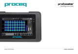
1
2
3
8
6
7
4
5
1 Hand wheel
2 Battery pack complete
3 Seal for battery
compartement
4 Cover plate for batte-
ry compartement
5 USB cover
6 Foot complete
7 Draw spindle
8 Coupling for the draw
bolt
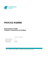
3.2 The Proceq DY-2 Operating Panel
Use the navigation keys to highlight a menu item and press the center key to select it.
Back button – Returns to the previous menu without making
any changes
2nd Function button – Access a 2nd function screen
Power button
The STOP button is used to stop the test at any time. See 5.4.

6 © 2018 Proceq SA
Operation - Power ON / OFF
• Power ON - Press the power button.
• Power OFF - It is only possible to power off from the main menu screen. If you are in any other
menu, press the back button to return to the main menu.
Press the power button once for the information screen showing the serial number, hardware
and firmware versions and the battery status:
Press the power button again to power off.
• Return to the main menu from the information screen by pressing the center key or the back button.
The instrument shuts down automatically after 5 minutes of inactivity.
3.3 The Proceq DY-2 Menu
On start-up the main menu screen will be shown.
Set Measurement
Unit
Start Test Memory
Select Test Disc
Diameter / Set Test
Disc Area
Set Load Rate
/ Set Maximum
Load
Set Date and Time
4. Test Parameter Settings
Note: The most current test settings are saved when the unit is powered off.
Setting the Units
• Choose between: lbf, kN, psi, N/mm2 and MPa.
• Press the center key to complete the action.
Note: Once the unit has been selected, the load rate selection will be defined in the same
unit. Load rate and disc size settings remain the same when switching from one unit to
another. The unit is converted automatically, e.g. 50 mm = 1.97”, 0.2 MPa/s = 29 psi/s

© 2018 Proceq SA 7
Set the Test Disc Size
For circular test discs:
• Enter the diameter of the disc.
• Press the center key to complete the action.
For square discs:
• Press the 2nd function key.
• Enter the surface area, e.g. for a 50x50 mm test plate, the surface area is 2500 mm2.
(Note the diameter setting will show a theoretically calculated value in this case.)
• Press the center key to complete the action.
Set the Load Parameters
Maximum applied load:
• To set a maximum applied load, press the 2nd function key.
• Enter the maximum load to be applied during the test. The minimum permissible setting for this
parameter is 20 % of the maximum value. If no maximum load is required, this should be set at
the maximum value supported by the instrument, i.e. 6 kN, 16 kN or 25 kN.
• Press the center key to complete the action.
Load rate:
• Set the load rate specified by the standard. If a load rate is not specified, a typical load rate of
100 N/s (22.5 lbf/s) may be selected.
• Press the center key to complete the action.
End of test criteria:
• To set the criteria for test completion, press the 2nd function key again. The default value is 80 %.
This means that the test will be completed when the load has dropped to 80 % of the peak load.
• When testing on softer or elastic materials it is possible that the test disc does not separate
completely from the substrate. Setting this parameter to 0 % will ensure that the instrument
continues pulling until the maximum stroke of 5mm is achieved.

8 © 2018 Proceq SA
Set the Date and Time
Every measurement is saved with a time stamp.
Set the date and time:
• Use the left and right navigation keys to select the item from either column.
• Use the up and down navigation keys to adjust the value.
• Press the center key to complete the action.
Measurement Memory
Memory can hold a maximum of 100 measurements.
When completely full, the oldest will be overwritten.
To review the saved measurements follow the procedure below:
• Choose the memory icon.
• Choose the icon to review the measurements.
• Scroll to the desired measurement and press the center key to see the measurement details.
ID Time Stamp
Peak Load max Load
Rate
Diameter
Area
Test Duration
Effective
Load Rate
• Press the left and right navigation keys to switch between the main test result (see above) and
the failure mode reporting screens (see below).
Details see chapter 5.3.

© 2018 Proceq SA 9
Measurement ID
The measurement ID may be set by the user. The ID is incremented after each measurement.
• Press the center key to complete the action.
Deleting all saved objects
• Press the center key to delete.
• Press the back button to escape without deleting.
5. Performing a Pull-Off Test with Proceq DY-2
Proceq DY-2 is designed to make it very easy to work according to the various standards for pull-
off testing. It allows the user to specify a load rate and provides a graphical display (via DY-Link
software) of the effective load rate achieved during the test. The standards vary according to the
purpose of the pull-off test and the types of material under test. (See the list in Chapter 2). Typically,
the key test parameters are:
• The size of the test disc
• The load rate applied to the test disc
• The total time allowed for the test
5.1 Test Preparation
Pull-off testing is used on many different types of materials. The actual test parameters should be
taken from the specified standard as noted below.
• Preparation of the test disc. Depending on the material under test, it may be necessary to
roughen the surface using emery paper to ensure good adhesion. It is also advisable to remove
any grease from the surface.
• Gluing the test disc to the surface under test. The type of adhesive will vary with the applica-
tion, but typical adhesives used are:
- Devcon 2 Ton Epoxy
- Loctite 907, Loctite 3430
- Sikadur 30, Sikadur 31
- Araldite Regular/Rapid
• Isolation of the test area by partial coring, or cutting. Typically a coring bit of the appropriate
size (e.g. 50mm) is used to drill through the coating and into the concrete substrate. (E.g. EN
1542 recommends 15mm into the substrate).

10 © 2018 Proceq SA
Core Test disc
• Waiting for the adhesive to set.
• Fixing the draw bolt to the test disc. (Proceq DY-2 test discs use a 10mm draw bolt. 8mm and
12mm draw bolts are also available).
• Fit the draw bolt to the coupling.
This completes the test preparations.
Note: When measuring on perfectly horizontal or vertical surfaces a spirit level may be used if desired
to check the alignment of the pull-off tester. Correct alignment may be achieved by adjusting the
screws on the legs. If the surface is inclined, this method is not practical.
5.2 Measurement Procedure
Press the center key to begin.
Verify settings. (Note: In the case of square discs, the diameter is a
theoretical value.)
Parameters can only be reviewed. To make changes, press back to re-
turn to main menu.
Pre-loading. Turn the hand wheel to take up the slack on the test disk
until a force (>0) is indicated as a blinking measurement. The force ap-
plied is minimal.
Press the center key to start the test.
The measurement screen indicates the increase in load.
A nominal load rate is applied until a force of 250 N (56 lbf) is applied.
At this point the programmed load rate is applied for the duration of
the test.

© 2018 Proceq SA 11
On completion of the test the summary screen shows the peak load,
test duration and the effective load rate. The motor winds back auto-
matically ready to begin the next test.
Press the center key to enter “Failure Mode Recording”. (See below.)
Press on save to complete the test and return to the main menu.
If you do not wish to save the test, select the delete icon and press the
center key to return to the main menu.
Note: If you do not wish to record the failure mode, simply press on save to complete the
test. The test will be saved and you will return to the main menu.
5.2.1 Peak load, test duration and effective load rate
The peak load is the maximum load achieved during the test.
The test duration begins when the load reaches 250 N (56 lbf) (load rate control begins) and ends at
the time when the end of test criteria is reached. If this is set to 0 % this can be misleading. Look at
the graphical output in this case for confirmation.
The effective load rate is calculated from the point at which load rate control begins (250N) to the
time at which 80 % of the peak load is reached. (This is done to avoid inconsistencies in load rates
caused by non-clean breaks when elastic and thermoplastic materials are being tested.)
5.2.2 Load rate warning
Pull-off testing from a single side, is best suited for rigid substrates. Deformable substrates or elas-
tic coatings can lead to a falsification of the results of a pull-off test. Proceq DY-2 provides the tools
to help in the analysis when testing on such materials.
If the load graph appears on the measurement screen as a blinking icon during a test, it indicates
that the programmed load rate cannot be achieved.
The most likely cause of this is due to plastic deformation of either the substrate or the material
under test or the selection of a load rate beyond the capabilities of the instrument (see technical
specifications).
It is recommended in this case to store the test result and download it to DY-Link for detailed
analysis.

12 © 2018 Proceq SA
5.3 Failure Mode Recording
Many standards also require the user to record the mode of failure in varying degrees of complex-
ity. Proceq DY-2 allows the user to record the failure mode with the test result for comprehensive
reporting. The possibility to record the failure is flexible enough to accommodate the requirements
of the various standards.
e.g. ISO 4624 failure mode reporting classification.
• A is a cohesive failure of the substrate;
• A/B is an adhesive failure between the substrate and the first coat;
• B is a cohesive failure of the first coat;
• B/C is an adhesive failure between the first and second coats;
• etc.
• Estimate the area of fracture as a percentage to the nearest 10% for each type of fracture.
The first column indicates where the break took place. The second column indicates the percentage
of the break in that particular layer.
For simplified reporting as specified for example in ASTM C 1583, then the user would enter for
example B 100% indicating a failure at the first coating.
• Use the navigation keys to select the item from either column.
• Define your own classifications for A, B, etc.
• Use the center key to alter the value.
5.4 Emergency Stop
In case of an emergency the red-colored STOP button can be pressed. The instrument stops in any
case and the following dialog appears:
• Selecting the "Rewind" icon lets the instrument move back to its starting postition.
• Selecting the "Cancel" icon lets you return to the main menu without any movement of the motor
and you may proceed with the test.

© 2018 Proceq SA 13
6. Accessories
6.1 Working with large test discs
The standard Proceq DY-2 configuration can be used with test discs up to 50mm diameter or 50 x
50mm square.
Adapter plate for large test discs
The adapter plate (Part No. 346 10 530) accommodates all test discs in the Proceq range.
Note: When working with the adapter plate the maximum load must not exceed 16kN.
(See Chapter 4 - “Set the Load Parameters”).
6.2 Working on vertical surfaces or overhead
When working on vertical surfaces or overhead ensure that the test disc is firmly glued to the sur-
face before coupling the Proceq DY-2. When the test is completed the instrument will fall unless
properly supported either by hand or by a mechanical fixing.
An optional fixing kit is available for this purpose (Part No. 346 10 550).
Warning! The operator is responsible for making sure that the instrument cannot fall and
cause damage or injury.

14 © 2018 Proceq SA
7. Ordering Information
7.1 Units
Part No. Description
346 10 000 Proceq DY-206 Pull-off tester 6 kN (1349 lbf) including: battery pack, battery charger
with USB-cable, test disc aluminium Ø 50mm/M10, draw bolt M10, torx screwdriver,
software, operating instructions, calibration certificate and carrying case
346 20 000 Proceq DY-216 Pull-off tester 16 kN (3597 lbf) including: battery pack, battery char-
ger with USB-cable, test disc aluminium Ø 50mm/M10, draw bolt M10, torx screw-
driver, software, operating instructions, calibration certificate and carrying case
346 30 000 Proceq DY-225 Pull-off tester 25 kN (5620 lbf) including: battery pack, battery char-
ger with USB-cable, test disc aluminium Ø 50mm/M10, draw bolt M10, torx screw-
driver, software, operating instructions, calibration certificate and carrying case
7.2 Test Discs and Accessories
346 10 500S Test disc steel, Ø 50mm/M10, set of 10
346 10 501S Test disc aluminum, Ø 50mm/M10, set of 10
346 10 502S Test disc aluminum, Ø 20mm/M10, set of 10
346 10 503S Test disc aluminum, 50x50mm/M10, set of 10
346 10 504S Test disc aluminum, 40x40mm/M10, set of 10
346 10 505S Test disc aluminum, Ø 100mm/M10, set of 3
346 10 506S Test disc aluminum, 100x100mm/M10, set of 3
346 10 507S Test disc aluminum, Ø 75mm/M10, set of 5
346 10 250 Draw bolt M10 short for Proceq DY-2
346 10 520 Draw bolt M8 short for Proceq DY-2
346 10 521 Draw bolt M12 short for Proceq DY-2
346 10 530 Adapter plate for large test discs
346 10 220 Battery pack complete
346 10 550 Fixing kit for vertical and overhead surfaces
Note: Proceq test discs require an M10 draw bolt. The M8 and M12 draw bolts are for
use with test discs not supplied by Proceq. For the 25kN instrument an M10 draw bolt is
required for forces above 16kN.

© 2018 Proceq SA 15
8. Technical Specifications
Maximum Tensile Force Maximum Pulling Speed
Proceq DY-206 6 kN
4.65 mm/min
0.183 inch/min
1349 lbf
Proceq DY-216 16 kN
3597 lbf
Proceq DY-225 25 kN 2.2 mm/min
0.086 inch/min
5620 lbf
Max stroke 5 mm
Calibration accuracy EN ISO 7500-1 Class 1 (±1% from 20% of max. Force)
Memory capacity 100 measurements
Battery capacity 1500 mAh, 3.7V (min. 80 measurements)
Charger connection USB type A (5V, 500mA)
Weight 4.5 kg
Dimensions of housing 109 x 240 x 205.5 mm
Operating temperature -10 to 50°C (14 to 122°F)
Storage temperature -10 to 70°C (14 to 158°F)
IP classification IP54
8.1 Maintenance and Support
Maintenance
To ensure reliable and accurate operation, it is recommended to have the instrument serviced and
re-calibrated on a yearly basis. Customers may however determine their own service interval based
on application and usage. The instrument assists with determining a suitable interval by giving a
warning on start-up after 1500 complete test cycles.
Support Concept
Proceq is committed to providing a complete support service for this instrument by means of our
global service and support facilities. It is recommended that the user register the product on www.
proceq.com to obtain the latest on available updates and other valuable information.
8.2 Standard Warranty and Extended Warranty
The standard warranty covers the electronic portion of the instrument for 24 months and the me-
chanical portion of the instrument for 6 months. An extended warranty for one, two or three years
for the electronic portion of the instrument may be purchased up to 90 days of date of purchase.

16 © 2018 Proceq SA
9. DY-Link Software
Installing DY-Link
Locate the file “DY-Link Setup.exe” on your computer or on the CD and click on it.
Follow the instructions you see on the screen.
Make sure that the “Launch USB Driver install” tick is selected.
Starting DY-Link and viewing data stored on Proceq DY-2.
Double click on the DY-Link icon on your desktop or start DY-Link via the start menu.
DY-Link starts with a blank list.
Application settings
The menu item “File–Application settings” allows the user to select the language and the date and
time format to be used.
Download Data
Connect the Proceq DY-2 to a USB port, then click on this icon to download all data
from the instrument.
Click on the double arrow icon in the “Slot No.” column to see the load rate graph.

© 2018 Proceq SA 17
Note: Click on “Add” to attach a comment to the object.
DY-Link also provides the user with a “Sum mary” window. This is useful for comparing a series of
tests.
To include or exclude a measurement from the summary, click on the summary symbol in the Slot
ID column. This symbol is either “black” or “greyed out”, which shows whether or not the measure-
ment is included in the summary. In order to make a sum mary, all selected series have to have the
same unit.
Exporting data
DY-Link allows you to export selected objects or the entire project for use in third party programs.
Click on the measurement object(s) you wish to export.
Click on the “Export measurements to CSV file(s)” icon. The data for this measurement
object(s) is exported as a Microsoft Office Excel comma separated file or files. The
export options may be chosen in the following window.
Click on the “Export measurements as graphic file(s)” icon to open the window which
allows the various export options to be chosen.
In both cases, a preview window shows the effects of the current output selection.
Finish by clicking on export to select the file location, name the file and in the case of a graphical
output to set the output graphic format: .png, .bmp or .jpg
Data editing
The menu item “Edit” allows you to "select all", "copy", "paste" and "delete" measurements from
the downloaded data.

18 © 2018 Proceq SA
Alternatively you can also right click on one or more measurement rows to invoke the context menu
which allows you to "cut", "copy", "paste" or "delete" the selected measurements.
For each measurement you can modify the following fields:
• ID (double click)
• Date & Time (right click)
• Unit (right click)
Deleting data stored on the Proceq DY-2
Select the menu item “Device – Delete all measurements object on Proceq DY-2” to delete all data
stored on the Proceq DY-2. A warning will be given when all of the data is about to be deleted.
Confirm to delete. It is not possible to delete individual series.
Further functions
The following menu items are available via the icons at the top of the screen:
“PQUpgrade” icon - Allows you to upgrade your firmware via the internet or from local
files.
“Open DY-link project file” icon – Allows you to open a previously saved .pqr project.
“Save project” icon – Allows you to save the current project.
“Print” icon – Allows you to print out the project. You may select in the printer dialog, if
you want to print out all of the data or selected readings only.
It is also possible to select one of more measurements and copy and paste them between project
files using CTR-C and CTRL-V.
Live View Mode
The Live View Mode allows the user to monitor the load increase in real-time when the Proceq DY-2
is connected to a PC.
Note: Once the Live View Mode has started, any changes to the settings on the device
(e.g. load rate, max load, unit, dolly area) will not be reflected in the measurement plot
until the Live View Mode is stopped and restarted.
/