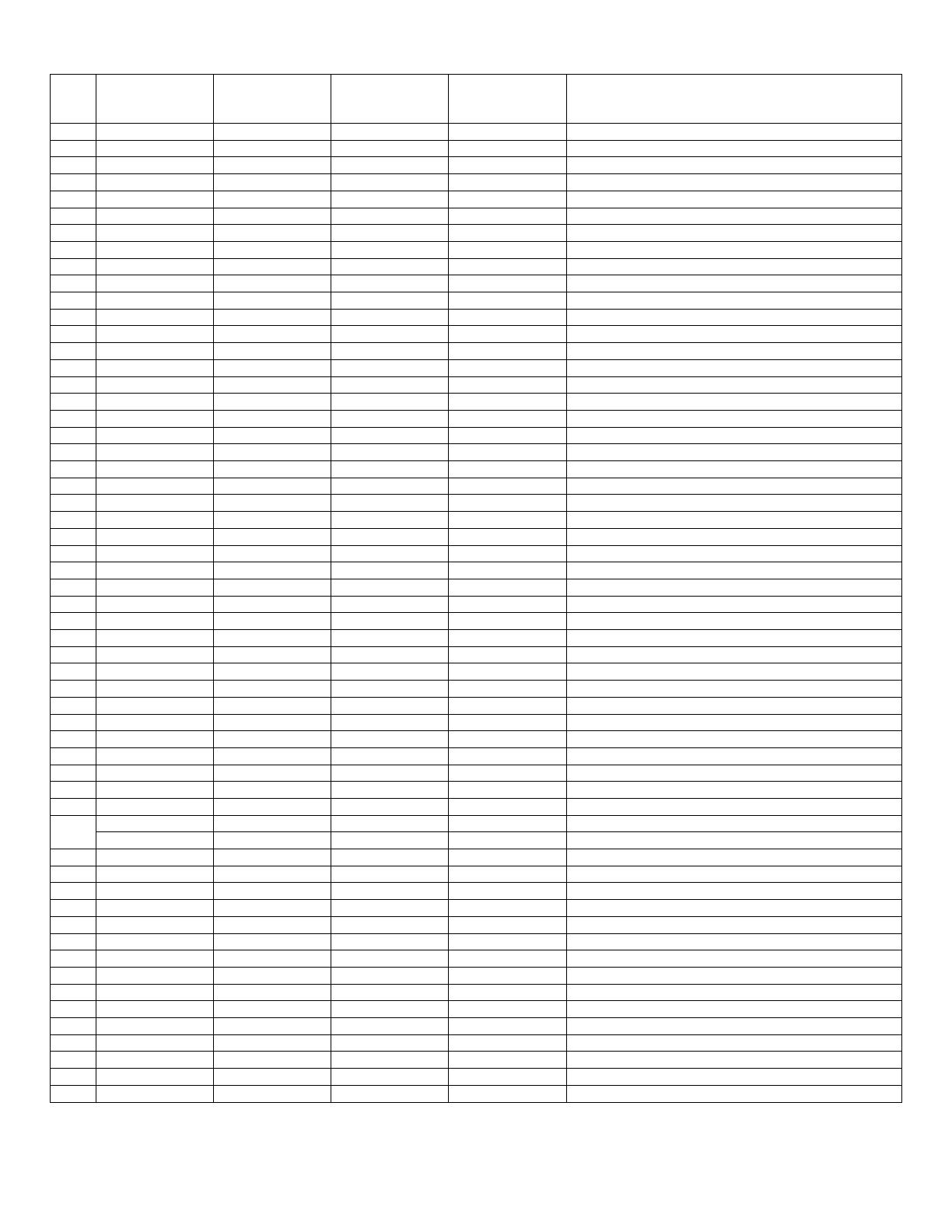
Essick Excel RN46W Owner's manual

Category
Split-system air conditioners
Type
Owner's manual
1
Owner’s Manual
Model #’s
WC35, RWC35
N35W, RN35W
WC44, RWC44
WC46, RWC46
N46W, RN46W
WC50, RWC50
N50W, RN50W
Read & Save This
Instruction Manual!
Window Evaporative
Air Cooler
Evaporative Cooling
Evaporative cooling uses the principle of evaporation to lower the air
temperature. Hot, dry air is passed through wetted filters and is converted to
refreshingly cooled air. Champion/Essick coolers make the best use of the
evaporative process by controlling the flow of water, spreading the water evenly
over the filters, and keeping a steady stream of cooled air entering your home.
It is exhausted out open windows or doors, carrying heat, smoke and odors
along with it. Champion/Essick evaporative coolers are 80% less costly to
operate than refrigerated air conditioners.
P/N 71088
REV 1/06
2
SAFETY GUIDE LINES & CAUTIONS
When Installing When Operating When Servicing
Make sure that unit is installed on a sound
structure that will support the full operating
weight of the cooler. See page 4.
Make sure that circuit cooler is plugged into is
equipped with a (slow blow) breaker large
enough to support the full amperage of the
cooler.
Always Unplug the cooler before attempting
service of any kind.
Before attempting to hang the cooler in the
window, remove the louvers to reduce weight.
To reduce the risk of fire or electrical shock, DO
NOT use this fan with any Solid-state speed
control device.
Be sure to disconnect unit from power
source before servicing. If not, it can be
turned on from inside the house and start
unexpectedly.
Do NOT connect power to cooler before
installation is complete.
This cooler is equipped with an
UUUUautomaticUUUU
thermally protected motor. If it shuts off on its
own for any reason,
UUUUit can restart without
warningUUUU.
If the motor shuts off because of thermal
overload, check into the problem
immediately. If allowed to continue,
permanent damage will occur.
MOUNTING
To install this cooler, the following tools are required:
Adjustable wrenches
Screwdrivers
Electric drill
3/16” drill bit
Level
1. Loosen the Adjustment Screw in the Stand-Off Bracket. Remove the Spacer-Rod
from the installation package and insert them into the Stand-Off brackets as shown.
2. Cut the Side Sealer Channels so that two of them will span the window when
butted together. Place two of the channels on the bottom duct flange as shown.
3. Place the Cooler in the center of the window with the bottom duct flange resting
against the sill.
4. Pull out the Spacer-Rods so as to allow the Rubber Feet to rest against the side of
the house. Tighten the Adjustment Screws.
5. Lower the window to rest on top of the duct behind the top duct flange.
6. Fasten a stop above the inside window sash to prevent the window from being
raised. Raising the window may cause the cooler to fall.
7. Adjust the Spacer-Rods to level the cooler. This will ensure proper water flow to the
pads.
8. Install the Chain Supports.
a. Drill pilot holes in the window frame, 3 feet above the top of the duct and the width
of the cooler apart. Install the Screw-Hooks in these pilot holes to the full depth of the
thread.
b. Hook one end of each Chain over each Screw-Hook.
c. Place S-Hooks in the in the holes at the top-rear of the cooler.
d. Place the opposite end of the S-Hooks in the free end of each Chain. Make sure
the chains are taut, but not so tight they pull the bottom of the cooler away from the
wall.
9. Install the Side Sealer Panels. These panels are the correct height, but need to be
trimmed to fit the width of your window. Trim the panels so that they reach from the
window frame to the side of the duct. Slide the panels in the channels you placed on
the bottom duct flange. Install the remaining Side-Sealer Channels over the top duct
flange and the Side-Sealer Panels.
3
INSTALL OVERFLOW AND DRAIN
1. Slide the Rubber Washer over the Drain Bushing and push through the hole in the
bottom of the cooler from the top side.
2. Secure the Drain Bushing from beneath the pan with the Lock Nut. Make sure the
Rubber Washer does not twist while tightening, which could cause it to leak.
UUUUDO NOT
OVERTIGHTEN.UUUU
3. Thread the Overflow Tube into the Drain Bushing and HAND TIGHTEN.
4. If leakage occurs after Reservoir is full, retighten the Overflow Pipe until leaking stops.
A small amount of silicone caulk may be used if necessary.
FLOAT VALVE INSTALLATION
1. Place the threaded portion of the Float Valve through the hole provided in the Corner
Post from the inside.
2. Slip the Fiber Washer over the threaded portion outside the corner post and secure with
the Nut. Be sure the Float does not turn while you are tightening the Nut.
WATER LINE CONNECTION
Find the closest outside water faucet, and install a Water Connection Kit (not included with
cooler) as shown. If an exterior faucet is not available, locate the closest cold water pipe
and install a saddle valve assembly.
Route tubing to cooler. Place Compression Nut and Ferrule over end of tubing. Insert the
tubing into float valve and tighten Compression Nut to secure. NOTE: Over tightening the
compression fitting will cause that fitting to leak. It is best to secure the connections, turn
on the water, and then snug the fitting until leaking stops.
ADJUSTING WATER LEVEL AND FLOAT VALVE
To adjust water level, bend the float valve rod.
Check all water connections for leaks.
Make sure the Float Valve cuts off completely when the desired water level has been
reached (½” to ¾” below top of Overflow Tube). If the float does not stop the water
completely, the water level will rise and run out the Overflow Tube.
Double check the Overflow Tube for leaks.
START UP
1. Plug in the electrical cord to a standard grounded receptacle. Be sure the Circuit Breaker protecting the receptacle is of
sufficient size.
2. Open windows in rooms where you want cooling to be directed.
3. Turn the cooler to the High Fan position. Observe the amount of air being delivered. Note: on cool nights (or days) or
when the humidity level is high, the fan positions may be used for ventilation purposes.
4. Turn the cooler to the Low Fan position. This should significantly reduce the amount of air being delivered.
5. Turn the cooler to the Pump Only position. The pump should run and not the fan. Check to see that water is flowing
from all three Water Trays.
6. Turn the cooler to the High Cool position. Check to see that all three Pads are wetting evenly with no dry patches. The
Pads may take up to 20 minutes to wet fully. If the Pads have dry patches, you can adjust the level of each Water Tray
by screws on each end.
7. Adjust window openings to achieve desired cooling level.
Reservoir
Ferrule
Faucet
4
WIRING DIAGRAM
CAUTION: Always unplug cooler before opening or attempting service of any kind.
WARNING: To reduce the risk of fire or electric shock, do not use this fan with any solid-state speed control device.
COOLER SPECIFICATIONS
Model Height Width Depth Amps Shipping Weight Operating Weight
(R)WC50/(R)N50W 35” 34” 34” 8.4 165 249
(R)WC46/(R)N46W 35” 34” 34” 7.4 165 249
(R)WC44 35” 34” 28” 7.4 147 217
(R)WC35/(R)N35W 31” 32” 21” 7.4 135 184
TROUBLE SHOOTING
Problem Cause Remedy
Motor cycles on and off
Excessive belt tension
Blower shaft not spinning freely
Extension cord (if one used) too long
Circuit breaker not large enough
Adjust belt tension
Lubricate or replace bearings
Choose a shorter or heavier gauge cord
Consult a licensed electrician
Fails to start
No electrical power
Circuit breaker tripped or fuse blown
Check all electrical connections and cords
Reset circuit breaker or replace fuse
Water draining from overflow
Float improperly adjusted Adjust float
Blower vibrates excessively
Belt or pulley loose
Blower wheel out of balance or out of
alignment
Debris in blower housing
Adjust belt or tighten pulley
Replace the blower wheel
Clear debris
Not cooling
Blocked water lines
Windows opened too little or too much.
Uneven pad wetting
Pump clogged or failed
Pads plugged with dirt and water deposits
Check incoming water line, float and water
distributor for blockages and clear.
Adjust window openings
Level water trays, check for blocked water
slots in water trays
Clean or replace pump
Replace pads
This cooler is equipped with an UUUUautomaticUUUU thermally protected motor. If it shuts off on its own for any reason, UUUUit
can restart without warningUUUU.
Your cooler may be controlled by a rotary switch (MANUAL CONTROLS) or by a touch pad/remote control. See below for
functions.
Note: pressing the ON/OFF button while the unit is running will turn off power to the entire unit. Pressing the button again
will turn the unit back on at the same setting, which the unit was at when it was turned off.
Switch Operation Remote Control Operation
OFF Fan off Pump off
PUMP ONLY Fan off Pump on
ON/OFF
Controls power to unit. Does not change fan speed or turn
Pump on or off.
HIGH COOL Fan high speed Pump on
LOW COOL Fan low speed Pump on
FAN
Controls Fan speed. Press once for high speed (HI light on).
Press again for low speed (LO light on). Press again to turn
fan off (HI and LO lights off).
HIGH VENT Fan high speed Pump off
LOW VENT Fan low speed Pump off
PUMP
Controls Pump. Press once for pump on (PUMP light on).
Press again for pump off (PUMP light off).
Black - Hi
Red - Low
White - Common
Green - Ground
Motor
Pump
Switch
Wiring Harness
Motor Cord
Manual Control
5
MAINTENANCE
NOTE: The fan motor is thermally protected with an automatic reset and will
automatically stop if overloaded. After the motor cools, it will restart automatically.
If this occurs, check into the problem before permanent damage occurs.
Once a month during cooling season, inspect your cooler for leaks, proper belt
tension and alignment, blocked water lines and excessive residue build-up on the
pads.
To adjust belt tension, loosen the 4 Adjustment Bolts (2 each side) on the Motor
Mount. Adjust belt tension so that 3 pounds of pressure (lightly push with one
finger) will cause the belt to deflect ¾”, as shown. Retighten the Adjustment
Bolts.
Use SAE 20W or SAE 30W non-detergent oil to lube the bearings. Place 2 to 3
drops in the bearing oil cups at the beginning of the season and no more than once a
season during cooling season. If the motor has oil holes (usually plugged with yellow
caps that read “OIL” at either end of the motor) oil the motor also, following the same
procedure as for bearings.
NOTE: Excessive oil in the bearings may leak out and be drawn into the air stream.
Excessive oil in the motor may leak onto the motor windings and damage the motor.
Do NOT oil bearings prior to initial start-up.
To replace pads
1. Remove louver from cooler.
2. Unhook pad holders and remove.
3. Remove and discard old pad.
4. Clean water deposits from the louver. If the paint is chipped or rust spots occur, sand
the spots and paint louver with a rust resistant exterior paint.
5. Place new filter in louver and tuck in to prevent hot air from bypassing.
6. Replace pad holders and hook into place.
7. Replace louver in cooler.
NOTE: It is best to replace filter pads
UUUUat the end of the seasonUUUU. Old filter pads
soak up lime and salts that can rust louvers and the cabinet during the wet,
rainy winter months.
At the end of the season
1. Remove the Overflow Tube and let the water drain from the reservoir.
(The bushing is threaded to accept a standard garden hose. If desired, a
garden hose may be used to route water away from your house.)
2. Rinse dirt and debris from the pan and clean any water deposits that may
have collected in the reservoir or on any interior surface of the cooler.
3. If the paint is chipped or rust spots occur sand the spots and paint with a
rust resistant exterior paint.
4. Replace the Overflow Tube when you start the cooler for the next season.
NOTE: Do not get water on the Fan Motor or Pump Motor. This will cause damage.
If freezing weather occurs in your area, it is best to shut off the water supply at the source and drain the supply line to
the cooler.
A canvas cooler cover is recommended to prevent rain and weather from damaging your cooler.
To prevent the Shaft from rusting, coat with a wax based lubricant. Allow Lubricant to dry completely and all fumes to
disperse before turning on the cooler.
3/4"
6
Repair Parts
Item
WC35, N35W
RWC35, RN35W
Part No.
WC44
RWC44
Part No.
WC46, N46W
RWC46, RN46W
Part No.
WC50, N50W
RWC50, RN50W
Part No.
Description
1 70735 70738 71090 71090 Top
2 70737 70740 70740 70740 Front
3 70736 70739 70759 70759 Bottom
4 504242 504245 504245 504245 Corner Post Plain
4* 504243 504246 504246 504246 Corner Post – W/Float Valve Hole
5 70808 70808 70808 70808 Duct
6 70806 70744 70744 70744 Blower Housing
7 30318 30322 30322 30322 Blower Wheel
8 30241 30238-02 30238-02 30238-02 Blower Shaft
9 501244 501241 501241 501241 Fiber Washer
10 524330 524331 524331 524331 Set Collar
11 583000 60PB 60PB 60PB Bearing
12 583009 583091 583091 583091 Blower Pulley
13 582093 582030 582030 582030 Belt
14 504302 504289 504296 504296 Blower Brace
15 515160 512574 512574 512574 Motor Mount
16 595121 595121 595121 595121 Motor Cord
17 524162 524162 524162 524162 Motor Saddle Clamps
18 581188 581188 581188 50310 Motor
19 31085 31085 31085 16579 Motor Pulley
20 *** *** *** *** Water Tube Holder
21 598474 598474 598472 598472 Water Hose
22 512551 512550 512548 512548 Water Distributor
23 71098 70488 70488 70488 Pump Bracket
24 506669 506669 506669 506669 Pump
25 70613 70613 70613 70613 Overflow Kit
26 504253 504254 504256 504256 Pad Retainer (Side)
26 504255 504256 504256 504256 Pad Retainer (Back)
27* 141N 120N 71099 71099 Filter Set
27 516153 516157 503314 503314 Filter (Side)
27* 516155 503314 503314 503314 Filter (Back)
28 504258 504262 504263 504263 Louver (Side)
28* 514260 504263 504263 504263 Louver (Back)
29 504266 504267 504269 504269 Water Tray (Side)
29* 504268 504269 504269 504269 Water Tray (Back)
** 70940 70944 70945 70945 Louver Assembly (Side)
** 70941 70945 70945 70945 Louver Assembly (Back)
30 70655 70655 70655 70655 Wiring Harness (manual units only)
31 524299 524299 524299 524299 Switch (manual units only)
32 70664 70664 70664 70664 Knob (manual units only)
33 70798 70798 70798 70798 Switch Bracket (manual units only)
70658 70658 70658 70658 Grill Frame, manual control units
34
71145 71145 71145 71145 Grill Frame, remote control units
35 70741 70741 70741 70741 Sub-Vent Assembly
36 70925 70924 70924 70924 Bearing Support
37 70667 70667 70667 70667 Grill Cover (Sold separately)
38 70656 70656 70656 70656 Side Sealer Channel
39 70618 70618 70618 70618 Side Sealer
40 524344 524344 524344 524344 Rubber Foot
41 504341 504341 504341 504341 Spacer Rod
42 504337 504337 504337 504337 Stand-Off Bracket
43 502389 502389 502389 502389 Float
44 70801 70801 70801 70801 Pump Basket
* 70804 70804 70804 70804 Duct Mount Strip
45 71113 71113 71113 71113 Dress Ring (remote units only)
46 71114 71114 71114 71114 Electronic Control Assembly (remote units only)
47 71115 71115 71115 71115 Lock Plate (remote units only)
48 71116 71116 71116 71116 Remote Control (remote units only)
* Item not shown
** Contains louver, water tray, pad and pad retainers
*** Not used
7
23
Models/Modelos:
RWC35/RN35W,
RWC46/RN46W,
RWC50/RN50W
Models/Modelos:
WC35/N35W,
WC46/N46W,
WC50/N50W
8
Instructions to Convert Unit to Vertical Duct Configuration
1. Remove the 13 screws holding the Duct in place.
2. Replace the 4 screws removed from the Top Pan.
3. Turn the Duct 90 degrees counter-clockwise. Be careful not to unplug the switch from the wiring harness.
4. Align the Duct with the 3 holes at the top of the Front Panel (just below the Top Pan).
5. Insert 3 screws at the top and bottom of the duct.
6. Place the Duct Mount Strips (found in bottom of cooler) over the side Duct Flanges and insert screws 3 each side into
the holes provided (3 screws will be in installation kit).
Proceed with the installation as normal. The Side Sealer Channels will go on the same flanges as for a horizontal duct.
You may use the Side Sealers provided to close off the window above your cooler’s duct.
LIMITED WARRANTY
This warranty is extended to the original purchaser only. It does not cover damages incurred during shipping or
through accident, neglect, or abuse by the owner. Champion Cooler/Essick Air Products does not authorize any person
or representative to assume any other or different liability in connection with this cooler.
TERMS AND CONDITIONS OF WARRANTY
The BOTTOM PAN is guaranteed against leakage due to rusting out
for Eight Years. All other original parts provided
by Champion Cooler/Essick Air Products are warranted against defects in material or factory workmanship for One Year.
EXCLUSIONS FROM THE WARRANTY
Champion Cooler/Essick Air Products is not responsible for incidental or consequential damage resulting from any
malfunction.
Champion Cooler/Essick Air Products is not responsible for any damage occurring from the use of water softeners,
chemicals, descale material, or if a higher horsepower motor than what Champion Cooler/Essick Air Products
recommends is used in the unit.
Champion Cooler/Essick Air Products is not responsible for the cost of service calls to diagnose cause of trouble, or labor
charge to repair and/or replace parts.
HOW TO OBTAIN SERVICE UNDER THIS WARRANTY
Contact the Dealer where you purchased the evaporative cooler. If for any reason you are not satisfied with the response
from the Dealer, contact Customer Service Department: Essick Air Products Inc. 5800 Murray Street, Little Rock,
Arkansas 72209. 1-800-643-8341.
  • Page 1 1
  • Page 2 2
  • Page 3 3
  • Page 4 4
  • Page 5 5
  • Page 6 6
  • Page 7 7
  • Page 8 8

Essick Excel RN46W Owner's manual

Category
Split-system air conditioners
Type
Owner's manual

Ask a question and I''ll find the answer in the document

Finding information in a document is now easier with AI