
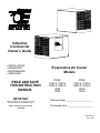
Industrial
Commercial
Owner’s Guide
• INSTALLATION
• OPERATION
• MAINTENANCE
• SERVICING
Evaporative Air Cooler
Models
PCRD PCRS
READ AND SAVE
THIS INSTRUCTION
MANUAL
11000 & 11000-2
13000 & 13000-2
15000
16000
11000 & 11000-2
13000 & 13000-2
15000
16000
IMPORTANT
Note any damage on the freight bill, as any
damage claim must be filed with carrier.
Motor, motor pulley and belt sold
separately
Date purchase: _____________________
Purchased from: ____________________
P/N 522319
Rev. 6/02

2
Evaporative Cooling
Evaporative cooling uses the principle of evaporation to lower the air temperature. Hot, dry air is passed through wetted
filters and is converted to refreshingly cooled air. Essick Coolers make the best use of the evaporative process by
controlling the flow of water, spreading the water evenly over the filters, and keeping a steady stream of cooled air
entering the building. It is exhausted out open windows or doors, carrying heat, smoke and odors along with it. Essick
evaporative coolers are 80% less costly to operate than refrigerated air conditioners.
INSTALLATION OF EVAPORATIVE COOLERS
PREPARATION
1. All electrical and duct work must comply with local and federal codes.
2. Make arrangements to get the cooler from ground to roof (crane, hoist, etc.).
LOCATION
1. Cooler should not be mounted near exhaust openings or vent pipes where fumes and odors can be drawn into cooler.
2. Ensure mounting surface is strong enough to support the cooler. Operating weight will be much heavier than shipping
weight.
3. Locate cooler so that fresh air is drawn in; air is not recirculated.
ROOF MOUNT UNITS
1. Select the location, taking into account roof construction and duct requirements. If rafters are cut when the roof
opening is cut, be sure to strengthen them.
2. Purchase or construct a platform to provide a level, mounting surface for the cooler. Always mount the cooler high
enough to allow easy access to the drain fitting.
3. Measure cooler or use the spec sheet to determine size of platform. Platform must be located so that the discharge
opening of the cooler is in line with the ductwork. On pitched roofs, the platform frame may be covered with galvanized
sheet steel or other weatherproof materials. Openings or removable panels must be left to allow access to the drain
fittings. On down discharge coolers the duct should be fastened to the platform collar before cooler is set in place.
The duct should have a standing flange for the cooler discharge opening to fit. Flash and seal the duct and roof
opening to provide weather tightness.
CAUTION: TO AVOID RISK OF FIRE, ELECTRICAL SHOCK, OR SERIOUS PERSONAL INJURY, BE SURE TO
DISCONNECT POWER FROM UNIT BEFORE CLEANING OR SERVICING.
WARNING: TO REDUCE THE RISK OF FIRE OR SHOCK; DO NOT USE THIS FAN WITH ANY SOLID STATE SPEED
CONTROL DEVICE.
DUCT WORK
1. The most important rule to follow when designing duct work is: AN EVAPORATIVE COOLER DEPENDS UPON A
LARGE VOLUME OF AIR COMING OUT OF THE DUCT WORK AT HIGH VELOCITY IN ORDER TO COOL
PROPERLY.
2. Do not “reduce” the discharge opening of the cooler.
3. Do not undersize the duct work and make it much smaller than the discharge opening. (In most cases, air conditioning
duct work is too small for coolers.)
4. Extra long ducts cause static pressure and will reduce airflow. They also pick up heat and
diminish the effect of the cooled air.
5. The motor pulley may be adjusted to compensate for ductwork.
6. Sharp or abrupt bends hinder airflow.
7. Poorly designed ceiling diffusers will ruin a successful installation. Install diffusers that are
designed for use with evaporative coolers.
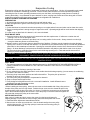
M
Before installing the motor pulley, loosen the set screw on the threaded side of the pulley and turn
that jaw of the pulley until it is fully closed. Position the set screw over the closest flat spot in the
thread and then open the jaw of the pulley 3 or 4 turns. Position the set screw over the closest flat
spot in the thread and retighten the set screw. Place the pulley on the motor shaft and tighten the
set screw that secures the pulley to the motor shaft.
OTOR PULLEY INSTALLATION
MOTOR INSTALLATION
After cooler is in place and level, remove the motor from the box and inspect for
shipping damage. Ensure that the motor voltage, phase and horsepower are correct.
1. Install the Motor Adjustment Assemblies as shown.
2. Mount motor on motor mount as shown. Use the slots that align the motor pulley
with the blower pulley. To fully align pulleys, loosen set screw securing pulley to
motor shaft and then align.

3
BELT ADJUSTMENT
An improperly adjusted belt will greatly shorten motor life. A deflection of 1” with 3 to 5
pounds of force applied will indicate proper adjustment. Do Not use the motor pulley to
adjust belt tension. Always use the Motor Adjustment Assemblies to adjust the belt
tension.
OVERFLOW PIPE INSTALLATION
Place the rubber washer onto the drain bushing. Slide the bushing through the drain
opening, in the cooler bottom, from the top side. Screw the nut onto the bushing from
under the cooler.
CAUTION: DO NOT HOOK THIS COOLER TO A WATER SOFTENER. THIS WILL
VOID THE WARRANTY.
Reservoir
WATER CONNECTION
The float valves are mounted in the cooler at the factory. To connect water to the unit,
run a ¼” copper water line into the front of the cooler through the hole provided.
Connect the water line to the compression T provided.
BLEEDOFF
In hard water areas, a bleed off kit may be installed to dispose of small amounts of
mineralized water allowing fresh water to replace it. Bleedoff kits are included with the
cooler. To install, cut the water tube about 6 inches from the pump discharge. Place
the tee in the line and connect the bleedoff line. Run the bleedoff line out through the
overflow assembly. Run the bleedoff tube to the nearest roof drain. DO NOT
DISPOSE OF BLEEDOFF WATER ONTO THE ROOF.
ELECTRICAL POWER
1. The installation of electrical wiring must conform to all local and federal codes and
should be done by a certified electrician.
2. Connecting the motor and/or pump to the wrong voltage will void the warranty.
Warning: To avoid risk of electrical shock, disconnect the power before opening or attempting service on this unit.
Notice to Installer: The motor amperage must be set as close as possible to motor nameplate amps without the pump
running.
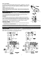
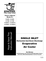
WIRING DIAGRAMS
Motor starter to be equipped with overload relay sized to accommodate motor full load amps.
Motor starters and overloads are not supplied with units.
PUMP
MOTOR
115V SUPPLY
GREEN
RED
3
PUMP
BLACK
STRIPED
BROWN
SINGLE SPEED
DIAGRAM
RED
3
1

4
START UP
After installing cooler and before filling with water:
1. Open windows and doors or other exhaust openings in building.
2. Turn on cooler and check amperage at the incoming white lead, using clamp on ammeter. If amperage reads above
motor name plate, refer to the motor pulley adjustment instructions (page 2) and open the pulley ½ turn. Restart cooler
and recheck amperage. If amperage reads below motor name plate, close the pulley ½ turn. Restart cooler and
recheck amperage.
3. Turn on water to cooler and ensure that connections do not leak.
4. Fill pan to ½” below top of overflow tube and ensure that the float cuts off water completely.
5. Switch the cooler to the cooling mode and check that water is flowing to the modules and that the pads are wetting
evenly.
MAINTENANCE
CAUTION: Turn off all electrical power to this unit before opening or attempting any
service.
Occasionally inspect your cooler for leaks, loose belt, blocked water lines, correct belt
alignment or excessive residue buildup on the pads. Inspect cabinet for rust. If rust
spots appear, sand and paint with a high-grade, corrosion resistant paint.
OILING
Lube the blower bearings twice per year. Use SAE 20W or 30W, non-detergent oil on
bearings with oil cups and standard bearing grease on ball bearings. Oil the blower
motor if it is equipped with oil holes. Some motors are permanently lubricated at the
factory.
REMOVING GRILLES
Slip a small screwdriver under a stainless steel clip and pry up until clip snaps open.
Repeat for other nine clips. Ensure that grille is set in a safe place where it can not
fall and/or will not be broken.
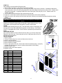
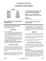
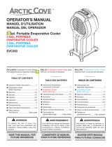
REPLACING MEDIA
1. Remove grilles.
2. Tilt top of module away from cooler and disconnect water hose.
3. Remove vertical retainers.
4. Remove polyester filter and discard.
5. Remove bottom of module.
6. Remove and replace CEL-dek. Ensure that Cel-dek is oriented properly. Improperly
oriented CEL-dek will cause cooler to entrain water and blow it into building.
7. Replace polyester filter.
8. Replace bottom and vertical supports.
9. Replace module.
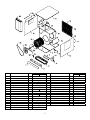
Item P/N Description
1 516142 Retainer-Vertical
2 504139 Top Support
3 523167 Channel
4 524298 Top
5 524178 Water Distributor
6 524295 Grommet
7 524101 CEL-dek
8 504138 CEL-dek
9 523176 Bottom
10 598895 Polyester Filter
11 587043 Screws
12 587003 Screws
13 588000 Tinnerman
14 524298 Rubber End Cap
15 504162 Tension Plate
16 589096 Pop Rivets
13
14
11
8
11
10
1
12
2
16
3
13
4
5
11
8
11
6
7
15
9
60°
30°
Proper Pad
Orientation
Air
Flow

8
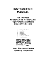
Part Number Part Number
Item Description Qty
PCRD PCRS
Item Description Qty
PCRD PCRS
1 Reservoir cover 2 514544 18 Blower housing 1 70708
2 Module support 2 504137 19 Blower wheel 1 70640
3 Reservoir 2 523110 20 Shaft 1 70672
4 Splash baffle 2 70722 21 Bearing 2 583005
5 Pump (115V) 2 506657 22 Set collar 2 501242
Pump (230V) 2 506658 23 Blower pulley 1 583095
6 Pump bracket 2 70547 24 Bearing angle 2 514699
7 Bottom assembly 1 70710 70715 25 Overflow assembly 2 515100
8 Float 2 524198 26 Belt 1 Sold separately
9 Float bracket 2 514697 27 Back panel 1 70712
10 Front panel 1 70713 70717 28 Module assembly 4 515193
11 Blower cutoff 1 70718 29 Drip strip 1 70724
12 Grille clip 20 30105 30 Access panel 1 70714
13 Grille 8 29931 31 Motor pulley 1 Sold separately
14 Grille assembly 2 515196 32 Motor adjustment assy 2 512221
15 Grille support 10 504143 33 Motor 1 Sold separately
16 Top assembly 1 70709
17 Motor mount 1 70686
5

6
Limited Warranty
This warranty is extended to the original purchaser only of an evaporative cooler installed and used under normal
conditions. It does not cover damages incurred during shipping or through accident, neglect, or abuse by the owner.
Essick Air Products does not authorize any person or representative to assume any other or different liability in connection
with this product.
Terms and conditions of warranty
This warranty includes lifetime limited coverage on water reservoir against any leakage due to defects in material. From
date of installation, if any original component part provided by Essick Air Products fails due to defect in material or factory
workmanship only, Essick Air Products will provide the replacement parts as follows:
Cabinet components for one year from date of installation
Evaporative media for two years from date of installation
Exclusions from this warranty
Essick Air Products is not responsible for incidental or consequential damage resulting from any malfunction.
Essick Air Products is not responsible for any damage occurring from the use of water softeners, chemicals, descale
material, or if a higher horsepower motor than what Essick Air Products recommends is used in the unit.
Essick Air Products is not responsible for the cost of service calls to diagnose cause of trouble, or labor charge to
repair and/or replace parts.
How to obtain service under this warranty
Contact the Dealer where you purchased the evaporative cooler. If for any reason you are not satisfied with the response
for the Dealer, contact Customer Service Department: Essick Air Products Inc. 5800 Murray Street, Little Rock, Arkansas
72209. 1-800-643-8341.
-
 1
1
-
 2
2
-
 3
3
-
 4
4
-
 5
5
-
 6
6


Ask a question and I''ll find the answer in the document
Finding information in a document is now easier with AI
Related papers
-
 Essick The Penguin PCRDS 8000 Owner's manual
-
 Essick N30G Owner's manual
-
 Essick E3400 Owner's manual
-
 Essick CD16 Owner's manual
-
 Essick SI-700S12 Owner's manual
-
Essick ECR 7200 User manual
-
Essick Excel RN46W Owner's manual
-
Essick Excel RN46W User manual
-
Essick N- Series User manual
-
 Essick N30S Owner's manual


Other documents
-
 Hessaire CP900 Installation guide
-
 Hessaire BRL Operating instructions
-
 DIAL 3453 Operating instructions
-
 Aspen Snow Cool BRL Installation guide
-
Aerocool 05-002-0251 Operating instructions
-
-
 Breezair MobileMAX III Owner's manual
-
-
 Arctic Cove EVC350 User guide
-
Champion 4000C RLD4 User manual


