Page is loading ...

Single Point Stereo
In-Ceiling Speaker
Installation Manual
Models #50-10580, 50-10581
Stellar Labs
Division of MCM Electronics
650 Congress Park Drive
Centerville, Ohio 45459
www.mcmelectronics.com
© 2010 MCM a Premier Farnell Company

General Features
• Isolated left and right channel capability from a single speaker
• Polypropylene cone woofer
• Butyl rubber surround
• Dual 3/4" soft dome tweeters
• Dual 12dB/octave crossovers
• Detachable screw terminal strips
• Installation in standard sheetrock ceilings without additional hardware
Specifications Model 50-10581 Model 50-10580
Woofer Size 6½" 8"
Power Capacity 35W/50W RMS/peak per channel 40W/60W RMS/peak per channel
Frequency Response 55Hz ~ 22KHz 50Hz ~ 22KHz
Nominal Impedance 8Ω per channel 8Ω per channel
SPL 87dB W/M 88dB W/M
Dimensions
Overall Frame Diameter 9.375" (dia.) 11.5" (dia.)
Required Cutout 8.10" (dia.) 10.0" (dia.)
Mounting Depth 5.25" 6"
Speaker Placement
Careful consideration should be made when determining the desired location of this speaker. As these are referred to as ceiling
speakers, this is the intended mounting location. However, there is no electronic or physical reason these cannot be mounted
in other locations. Note that careful consideration should be given to appearance in these situations.
Following are some typical guidelines that should be followed when determining the optimum placement for speakers in a given
environment. Note that these are guidelines. Aesthetics, light fixtures, ceiling fans and similar items will also require
consideration, and should be considered equally important to the recommendations below.
Unique Single Point Stereo™ Feature
This speaker incorporates a unique Single Point Stereo™ design, which allows it to be connected to both the left and right
channel of an amplifier, while retaining complete channel isolation. This is perfect when sound is desired in small areas, such as
entryways, small lavatories, hallways and similar areas, where location of two speakers may not be desirable. This speaker will
ensure that both the left and right channels are heard from a single point, without compromising left/right channel isolation in
other listening zones.
Whole House Audio Listening
Given a typical rectangular room, the ideal ceiling placement for these speakers is depicted below. When installing a single
speaker in a given room, the optimum placement is directly in the center. When installing a pair of speakers, bisect the room in
both the long and short dimensions. This will provide an exact center point. Then along the long length, bisect each half.
Where each of these bisected lines cross the center point, is the optimum speaker location.
Since these speakers are mounted in a 15° offset frame, it is also recommended that the location be shifted from the center
line displayed above. With an 8' ceiling, the shift is 8" from center. With a 10' ceiling, the shift is 14.5" from center, and with a
12' ceiling, the shift is 19" from the center line of the ceiling.
It is important to note that more speakers in a given listening area do not necessarily equate to higher sound levels. With more
speakers, the desired listening level for a given area is attained with lower output from each speaker. This creates a much
more pleasant listening environment as the sound source can be uniformly heard through the entire room, regardless of
location and with less interference with sounds such as conversation.

Speaker Wire
It is important that good quality wire is used in the installation. Installed speakers generally have much longer wire runs than
normal home theater speakers, hence heavier gauge wire is recommended. Note: There are numerous manufactures in the
market offering “high-end” esoteric speaker wire, with claims of exotic materials and superior performance. Truthfully, this
type of product has been found to provide little or no benefit to installations of this type. Good quality 16AWG CL2 rated in-
wall wire, such as MCM #24-9995 (two-conductor), #24-10015 (four-conductor) or similar, provide outstanding performance in
this application.
When running this cable, a few simple guidelines must be followed
• All speakers should be home-run. That is, wire should be run directly from each speaker, back to the sound source
• Speaker wire should be kept away from AC wiring to prevent noise. If AC wiring and speaker wire must cross
paths, it is best to have them cross at a 90º angle, minimizing the common surface area between the two
• Speaker wire and AC lines should NEVER pass through the same hole in studs or joists
Installation
1. For this type is installation, a stud finder such as MCM #2210880 is highly recommended. This device will not only
accurately locates both edges of the stud, but will provide a warning of nearby electrical wiring.
2. When deciding on a final location to install speakers, extreme care should be taken to ensure that obstructions do
not exist, such as air ducts, plumbing and electrical wiring.
3. Locate the studs in the wall between which the speaker will be mounted. Using a pencil, mark a spot directly in
the center of the two studs
4. Locate the cardboard mounting template, included with the speaker, and using a tape measure, determine its
exact center point.
5. Poke a small hole in the template, and place the template on the wall, lining up the hole with the spot marked on
the ceiling. Using a level, make sure the template is level and plumb on the wall.
6. Trace the outer perimeter of the template with a pencil.
7. Using a wallboard saw, similar to MCM #22-7597, cut around this circumference. This type of saw is especially
useful, as its rigid design and sharp point allow it to “plunge” into the wall with no need to drill a pilot hole.
8. Remove the rectangular section of drywall from the wall.
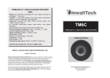
9. Remove the front grille from the speaker to be installed. This is most easily accomplished by rotating the plastic
mounting clips outward, and pressing then towards the front speaker frame. This will cause the screw heads, behind
the grill, to push the grill out from inside. In some cases, it may be necessary to gently pry the grill from the front.
This may be done with a small knife blade or micro size flat blade screwdriver. In this case, extreme care should be
taken not to damage the plastic frame around the grill.
10. When looking at the rear of the speaker, rotate the four mounting clips clockwise as far as they well go, so as not
to obstruct the frame. If necessary, loosen the four mounting screws, from the front of the speaker, to allow these
clips to rotate freely within their bracket.
11. Locate the green terminal strip on the rear of the speaker, connections marked ( – ) and ( + ). This is a two-part
terminal strip, with the screw terminals being detachable from the PC board. Unplug the screw-connector portion of
the strip, allowing easy access to the screws. Strip ¼" of insulation from the end of the speaker wire, insert into the
terminal strip, and tighten the screws. Take care to observe correct polarity. Then plug the terminal strip back into
the PC board on the rear of the speaker.
12. Fully insert the speaker into the wall opening and begin to tighten the four mounting screws. Care should be
taken when tightening these screws. Make sure the screwdriver is secure in the head of the screw and does not slip
out and damage the speaker cone.
13. As screws are tightened, the plastic mounting clips will rotate clockwise and draw in against the inside of the
wallboard. If using a drill to tighten screws, tighten all four until the speaker frame just makes contact with the
ceiling. From there, it is best to use a hand screwdriver to fully tighten. This will prevent breakage of the plastic
mounting clips.
14. Once all screws are tightened, the grill may be reinstalled on the front of the speaker.
15. The other end of the speaker wire is now ready for connection to the sound source

Warranty
MCM Custom Audio and Stellar Labs products are warranted, by MCM Electronics, against
manufacturer defects for a period of two years from the original date of purchase. This warranty is
limited to manufacturer defects, in either materials or workmanship. MCM Electronics, or any other
worldwide divisions of Premier Farnell PLC, are not responsible for any consequential or
inconsequential damage to any other component, structure or the cost of installation or removal of
said items.
This warranty will not cover damage due to improper use such as (and not limited to) damaged
cones, mounting frames, voice coils or items damaged by whether damaged items.
For questions or specific information regarding warranty replacement or repair, contact:
MCM Electronics
www.mcmelectronics.com
800-543-4330
/