Brink Renovent Excellent 450 Installation guide

Type
Installation guide
Renovent Excellent 450 (Plus)
WWW.BRINKAIRFORLIFE.NL 614784-E
INSTALLATION INSTRUCTIONS (English)
Heat recovery appliance
Renovent Excellent 450 (Plus)
STORE NEAR THE APPLIANCE
Installation instructions
This appliance can be used by children aged from 8 years and above and persons with reduced
physical, sensory or mental capabilities or lack of experience and knowledge if they have been given
supervision or instruction concerning use of the appliance in a safe way and understand the hazards
involved.
Children shall not play with the appliance.
Cleaning and user maintenance shall not be made by children without supervision.
GB
Renovent Excellent 450 Rev. E
1
1.1
1.2
2
3
3.1
3.2
3.2.1
3.2.24
3.3
4
4.1
4.2
4.3
4.4
5
5.1
5.2
5.3
5.4
5.5
5.5.1
5.5.2
5.5.3
6
6.1
6.2
6.2.1
6.2.2
6.2.3
6.3
6.4
6.5
7
7.1
7.2
7.3
7.4
8
8.1
8.2
Delivery..........................................................
Scope of delivery ............................................
Accessories Renovent Excellent ....................
Application ....................................................
Version...........................................................
Technical information ......................................
Connections and dimensions .........................
Renovent Excellent right-handed version .......
Renovent Excellent left-handed version .........
Exploded view appliance ................................
Operation .......................................................
Description......................................................
Bypass conditions...........................................
Frost safety .....................................................
Renovent Excellent Plus.................................
Installation .....................................................
Installation general .........................................
Placing the appliance .....................................
Connecting the condensate discharge ...........
Connecting ducts ............................................
Electric connections........................................
Connection of the power plug .........................
Connecting the multiple switch .......................
Connection eBus ............................................
Display ...........................................................
General explanation control panel ..................
Operating mode ..............................................
Status system fan ...........................................
'LVSOD\DLUÀRZUDWH ........................................
Message text for operating mode ...................
Settings menu.................................................
Readout menu ................................................
Service menu..................................................
Putting into operation ..................................
6ZLWFKLQJWKHDSSOLDQFHRQDQGRႇ .................
Setting the air quantity ....................................
Other settings installer ....................................
Factory setting ................................................
Fault ...............................................................
Trouble shooting .............................................
Display codes .................................................
1
1
2
5
6
6
7
7
7
8
9
9
9
9
9
10
10
10
10
10
12
12
12
12
13
13
14
14
14
15
16
17
18
19
19
20
20
20
21
21
21
Table of contents
9
9.1
9.2
10
10.1
11
11.1
11.2
11.2.1
11.2.2
11.2.3
11.2.4
11.3
11.4
11.5
11.6
11.7
11.8
12
12.1
12.2
13
14
Maintenance ................................................
Filter cleaning ..............................................
Maintenance .................................................
Electric diagrams........................................
Basic diagram ...............................................
Electric connections accessories .............
Connections connectors ...............................
Connection examples multiple switch...........
0XOWLSOHVZLWFKZLWK¿OWHULQGLFDWLRQ ...............
:LUHOHVVUHPRWHFRQWUROZLWKRXW¿OWHULQGLFD-
tion)...............................................................
$GGLWLRQDO PXOWLSOH VZLWFK ZLWK ¿OWHU LQGLFD-
tion ................................................................
Additional multiple switch wireless remote
control ...........................................................
Coupling through eBus; all appliances equal
DLUÀRZUDWH ...................................................
Connecting RH(huminity)-sensor .................
Wiring diagram postheater connection (only
for Renovent Excellent Plus) ........................
Connection example geo heat exchanger
(only possible for the Renovent Excellent
Plus) .............................................................
Connecting external switch contact (only
possible for Renovent Excellent Plus) ..........
Connection to 0-10 V input (only possible for
Renovent Excellent Plus) .............................
Service .........................................................
Exploded view ..............................................
Service articles .............................................
Setting values .............................................
Declaration of conformity ..............................
ErP-values ....................................................
23
23
24
26
26
27
27
28
28
28
28
28
29
29
30
31
32
33
34
34
34
36
39
40
Renovent Excellent 450 Rev. E
Chapter 1 Delivery
Before starting installation of the heat recovery unit, check that it has been supplied complete and undamaged.
The scope of delivery of the heat recovery unit Renovent Excellent includes the following components:
c Heat recovery appliance type Renovent Excellent
d Wall mounting bracket kit containing:
   [VXVSHQVLRQVWULSV
   [SURWHFWLYHFDSV
   [UXEEHUVWULS
   [UXEEHUULQJV
   [PRXQWLQJLQVWUXFWLRQV
e PVC condensate discharge connection containing:
   [V\QWKHWLFVFUHZJODQG´
   [VHDOLQJULQJ
   [39&JOXHGFRXSOLQJPP
f Documentation set consisting:
   [VKRUWPDQXDO
1.1 Scope of delivery
1
2
34
2 Renovent Excellent 450 Rev. E
Chapter 1 Delivery
1.2 Accessories Renovent Excellent
Article description Article
code
Splitter RJ12 510472
Ebus CO
2
-sensor (only possible for Renovent Excellent Plus)532126
Transmitter wireless remote control 2 positions (with. battery) 532170
Transmitter wireless remote control 4 positions (with. battery) 532171
Receiver wireless remote control (for battery version) 532172
Kit wireless remote control 2 positions (1 transmitter & 1 receiver) 532173
Kit wireless remote control 4 positions (1 transmitter & 1 receiver) 532174
ZD\VZLWFKZKLWHÀXVKPRXQWHGZLWKRXW¿OWHULQGLFDWLRQ
Delivered with insert plate and cover frame 540214
ZD\VZLWFKZLWK¿OWHULQGLFDWLRQÀXVKPRXQWHGPRGXODUFRQQHFWLRQ
Delivered with insert plate and cover frame 540262
Brink Air Control 510498
Electric postheater Excellent 450 Ø 180mm 310650
Electric (extra) preheater Excellent 450 Ø 180mm 310660
Renovent Excellent 450 Rev. E 3
Chapter 1 Delivery
Article description Article code
)LOWHUNLW[,62H30)¿OWHUSFV 531771
Filterset 1x ISO Coarse 45% (G3) &
1x ISO ePM 1 50% (F7) (2 stuks) 531773
RH-sensor 310657
Mounting support Excellent 450 217035
Enthalpie heat exchanger 532059
Servicetool 531961
4 Renovent Excellent 450 Rev. E
Renovent Excellent 450 Rev. E
The Brink Renovent Excellent is a ventilation unit with heat re-
FRYHU\ZLWKDQKLJKHႈFLHQF\DPD[LPXPYHQWLODWLRQFDSDFLW\
of 450 m
3
/h and low-energy fans.
Features Renovent Excellent 450:
 VWHSOHVVO\DGMXVWDEOHDLUÀRZUDWHVWKURXJKDFRQWUROSDQHO
 ¿OWHULQGLFDWLRQRQWKHDSSOLDQFHDQGWKHSRVVLELOLW\IRU¿OWHU
indication on the multiple switch;
 D FRPSOHWHO\ QHZ LQWHOOLJHQW IURVW SURWHFWLRQ V\VWHP ZKLFK
ensures that also at low outdoor temperatures the appli-
ance's performance remains optimal and that, if necessary,
it activates the standard preheater.
 ORZVRXQGOHYHO
 FRPHVDVVWDQGDUGZLWKDXWRPDWLFE\SDVVYDOYH
 FRQVWDQWÀRZFRQWURO
 ORZHQHUJ\FRQVXPSWLRQ
 KLJKHႈFLHQF\
Renovent Excellent 450 is available in two types:
 5HQRYHQW([FHOOHQW´
 5HQRYHQW([FHOOHQW3OXV´
Compared to the Renovent Excellent, the Renovent Excellent
Plus has a more extensive control board which increases the
connection options.
These installation instruction describe both the standard Reno-
vent Excellent and the Renovent Excellent Plus.
The Renovent Excellent (Plus) is available in the left-handed
RU ULJKWKDQGHG YHUVLRQ$ OHIWKDQGHG YHUVLRQ KDV WKH ¿OWHUV
RQWKHOHIWEHKLQGWKH¿OWHUGRRUDULJKWKDQGHGYHUVLRQKDVWKH
¿OWHUVRQWKHULJKWEHKLQGWKH¿OWHUHGGRRU7KHSRVLWLRQRIWKH
DLUGXFWVGLႇHUVIRUWKHVHWZRYHUVLRQV)RUWKHFRUUHFWSRVLWLRQ
of the connection ducts and dimensions see §3.2.
The Renovent Excellent comes ready to plug in with a 230 V
mains plug and a connection for a low-voltage multiple switch
on the outside of the appliance.
Version types Renovent Excellent 450
Type Version L of R Position air ducts Power supply Type code Brink code
Renovent Excellent
Left-handed version 4 top connections Power plug 4/0 L 421200
Right-hand version 4 top connections Power plug 4/0 R 420200
Renovent Excellent Plus
Left-handed version 4 top connections Power plug 4/0 L+ 421201
Right-hand version 4 top connections Power plug 4/0 R+ 420201
Chapter 2 Application
6 Renovent Excellent 450 Rev. E
Chapter 3 Version
3.1 Technical information
Sound power Excellent 450
Ventilation capacity [m
3
/h] 100 200 225 300 400
Sound power
level Lw (A)
Static pressure [Pa] 9 40 38 80 47 100 84 175 240 150 225
Housing emission [dB(A) 29.5 32.5 40.5 40.5 43.5 47.5 51.0 53.0 54.0 54.5 57.0
'XFW³IURPGZHOOLQJ´>G%$@ 31.5 34.5 46.5 48.0 48.5 50.0 56.5 57.0 58.0 59.0 60.0
'XFW³WRGZHOOLQJ´>G%$@ 42.5 47.5 57.0 59.0 60.5 62.5 66.0 68.5 69.5 70.5 71.5
In practice, the value may deviate 1 dB(A) as a result of measuring tolerances
Renovent Excellent 450
Supply voltage [V/Hz] 230/50
Protection degree IP30
Dimensions (w x h x d) [mm] 677 x 765 x 564
Duct diameter [mm] Ø180
External diameter condensate discharge [mm] Ø32
Weight [kg] 38
Filter class ISO Coarse 45% (G3) (ISO ePM 1 50% (F7) optional for supply)
Fan setting (factory setting)) 1 2 3
Ventilation capacity [m
3
/h] 50 100 200 300
Permissible resistance ducts system [Pa] 2 - 5 5 - 15 20 - 60 40 - 130
Rated power (excl. preheater)[W] 9,5 11 - 18 32 - 45 80 - 105
Rated current (excl. preheater)[A] 0,10 0,10 - 0,18 0,30 - 0,46 0,70 - 0,95
Max. rated current (with preheater switched on) [A] 6
&RVij 0,43 0,43 - 0,45 0,43 - 0,45 0,48 - 0,50
Flow rate [m
3
/h]
Resistance ducts system [Pa]
Fan graph Renovent Excellent 450
0
50
100
150
200
250
300
350
400
0 25 50 75 100 125 150 175 200 225 250 275 300 325 350 375 400 425 450 475
111
123
123
111
6 8
95
81
13
12
11
21
18
16
32
30
25
52
45
40
75
65
57
Note: The value stated in the
circle is the capacity per fan (in
Watt)
Renovent Excellent 450 Rev. E 7
Chapter 3 Version
3.2 Connections and dimensions Renovent Excellent 450
Renovent Excellent 450 Right-handed 4/0
1 = To dwelling
2 = To atmosphere
3 = From dwelling
4 = From atmosphere
5 = Electric connections
6 = Connection condensate discharge
7 = Wall mounting bracket (note the correct
position of the rubber strip, washers and caps)
Renovent Excellent 450 left-handed 4/0
Mounting wall suspension kit
7
10 mm
8 Renovent Excellent 450 Rev. E
Chapter 3 Version
1 Service connector Computer connection for service purposes.
2 Display and 4 control buttons Interface between user and control electronics.
3 Control board Contains the control electronics for the basic functions.
4([WUDFWDLU¿OWHU )LOWHUVDLUÀRZIURPGZHOOLQJ
5 Preheater Heats up the outdoor air when there is a risk of freezing for the heat exchanger
6 Heat exchanger Ensures heat transfer between input and output air
76XSSO\DLU¿OWHU Filters outdoor are supplied to the dwelling
8 Bypass valve Sends the air through or around the heat exchanger (For the 4/0 this
valve is in the upper part of the appliance)
9 Outdoor temperature sensor Measures outside air temperature.
10 Indoor temperature sensor Measures the dwelling air temperature
11 Condensate discharge Connection condensate discharge (Kit comes separately with the appliance)
12 Extract fan Discharges air from the dwelling to the atmosphere.
13 Supply fan Feeds fresh air into the dwelling.
14 Modular connector multiple switch X2 &RQQHFWLRQVIRUFDEOHWRPXOWLSOHVZLWFKLIGHVLUHGZLWK¿OWHULQGLFDWRU
15 Connector eBus X1 Connection for eBus control
16 Connector X15 Contains the various control inputs and outputs; only for Plus version
17 Connector X14 &RQQHFWLRQSRVWKHDWHURQO\IRU3OXVYHUVLRQDFFHVVLEOHDIWHUWDNLQJRႇWKH
display cover)
18 Mains cable 230 V Gland power cable 230 volt
19 Connection to postheater Gland 230 V cable to postheateror extra preheater; only for Plus version
Rear view display cover
(Plus version)
3.3 Exploded view appliance
123
4
5
6
7
9
10
8
11
12
13
19 18 17
14 15 16
Renovent Excellent 450 Rev. E
Chapter 4 Operation
4.2 Bypass conditions
The standard bypass valve makes it possible to supply fresh
outside air that is not heated by the heat exchanger. Particu-
larly during summer nights it is desirable to supply cooler out-
side air.
Then the hot air in the dwelling is replaced by cooler outside air
in so far as possible.
The bypass valve opens and closes automatically when a num-
EHURIFRQGLWLRQVDUHVDWLV¿HGUHIHUWRWKHWDEOHEHORZIRUE\-
pass conditions).
7KHRSHUDWLRQRIWKHE\SDVVYDOYHFDQEHDGMXVWHGLQVWHSQXP-
ber 5, 6 and step number 7 in the settings menu (see chapter
13).
4.3 Frost protection
To prevent freezing of the heat exchanger at extremely low out-
door temperatures, the Renovent Excellent features intelligent
frost control. Temperature sensors measure the temperatures
across the heat exchanger and, if necessary, the preheater is
switched on. That guarantees a proper ventilation balance,
also at very low outdoor temperatures. If, with switched on
preheater, the exchanger temperature still starts to drop below
zero, stepless unbalance is created in the appliance.
Bypass valve conditions
Bypass valve open - The outdoor temperature is higher than 7°C and
- the outdoor temperature is lower than the indoor temperature in the dwelling and
- the temperature in the dwelling is higher than the temperature set at step no. 5 in the set-
tings menu (set standard at 24°C).
Bypass valve closed - The outdoor temperature is lower than 7°C or
- the outdoor temperature is higher than de indoor temperature in the dwelling or
- the temperature outside the dwelling is lower than the temperature set at step no. 5 in the
settings menu minus the set temperature on the hysteresis (step no 6), this temperature is
standard set at 22 ° C (24.0 ° C minus 2.0 ° C).
4.4 Renovent Excellent Plus version
The Renovent Excellent is also available as Plus version. This
YHUVLRQLVHTXLSSHGZLWKDGLႇHUHQWFRQWUROERDUGZLWKDGGL-
tional connectors (X14 & X15) with more connection options for
various applications.
The 9-pole connector X15 is accessible at the rear of the Reno-
vent Excellent display cover without having to open the appli-
ance.
7KH SROH FRQQHFWRU ; LV DFFHVVLEOH DIWHU WDNLQJ Rႇ WKH
GLVSOD\ FRYHU 7KH GLVSOD\ FRYHU RI WKH ³3OXV´ YHUVLRQ KDV D
second gland. That makes it possible to feed a 230 volt cable,
which may be connected to connector X14, two outside the
appliance.
See § 11.1 for more information on the connection possibilities
of connectors X14 and X15.
4.1 Description
The appliance comes plug and play and operates fully auto-
matically. The extracted indoor air heats up the fresh, clean
outdoor air. That saves energy and fresh air is sent to the re-
quired rooms.
The control system has four ventilation modes. Dependent on
the connected multiple switch, 3 or 4 ventilation modes can be
XVHG7KHDLUÀRZUDWHFDQEHDGMXVWHGSHUYHQWLODWLRQPRGH
7KHFRQVWDQWYROXPHFRQWUROV\VWHPHQVXUHVWKDWWKHDLUÀRZ
rate of the supply and extract fans is realised independent of
the duct pressure.
X14
X15
10 Renovent Excellent 450 Rev. E
Chapter 5 Installation
5.1 Installation general
Installing the appliance
1. Placing the appliance (§5.2)
2. Connecting the condensate discharge (§5.3)
3. Connecting the ducts (§5.4)
4. Electric connection (§5.5)
Installation must take place under:
 4XDOLW\UHTXLUHPHQWVYHQWLODWLRQV\VWHPVGZHOOLQJV
 4XDOLW\UHTXLUHPHQWVEDODQFHGYHQWLODWLRQLQGZHOOLQJV
 7KH UHJXODWLRQV IRU YHQWLODWLRQ RI GZHOOLQJV DQG UHVLGHQWLDO
buildings.
 7KHVDIHW\UHJXODWLRQVIRUORZYROWDJHLQVWDOODWLRQV
 7KH UHJXODWLRQV IRU FRQQHFWLRQ WR LQWHULRU VHZHUV LQ GZHOO-
ings and residential buildings.
 $Q\DGGLWLRQDOUHJXODWLRQVRIWKHORFDOXWLOLWLHV
 7KHLQVWDOODWLRQLQVWUXFWLRQVIRUWKH5HQRYHQW([FHOOHQW
 ,QDGGLWLRQWRWKHDERYHGHVLJQDQGLQVWDOODWLRQUHTXLUHPHQWV
and recommendations, the national building and ventilation
regulations must be complied with.
5.2 Placing the appliance
The Renovent Excellent can directly be mounted to the wall
using the suspension brackets supplied for that purpose. For a
vibration-free result the appliance must be mounted to a solid
wall with a minimum mass of 200 kg/m
2
or on a base with at
least the same mass on a mounting support. A gypsum block
RUPHWDOVWXGZDOOGRHVQRWVXႈFH$GGLWLRQDOPHDVXUHVVXFK
as double panelling or extra studs are required in that case.
2QUHTXHVWDPRXQWLQJVXSSRUWIRUÀRRUPRXQWLQJLVDYDLODEOH
In addition, the following aspects must be taken into account.
 7KH KHDW UHFRYHU\ XQLW PXVW EH LQVWDOOHG LQ DQ LQVXODWHG
frost-free room to prevent, among other things, freezing of
the condensate discharge.
 7KHDSSOLDQFHPXVWEHSODFHGOHYHO
 ,WLVQRWSHUPLWWHGWRLQVWDOOWKHKHDWUHFRYHU\XQLWLQURRPV
with a high relative humidity (such as a bathroom).
 7KHLQVWDOODWLRQURRPPXVWEHVXFKWKDWDJRRGFRQGHQVD-
te discharge with air trap and pitch for condensate can be
made.
 7KHLQVWDOODWLRQURRPPXVWEHYHQWLODWHG
(That will prevent condensation on the outside of the heat
recovery unit.)
 0DNHVXUHWKHUHLVDIUHHVSDFHRIDWOHDVWFPDWWKHIURQW
of the appliance and a free headroom of 1.8 m for cleaning
WKH¿OWHUVDQGFDUU\LQJRXWPDLQWHQDQFH
 0DNHVXUHWKHUHLVDIUHHVSDFHRIDWOHDVWFPDERYHWKH
display cover so it can always be removed.
5.4 Connecting ducts
The air ducts must be mounted air-tight.
7KHDLU H[WUDFWGXFW GRHVQRW KDYHWR EH¿WWHG ZLWK D FRQWURO
YDOYH7KHDSSOLDQFHLWVHOIFRQWUROVWKHDLUÀRZUDWHV
A duct diameter of 180 mm is required for the Renovent Excel-
lent 450.
To prevent condensation on the outside of the outdoor air
supply duct and the air exhaust duct downstream of the
Renovent Excellent, these ducts must be provided with an
external vapour barrier as far as the appliance. If thermally
insulated piping is used here, additional insulation is not
necessary.
For compliance with the maximum installation noise level
of 30 dB, it will have to be assessed for every installation
VSHFL¿FDOO\ ZKDW PHDVXUHV ZLOO EH UHTXLUHG WR OLPLW WKH
noise.
$WOHDVWDPXႉHUZLWKDOHQJWKRIQRWOHVVWKDQPLVUH-
TXLUHGEXWDGGLWLRQDOPHDVXUHVPD\EHQHFHVVDU\3OHDVH
contact the Brink Consultancy Department if you have any
TXHVWLRQVRQWKLVVXEMHFW
Pay attention to crosstalk and installation noise, also for incor-
porated ducts. Design the duct with separate branches to the
valves to prevent crosstalk. If necessary, the supply ducts must
be insulated, for instance when they are installed outside the
insulated envelope. Preferably use Brink incorporated ducts.
These ducts have been developed with a view to a low duct
resistance.
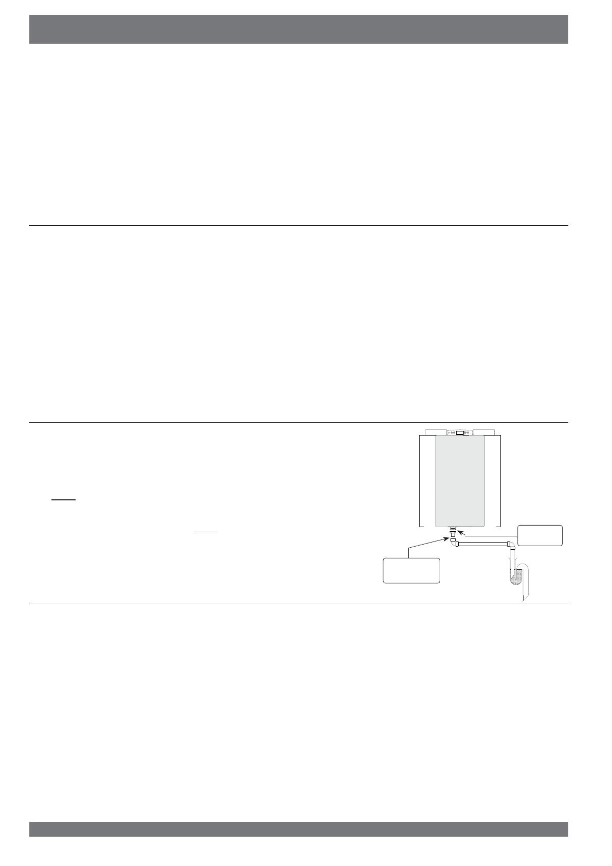
5.3 Connecting the condensate discharge
The condensate discharge line for the Brink Renovent HR is fed through the lower
panel. The condensate must be discharged through a drainpipe.
The condensate discharge comes separately with the appliance and the installer
must screw it into the underside of the appliance. This condensate discharge con-
nection has an external connecting diameter of 32 mm.
The condensate discharge line can be glued to it, if necessary using a square
bend. The installer can glue the condensate discharge in the desired position in
the lower part of the appliance. The drain must discharge under the water level in
the U-trap.
Before connecting the condensate discharge to the appliance, pour water into the
U-trap to create an air trap.
Screw
connection
Glued connec-
tion; Ø32 mm
Renovent Excellent 450 Rev. E 11
1
2
3
4a
4b
5
6
7
9
9
10 8
Chapter 5 Installation
 $UUDQJHWKHH[WHULRUDLUVXSSO\ IURP WKHVKDGRZHGVLGHRI
the dwelling, preferably from the wall or overhang. If the out-
door air is sucked in from under the tiles, it must be ensured
that no condensation develops in the roof boarding and no
water can run in. Ventilation air can be sucked in from under
the tiles if air can access freely at the top and the bottom of
the roof area and the sewage vent stack does not end under
the tiles.
 )HHGWKH H[WUDFWGXFW WKURXJK WKHURRI ERDUGLQJLQ VXFK D
manner that no condensation develops in the roof boarding.
 ,QVWDOOWKHH[WUDFWGXFWEHWZHHQWKH5HQRYHQW([FHOOHQWDQG
the roof sleeve in such a manner that surface condensation
is prevented.
 0RXQWLQJRIDLU GXFWVWR WKHURRI GHFN PXVWEH DYRLGHGLQ
order to prevent sound transmission
 $OZD\VXVHDQLQVXODWHGYHQWLODWLRQURRIVOHHYH
 ,WLVUHFRPPHQGHGWRUHVWULFWWKHH[WHUQDOGXFWSUHVVXUHLQ
WKHGHVLJQ WR 3D DWWKH GHVLJQÀRZ UDWH LQRUGHU OLPLW
the total sound level. In all events the practical external duct
pressure must be limited to 150 Pa If the resistance of the
duct system is higher, the maximum ventilation capacity will
be lower.
 7KHDLUYHORFLW\PXVWEHOLPLWHGWRPVLQWKHPDLQGXFWV
and 3,5 m/s in the branches
 7KH ORFDWLRQ RI WKH PHFKDQLFDO YHQWLODWLRQ RXWSXW DQG WKH
sewer stack vent relative must be chosen to prevent nui-
sance.
 &KRRVHWKHORFDWLRQRIWKHVXSSO\YDOYHVWRSUHYHQWIRXOLQJ
and draught. We recommend to use the Brink supply valves.
 :KHQPRXQWLQJÀH[LEOHGXFWVEHDULQPLQGWKDWLWPXVWEH
possible to replace them in due course.
 :KHQPRXQWLQJÀH[LEOHGXFWVEHDULQPLQGWKDWLWPXVWEH
possible to replace them in due course.
 $YRLGWKHXVHRISHWUROHXPEDVHGDGKHVLYHVLQDLUSODQWV\V-
tems.
 'ZHOOLQJVZLWKFRQVWUXFWLRQPRLVWXUHPXVWEHYHQWLODWHGQDW-
XUDOO\GXULQJDFHUWDLQSHULRG
,QVWDOOVXႈFLHQWRYHUÀRZRSHQLQJVGRRUJDSFP
1 = Renovent Excellent 450 left-handed 4/0 (place level)
2 = Preferred ventilation air supply
3 = Ventilation air supply under the tiles
4a = Free suction bottom roof area
4b = Free suction top roof area
5 = Sewer vent
6 = Preferred location extract ventilation air; use Brink insu-
lated ventilation roof sleeve.
7 = Thermally isolated pipe
8 = Condensate discharge
= 0uer
10 = Ducts from and to dwelling
²
²
A
A
BX
²
²
²
²
A
²
²
A t 60 mm
B t A
12
34
1 = Brink supply valves
2 = Supply from wall
3 = Suction valve in
ceiling or high in wall
4 = Prevent crosstalk
5 = Preferably Brink
incorporated ducts
a = Gap under the door
2 cm.
A = Spacing 10 mm above roof
deck
B = Roof insulation
C = Seal with foam
D = Pipe for make-up air to be
carefully insulated and pro-
vided with vapour barrier
12 Renovent Excellent 450 Rev. E
Chapter 5 Installation
5.5 Electric connections
5.5.2 Connecting the multiple switch
The multiple switch (not supplied with the appliance) is con-
nected to the modular connector type RJ12 (connector X2) that
is placed at the rear of the appliance's display cover.
Dependent on the type of multiple switch that is used, a plug
RJ11 or RJ12 can be connected to it.
 $SSOLFDWLRQ RI D ZD\ VZLWFK ZLWK ¿OWHU LQGLFDWLRQ LQ DOO
cases requires an RJ12 plug in combination with a 6-core
modular cable.
 $SSOLFDWLRQRIDZD\VZLWFKZLWKRXW¿OWHULQGLFDWLRQLQDOO
cases requires an RJ11 plug in combination with a 4-core
modular cable.
Refer to diagrams §11.2.1 to §11.2.4 for connection examples
multiple switch.
Other options include wireless remote control or a combination
of multiple switches.
The 4-way switch can also be used to activate a 30-minutes
boost mode by putting the switch to setting 3 for less than 2
seconds and directly turning it back to setting 1 or 2. The boost
mode can be reset by putting the switch to setting 3 for longer
than 2 seconds or by switching it to absence mode ( ).
5.5.1 Connecting the power plug
The appliance can be connected to an easily accessible,
earthed wall socket with the plug that is mounted to the ap-
pliance. The electric installation must comply with the require-
ments of your power company.
Make allowance for the 1000 W preheater.
Warning
The fans and control board carry a high volt-
age. Always take the voltage from the appli-
ance by pulling the power plug when working
on the appliance.
5.5.3 Connecting eBus
The Renovent Excellent operate with eBus protocol. The set-
ting of parameter 08 in the settings menu (see chapter 13) lets
you choose between eBus and OpenTherm.
An eBus connection can be made with the 2-pole connector X1
at the rear of the display cover.
The eBus protocol can for instance be used for coupling (cas-
cade control) appliances (see §11.3). Because of polarity sen-
sitivity, always connect contacts X1-1 to X1-1 and contacts
X1-2 to X1-2 ; the appliance will not work when these contacts
DUHLQWHUFKDQJHG
RJ12
X1
A
A Cables to be connected by installer
(minimum wire diameter 0.34 mm
2
)
The optionally available control unit must be connec-
ted to this connector eBUS.
nr.1
nr.2
X1
Renovent Excellent 450 Rev. E
6.1 General explanation control panel
The LCD display shows what the operating situation of the ap-
pliance is.
Four control keys can be used to call up and modify
settings in the control unit program.
When the mains power to the Renovent Excellent is switched on,
all display symbols will appear during 2 seconds; at the same time
the blue backlight is switched on for 60 seconds.
When one of the control keys is operated, the display will light
up during 30 seconds.
When no keys are operated or when no deviating situation has
developed (such as a blocking fault) the display will show the
operating mode (see § 6.2).
$IWHURSHUDWLQJWKHNH\µ0HQX¶WKHNH\V³´RU³´FDQEHXVHG
WRVHOHFWIURPWKUHHGLႇHUHQWPHQXVLQFOXGLQJ
 Settings menu (SET); see § 6.3
 Readout menu (READ), see § 6.4
 Service menu (SERV), see § 6.5
Press the R key to leave any menu and return to operating
mode.
%ULHÀ\SUHVVWKH5NH\VKRUWHUWKDQVHFRQGVWRVZLWFKRQ
the display backlight without changing anything in the menu.
Key Function key
Menu $FWLYDWHWKHVHWWLQJVPHQXWRWKHQH[WVWHSLQWKHVXEPHQXFRQ¿UPYDOXHFKDQJH
-6FUROOPRGLI\YDOXH6ZLWFKLQJRQRURႇWKH5HQRYHQW([FHOOHQWIURPRSHUDWLQJPRGHWKHSUHVVIRUVHFRQGV
+ Scroll; modify value
R2QHVWHSEDFNLQPHQXFDQFHOYDOXHPRGL¿FDWLRQ¿OWHUUHVHWWKHSUHVVIRUVHFRQGVGHOHWHIDXOWKLVWRU\
Chapter 6 Display image
A = LCD
B = 4 control keys
C = service connector
.
A
B
C
14 Renovent Excellent 450 Rev. E
6.2 Operating mode
In operating mode the display may simultaneously show 4 dif-
ferent situations/values.
1 = Status fan situation, image coupled appliances (see
§ 6.2.1)
 $LUÀRZUDWH (see § 6.2.2)
3 = Message textHJWH[W¿OWHUVLWXDWLRQDFWLYDWLRQH[WHU-
nal switch contact etc. (see § 6.2.3)
4 = Fault symbol (see § 8.1 and § 8.2)
7KLVVKRZVWKHVHWDLUÀRZUDWHRIWKHVXSSO\RIH[WUDFWIDQ
:KHQZKHQWKHDLUÀRZUDWHVRIWKHVXSSO\DQGH[WUDFWIDQV
GLႇHUIRULQVWDQFHZKHQXVLQJDQH[WHUQDOVZLWFKFRQWDFWLQ
DOOFDVHVWKHKLJKHVWDLUÀRZUDWHLVVKRZQ
:KHQWKH DSSOLDQFH LV VZLWFKHG RႇWKURXJK VRIWZDUH WKH
WH[W³2))´DSSHDUVKHUH
This part of the display shows a fan together with a number.
When the supply and extract fans are running, the fan sym-
bol is displayed. When the fans are stopped, the fan symbol
is not visible.
The number behind the fan symbol indicates the fan situa-
tion. Refer to the table below for an explanation of the num-
bers.
Status fan
situation on display Description
The supply and extrad fans are running at 50 m
3
/h or are inactive.
1)
This situation depends on setting parameter 1 (see Chapter 13)
1
The supply and extract fans are running under mode 1 of the multiple switch.
$LUÀRZUDWHGHSHQGVRQVHWWLQJSDUDPHWHUVHHFKDSWHU
2
The supply and extract fans are running under mode 2 of the multiple switch.
$LUÀRZUDWHGHSHQGVRQVHWWLQJSDUDPHWHUVHHFKDSWHU
3
The supply and extract fans are running under mode 3 of the multiple switch.
$LUÀRZUDWHGHSHQGVRQVHWWLQJSDUDPHWHUVHHFKDSWHU
Ƒ
This Renovent Excellent is coupled with the aid of eBus.
The supply and extract fans of the Renovent Excellent are running under switched mode of the
YHQWLODWLRQPRGH³PDVWHU´5HQRYHQWLQDGGLWLRQRQO\IRUFDVFDGHFRQQHFWLRQWKHGLVSOD\VKRZVWKH
³VODYH´QXPEHURIWKHUHOHYDQW5HQRYHQW
$LUÀRZUDWHGHSHQGVRQWKHVHWSDUDPHWHUV³PDVWHU´5HQRYHQW
1) When using a 3-way switch, the position can not be used.
Chapter 6 Display
6.2.1 Status system fan
'LVSOD\DLUÀRZUDWH
Renovent Excellent 450 Rev. E 15
This part of the display may show a message text. The
PHVVDJH WH[W ³)LOWHU´ DOZD\V WDNHV SUHFHGHQFH RYHU WKH
other message texts.
The following message text may appear during operating
mode.
Chapter 6 Display
6.2.3 Message text for operating mode
Message text
on display Description
FILTER :KHQWKHWH[W³),/7(5´DSSHDUV
RQWKHGLVSOD\WKH¿OWHUPXVWEH
cleaned or replaced; for detailed
information, see § 9.1
Slave 1,
Slave 2 etc.
For coupled appliances the mes-
sage text shelves which appli-
DQFHV³6ODYH´³6ODYH´IRU
detailed information, see §11.3.
7KH³0DVWHU´DSSOLDQFHGLVSOD\V
the regular image regarding venti-
lation mode.
EWT
(only for Plus
version)
:KHQWKHWH[W³(:7´DSSHDUVRQ
the display, the geo heat exchang-
er is active.
For extensive information, also
see §11.6.
CN1 or CN2
(only for Plus
version)
:KHQWKHWH[W³&1RU&1´DS-
pears on the display, one of the
external switch inputs is active,
also see §11.7.
V1 or V2
(only for Plus
version)
:KHQWKHWH[W³&1RU&1´DS-
pears on the display, one of the
external 0 - 10 V. inputs is active,
also see §11.8.
Slave - appliance
Master - appliance
16 Renovent Excellent 450 Rev. E
For optimum performance of the appliance, set values can be
PRGL¿HG LQ WKH VHWWLQJV PHQX WR DGMXVW WKH DSSOLDQFH WR WKH
installation situation; refer to chapter 13 for a list of the set val-
XHV$QXPEHURIVHWYDOXHVVXFKDVWKHDLUÀRZUDWHVDUHODLG
down in the design data.
Modifying the set value in the settings menu:
1. In operating mode, press the ‘MENU’ key.
2. Press the ‘Menu’ key to activate the “settings menu´
 6HOHFWWKHVHWYDOXHWREHPRGL¿HGZLWKWKHµ¶RUµµNH\
4 Press the ‘Menu´NH\WRVHOHFWWKHUHTXLUHGVHWYDOXH
5 Use keys ‘-‘ and ‘+’ key to modify selected set value.
6 StorePRGL¿HGVHWYDOXH
Do not storePRGL¿HGVHWYDOXH
7 To modify other set values, repeat step 3 - 6. When you
do not want to modify any more set values and return to
operating situation, then press the ‘R’ key.
Warning:
%HFDXVHFKDQJHVPD\DႇHFWWKHSURSHUSHUIRUPDQFHRIWKH
appliance, changes of settings not described here require
consultation with Brink.
,QFRUUHFW VHWWLQJV PD\ VHULRXVO\ DႇHFW WKH SURSHU SHUIRU-
PDQFHRIWKHDSSOLDQFH
6.3 Settings menu
1 x
1 x
Chapter 6 Display
Modi¿ed value Do not store
settings menu is active
Back to operating mode
Store modi¿ed set value
1 x
Selection setting value to be modi¿ed.
Step number
setting value
Setting value
1 x
2 x
  • Page 1 1
  • Page 2 2
  • Page 3 3
  • Page 4 4
  • Page 5 5
  • Page 6 6
  • Page 7 7
  • Page 8 8
  • Page 9 9
  • Page 10 10
  • Page 11 11
  • Page 12 12
  • Page 13 13
  • Page 14 14
  • Page 15 15
  • Page 16 16
  • Page 17 17
  • Page 18 18
  • Page 19 19
  • Page 20 20
  • Page 21 21
  • Page 22 22
  • Page 23 23
  • Page 24 24
  • Page 25 25
  • Page 26 26
  • Page 27 27
  • Page 28 28
  • Page 29 29
  • Page 30 30
  • Page 31 31
  • Page 32 32
  • Page 33 33
  • Page 34 34
  • Page 35 35
  • Page 36 36
  • Page 37 37
  • Page 38 38
  • Page 39 39
  • Page 40 40
  • Page 41 41
  • Page 42 42
  • Page 43 43
  • Page 44 44
  • Page 45 45
  • Page 46 46

Brink Renovent Excellent 450 Installation guide

Type
Installation guide

Ask a question and I''ll find the answer in the document

Finding information in a document is now easier with AI