Page is loading ...

Installation Guide
Z-MAX Plus
TM
Relay Panels
Covering Z-MAX 24 & 48 Relay Panels with Master Control Module
Software Revision 2.00 and above
WEB VERSION

Apply the "Emergency Circuits" label, provided, to the front of the door
IMPORTANT SAFEGUARDS
When using electrical equipment, basic safety precautions should always
be followed including the following:
a)READ AND FOLLOW ALL SAFETY
INSTRUCTIONS
b) Do not use outdoors.
c) Do not mount near gas or electric heaters.
d) Equipment should be mounted in locations and at heights where it will
not readily be subjected to tampering by authorized personnel.
e) The use of accessory equipment not recommended by manufacturer
may cause an unsafe condition.
f) Do not use this equipment for other than intended use.
SAVE THESE INSTRUCTIONS
All servicing shall be performed by qualified service personnel.
WEB VERSION

Page i
..................................................................................................................................ii
Overview
Introduction.......................................................................................................... 1
Product Specifications & Capabilities....................................................................... 1
Product Specifications & Capabilities Chart......................................................... 2
Inspection ................................................................................................................. 4
Installation Overview............................................................................................. 4
Warnings - READ ME FIRST
Installation
Installation Checklist.............................................................................................. 6
Relay Cabinet Mounting
Selection of a Mounting Location............................................................................ 7
Suggested Mounting Heights............................................................................. 7
Environmental Considerations ........................................................................... 7
............................................................................................................................ 8
Preferred areas for conduit entry............................................................................ 8
Sample Electrical Room Layouts ............................................................................10
Mounting Provisions & Dimensions.........................................................................11
Step-by-step Mounting Instructions ............................................................................13
Line Voltage & Control Power Termination
Overview of Power Wiring - Feed\Line Wiring.........................................................15
Line and Load Circuit Wiring..................................................................................16
Testing the Circuits..........................................................................................16
Installing Relay Cards......................................................................................17
Wiring the relays.............................................................................................17
Control Electronics Power Wiring...........................................................................20
Low Voltage Control Wiring
Control Overview..................................................................................................21
........................................................... Input Trigger-What determines an "ON"22
General Requirements for Connecting any Device to Low Voltage Inputs........23
Connecting Low Voltage Switches
Connecting Low Voltage Switch........................................................................26
Occupancy Sensors
Occupancy Sensor Wiring......................................................................................27
Photocells
Photocell Wiring...................................................................................................29
Emergency ...............................................................................................................31
Master/Remote Network Interconnection
RJ-45 Pinout ...................................................................................................35
WEB VERSION

,
Page ii
Termination....................................................................................................36
How to Terminate Relay Cabinets.....................................................................37
Luma-Net III ............................................................................................................39
Requirements .................................................................................................39
Wiring the Phoenix Connector..........................................................................39
DMX 512 .................................................................................................................41
Requirements .................................................................................................41
Wiring the DMX Connector..........................................................................41
Modem Module Installation/Phone Line Connection.................................................43
Modem Module Installation..............................................................................43
Pinout ............................................................................................................44
Ethernet Network Module Installation....................................................................45
Connection Methods...................................................................................46
RJ-45 Plug Connection................................................................................46
......................................................................................................................47
Power-Up & Installation Verification Checklist
Warranty Information
WEB VERSION

Page iii
List of Figures & Tables
Figure 1-1:Product line product capabilities Chart (all products shown) ............................... 3
Figure 2-1:Relay Cabinet Max head load (BTU/hr.) ............................................................ 7
Figure 2-2:24 & 48 Relay Cabinets Conduit Entry (24 relay cabinet shown, 48 similar) ......... 9
Figure 2-3:Sample Electrical Room Layouts for all cabinets................................................10
Figure 2-4:Z-MAX 24 Master & Remote relay cabinet mounting provisions and dimensions ..11
Figure 2-5:Z-Max 48 Relay cabinet mounting provisions and dimensions ............................12
Figure 3-1:24 Cabinet Low Voltage and High Voltage Wire Connections (48 similar)............16
Figure 3-1:Wire Sizes & Capacities for Relays...................................................................18
Figure 3-1:Wiring Diagram for Z-MAX Standard 1 Pole Relay Card (latching relay card similar)
18
Figure 3-2:Wiring Diagram for Standard 2-Pole Relay Card................................................19
Figure 3-3:Wiring Diagram for Z-Max 347 V Relay Card.....................................................19
Figure 3-4:Wiring of Multiple Relays to Common Branch Circuit Breaker.............................19
Figure 3-1:24 & 48 Relay Cabinets Control Electronics Power Wiring..................................20
Figure 4-1:Control Wire Type and Size.............................................................................22
Figure 5-1:Low voltage terminaly layout, 24 & 48 relay cabintes........................................25
Figure 5-2:Discreet input terminal labels and their meaning - applies to all Leviton products25
Figure 6-1:Occupancy Sensor Termination using Dedicated Occ Sensor Terminal................27
Figure 7-1:0-10VDC Photocell Wiring...............................................................................29
Figure 7-2:Switching Photocell ........................................................................................30
Figure 8-1:Emergency Input and Output Connectors 24 & 48 relay cabinets.......................32
Figure 8-2:Wiring Diagram for 24 & 48 relay cabinets showing (2) interconneted Emergency
Cabinets. 33
Figure 9-3:Master/Slave Connections Z-MAX 24, & 48 Relay Panel.....................................35
Figure 9-4:Cabinets requiring termination ........................................................................37
Figure 9-1:24/48 relay panel control module shown, others similar....................................37
Figure 10-1:Typical termination jumper location...............................................................40
Figure 11-1:Z-Max DMX connector wiring.........................................................................41
Figure 12-1:Modem Module Installation, 24 & 48 relay cabinets.........................................43
Figure 12-2:Telephone plug pinout..................................................................................44
Figure 13-1:Ethernet Module Installation, 24 & 48 relay cabinets.......................................46
WEB VERSION

,
Page iv
WEB VERSION

Overview Introduction
Z-MAX Installation Guide
Page 1
Overview
Introduction
Thank you for choosing Leviton’s Z-MAX line of products for your relay needs. The Z-
MAX product line offers a scalable solution of relay and relay control which can fit any
application from the simple 2 or 3-circuit needs with time clock control, to a complete
campus solution, fully integrated with your building management system products.
This manual is designed to assist you in the installation of your product. Included are
guidelines, requirements, and instructions which are required only for the installation
and low voltage termination of your product. Other resources available to you are as
follows:
• Quick Start Programming Guide (included with every panel)
• Supplemental addendum released in-between user’s guide revisions
• Programming & System Planning Guide
• Additional resources located at our website at http://www.leviton.com/lms
The programming and system planning guide was supplied in print with your system
purchase. The guide also can be found on the enclosed compact disc. In the event
that an additional printed copy is required, please contact Leviton Technical Support
at (800)959-6004 and we will send one to you.
This manual covers all products in the Z-Max product line; however the steps given
are somewhat generic in nature. The particular requirements for your product,
especially as related to termination, may differ slightly from that shown. Please review
all markings and labels on your product to ensure that your actions are correct.
Product Specifications & Capabilities
The specifications and capabilities for each product are shown in the table on page 3,
however, generally your product will fit into one of four categories. As the four
categories are used throughout this manual, it’s helpful to recognize which category
your product fits in so you know which sections of the manual apply to each product
type.
Master
"Master" relay panels offer the full suite of capabilities of the Z-Max products including
all networking functionality and modular relays. Relay panel sizes range from as few
as 8 relays per panel up to 96 relays per panel.
Leviton recommends always checking our
website at http://www.leviton.com/lms for late
breaking notes, requirements, application
information, and firmware upates.
WEB VERSION

Page 2
Basic
The "Basic" relay panel is very similar to the Master except the feature set has been
reduced. It is designed to be used in stand alone installations where only basic
capabilities are desired.
Remote
"Remote" relay panels are designed for remote installation and mounting where relay
switching from 4 to 48 load circuits is desired, but control intelligence, programming,
and interface to other systems is required at a central location. Exactly (1) Master
panel must exist on the same network as the remote relay cabinets, and the remote
panels can control relays, accept discreet inputs, and accept an emergency input.
EZ-Max
Panels designated as "EZ-Max" panels are very similar to a "Basic" relay panel except
that in addition to the feature set being reduced, the hardware has also undergone
change to make it a more econmical and easy to install package. For example, on an
EZ-Max panel, the relays are not modular. You still get the superior switching
technology of the Z-Max panels, just in a non-modular format.
Product Specifications & Capabilities Chart
The table on page 3 gives a generalized overview of the specifications of all Z-Max
relay products. In the table, the following abbreviations are used:
Y = Yes
N = No
O = Optional
* = An asterisk in any column indicates that there is support for this feature, however,
there are conditions with which you should be aware. Consult the specific sections of
the manual dealing with this feature for additional information and requirements.
WEB VERSION

Overview Product Specifications & Capabilities
Z-MAX Installation Guide
Page 3
Figure 1-1: Product line product capabilities Chart (all products shown)
Z-Max Product
Type
Min-Max Relays
Relay Types
Weight (lbs (Kg))
Size
W", H", D"
(Wcm,Hcm,Dcm)
Flush Mount Option
# Discreet Inputs
Sw. Input Board Avai
Luma-Net Network
DMX Network
Master/Slave Net
Emergency Input
Emergency Output
Touch-Tone Phone
Data Modem
Ethernet Network
Front Panel Program
Event Scheduler
Master Panel, 8 relays 0-8 Any 16
(7.26)
13" x 13" x 4-9/32"
(33 x 33 x 10.9)
Y8NYYYYYO*O*O*YY
Master Panel, 24 relays 0-24 Any 44
(19.96)
20-1/4"x34"x4-9/32"
(54.4 x 86.4 x 10.9)
Y12YYYYYYO*O*O*YY
Master Panel, 48 relays 0-48 Any 65
(29.48)
20-1/4"x54"x4-9/32"
(54.4 x 86.4 x 10.9)
Y12YYYYYYO*O*O*YY
Basic Panel, 8 relays 0-8 Any 16
(7.26)
13" x 13" x 4-9/32"
(33 x 33 x 10.9)
Y8NNNNNNO*O*NYY
EZ-Max, 4 Standard
relays
4Std10.6
(4.83)
10" x 10" x 4-9/32"
(25.4 x 25.4 x 10.44)
N6*NNNNNNO*NNYY
EZ-Max, 4 2-Pole relays 4 2PL 10.6
(4.83)
10" x 10" x 4-9/32"
(25.4 x 25.4 x 10.44)
N6*NNNNNNO*NNYY
EZ-Max, 4 347V relays 4 347 10.6
(4.83)
10" x 10" x 4-9/32"
(25.4 x 25.4 x 10.44)
N6*NNNNNNO*NNYY
Remote, 4 Standard
relays
4Std10.6
(4.83)
10" x 10" x 4-9/32"
(25.4 x 25.4 x 10.44)
N4NNNYYYNNNNN
Remote, 4 2-Pole relays 4 2PL 10.6
(4.83)
10" x 10" x 4-9/32"
(25.4 x 25.4 x 10.44)
N4NNNYYYNNNNN
Remote, 4 347V relays 4 347 10.6
(4.83)
10" x 10" x 4-9/32"
(25.4 x 25.4 x 10.44)
N4NNNYYYNNNNN
Remote, 24 Max Relays 0-24 Any 44
(19.96)
20-1/4"x34"x4-9/32"
(54.4 x 86.4 x 10.9)
Y12YNNYYYNNNNN
Remote, 48 Max Relays 0-48 Any 65
(29.48)
20-1/4"x54"x4-9/32"
(54.4 x 86.4 x 10.9)
Y12YNNYYYNNNNN
Z-Max with Breakers,
120V Cabinets and 48
Master or Remote Panel
0-48 Any 195
(88.45)
24"x87"x4-9/32"
(61 x 220 x 10.9)
N
Features are defined based on the Z-Max relay cabinet to which it is paired
Z-Max with Breakers,
120V Cabinets and 24
Master or Remote Panel
0-24 Any 174
(78.93)
24" x 67" x 4-9/32"
(61 x 170 x 10.9)
N
Z-Max with Breakers,
277V Cabinets and 48
Master or Remote Panel
0-48 Any 335
(152)
60" x 40-1/2" x 6"
(152 x 103 x 15.2)
N
Z-Max with Breakers,
347V Cabinets and 48
Master or Remote Panel
0-48 347
&
Lat
only
335
(152)
60" x 40-1/2" x 6"
(152 x 103 x 15.2)
N
WEB VERSION

Page 4
Inspection
Carefully unpack the relay cabinet, and inspect to make sure there is no hidden
shipping damage. Report any damage to the freight carrier who delivered the system.
Claims for damages are filed with the freight carrier.
In case of damaged components, your relay cabinet may be serviced in the field with
factory replacement parts.
Installation Overview
Installing a remote relay cabinet involves only a few steps:
Step 1: Mount the relay cabinet to the wall, install conduit, and pull all wire
(page 7)
Step 2: Terminate line voltage wiring (page 15)
Step 3: Terminate any low voltage discreet input wiring (page 21)
Step 4: Terminate any network wiring (page 53)
Step 5: Inspect your work (REQUIRED FOR ALL CABINETS) (page 49)
Step 6: Power-up and test the system
Step 7: Install latest software/firmware from Leviton website, www.leviton.com/
lms
Step 8: Perform all necessary configuration
Each of the above steps are covered in detail throughout the rest of this user’s guide.
In each section notes, warnings, requirements, suggestions, and procedures are
included which will help you be successful in the installation and use of your system.
WEB VERSION

Overview Installation Overview
Z-MAX Installation Guide
Page 5
Warnings - READ ME FIRST
• Conduit Entry Locations: The cabinets have been designed with specific locations
supporting conduit entry for line and low voltage circuits. There are specific areas
of the cabinet which are restricted from some or all types of conduit access.
Reference the Physical Installation section of this manual for specific details.
• Line & load circuit wiring: The line wiring should come from an over-current device
and the load circuit wiring shall go to the specific load to be controlled. On some
models which have integrated branch circuit protection, the line side of the relay
has been pre-wired to a circuit breaker. With these products, only the load side of
the circuits needs to be connected.
• To be installed and/or used in accordance with appropriate electrical codes and
regulations.
• To be installed by a qualified Electrician.
• DO NOT CONNECT line voltage wires to low voltage terminals.
• Mount in a location where audible noise is acceptable.
• When using with fluorescent ballasts, both lighting fixture and ballast must be
grounded.
• Use this relay cabinet only with minimum 75
o
C copper wire at 75
%
ampacity.
• Disconnect power when servicing the relay cabinet, fixture or when changing
lamps.
• Indoor use only.
• TO AVOID FIRE, SHOCK OR DEATH: TURN OFF POWER AT MAIN CIRCUIT
BREAKER, OR FUSE, AND TEST THAT THE POWER IS OFF BEFORE WIRING,
OPENING THE PANEL, OR REPLACING ANY COMPONENT!
• During operation, cabinet cover is to be removed by qualified personnel ONLY!
Heed all caution markings indicating the presence of High Voltage. High voltage
may be up to 600V.
• Test each circuit for short circuits before connecting it to relay so damage to the
relay and it’s electronics can be avoided.
• Verify that all un-used power supply leads are insulated with wire nuts.
WEB VERSION

Page 6
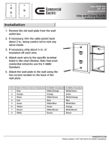
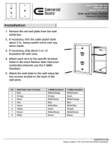
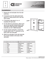
Installation
Installation Checklist
Install the cabinets by following these simple steps:
Step 1: Unpack the system
Step 2: Report any damage to the freight carrier
Step 3: If appropriate, remove any covers and/or doors
Step 4: If appropriate, remove the mounting plate assembly and store where
damage will not occur to the electronics
Step 5: Attach the cabinet to the wall (reference stickers inside the cabinet for
proper orientation if it is in question)
Step 6: Drill conduit entry holes if KO’s are not provided and attach conduit
where appropriate
Step 7: Pull all wire into the cabinet
Step 8: Test & Verify all wiring by directly connecting line to load - Correct any
faults and re-test wiring prior
to proceeding
Step 9: If applicable, re-install any control electronics removed in step #4
Step 10: Terminate discreet input control wiring
Step 11: Terminate network control wiring
Step 12: Test each Line/Load circuit for shorts
Step 13: Terminate the feed & load wiring to each relay
Step 14: Blow out dust, dirt, or debris which has accumulated in the cabinet
Step 15: Apply power to the system
Step 16: Verify proper operation of each relay using the override buttons
Step 17: Configure cabinet per owner’s requirements
WEB VERSION

Selection of a Mounting Location
Z-MAX Installation Guide
Page 7
Relay Cabinet Mounting
There are several steps required when mounting your relay cabinet:
Step 1: Install the flush mounting kit if appropriate
Step 2: Plan your conduit runs & electrical room layout
Step 3: Determine the appropriate methods for mounting your cabinet to the wall
Step 4: Mount the cabinet to the wall
Step 5: Install conduit, pull wire, and other items as required
Step 6: Proceed to Line & Load Voltage termination (page 15)
Selection of a Mounting Location
Choosing a mounting location for your cabinet is critical to the overall success and
ease of installation. Each style of cabinet has it’s unique wiring requirements which
must be observed. Please review the next few pages, which describe and illustrate
these requirements.
Suggested Mounting Heights
Although successful operation is completely independent of mounting height, the
suggested mounting heights below were selected to locate the cabinet at a
reasonable and accessible working height.
Environmental Considerations
• Cabinets generate heat (see table which follows). Make sure they are mounted in a
climate controlled space where the temperature will be 0-40
o
C (32-104
o
F) or 20-
30
o
C (68-86
o
F) if used as Emergency Lighting Power Equipment.
• Reinforce the wall for strength as required for weight and local code
• Clearance on left and right side of the panel should be maintained at 1
1
/
2
" or
greater
• Relays will click while in operation. Locate the panels where audible noise is
acceptable.
Figure 2-1: Relay Cabinet Max head load (BTU/hr.)
Cabinet Suggested Mounting height to bottom of
cabinet
24 Relay Cabinet 32" (826 mm)
48 Relay Cabinet 12" (318 mm)
Cabinet MAX BTU/HR
24 Relay Cabinet 583
48 Relay Cabinet 1166
WEB VERSION

Page 8
Preferred areas for conduit entry
Your relay cabinet has been designed to be easy to install with a variety of installation
options to fit many applications. However, there still are specific considerations which
must be made. One of these is the allowed, and in some cases disallowed, areas for
conduit entry. Disallowed areas are areas where conduit entry is impossible either due
to physical or code limitations. These areas are clearly marked in the following
illustrations. Once you recognize the disallowed areas for conduit entry, you can look
at the allowed areas. Each cabinet style has designated areas for low voltage and line
voltage conduit entry. Observation of these requirements will ensure smooth
installation and continued code compliance.
WEB VERSION

Preferred areas for conduit entry
Z-MAX Installation Guide
Page 9
Figure 2-2: 24 & 48 Relay Cabinets Conduit Entry (24 relay cabinet shown,
48 similar)
Low Voltage Area
High Voltage Area
Transformer located
underneath control
module
Grounding Points
Transformer
Connections
this area below
control module
High Voltage Pass
through below
control module
mounting plate
WEB VERSION

Page 10
Sample Electrical Room Layouts
The "right" layout for your application is a decision only you can make. The layouts
depicted in the following illustrations show some simple and effective systems which
you’re welcome to use and adapt to your particular installation.
Figure 2-3: Sample Electrical Room Layouts for all cabinets
W
A
L
L
W
A
L
L
Front View
Wiring Raceway
Class 2/PELV
Wiring to
Controls -
2 locations
Feed and/or
switch legs
to loads
Feed and/or
switch legs
to loads
Feed wiring to relays
W
A
L
L
Side View
Distribution panel
Top and Bottom Feed
and /or switch legs to loads
Surface Mounting Shown
front3
WEB VERSION

Mounting Provisions & Dimensions
Z-MAX Installation Guide
Page 11
Mounting Provisions & Dimensions
Figure 2-4: Z-MAX 24 Master & Remote relay cabinet mounting provisions
and dimensions
20 1/4
[514.35]
34
[863.6]
4
[101.6]
14 11/64
[359.83]
16 5/8
[422.4]
16 5/8
[422.4]
14 11/64
[359.83]
16
[406.4]
1 27/32
[46.8]
16
[406.4]
1 27/32
[46.8]
All Dimensions are in inches
[ ] are mm
LOW
VOLTAGE
CONDUIT
ENTRY
1-1/4" & 1-1/2"
6 PLACES
LINE / LOAD
CONDUIT
ENTRY
1" & 1-1/4"
6 PLACES
LOW VOLTAGE
CONDUIT ENTRY
1" & 1-1/4"
6 PLACES
LINE / LOAD
CONDUIT ENTRY
1" & 1-1/4", 2
PLACES PLUS
1-1/4" & 1-1/2", 3
PLACES
LINE / LOAD
CONDUIT ENTRY
1" & 1-1/4", 2
PLACES PLUS
1-1/4" & 1-1/2", 3
PLACES
LINE / LOAD
CONDUIT
ENTRY
1" & 1-1/4"
6 PLACES
LINE / LOAD CONDUIT ENTRY: 1" &
1-1/4", 4 PLACES PLUS 1-1/4" & 1-
1/2", 6 PLACES
WEB VERSION

Page 12
Figure 2-5: Z-Max 48 Relay cabinet mounting provisions and dimensions
16
[406.4]
2 13/32
[61.15]
16
[406.4]
2 13/32
[61.15]
36 5/8
[930.4]
14 11/64
[359.83]
14 11/64
[359.83]
36 5/8
[930.4]
4
[101.6]
54
[1371.6]
20 1/4
[514.35]
All Dimensions are in inches
[ ] are mm
LINE / LOAD CONDUIT
ENTRY
1" & 1-1/4", 2 PLACES
PLUS
1-1/4" & 1-1/2", 3 PLACES
LOW
VOLTAGE
CONDUIT
ENTRY
1-1/4" & 1-1/2"
6 PLACES
LINE / LOAD CONDUIT
ENTRY
1" & 1-1/4", 2 PLACES
PLUS
1-1/4" & 1-1/2", 3 PLACES
LOW VOLTAGE
CONDUIT
ENTRY
1" & 1-1/4"
6 PLACES
LINE / LOAD
CONDUIT
ENTRY
1" & 1-1/4"
12 PLACES
LINE / LOAD
CONDUIT ENTRY
1" & 1-1/4"
12 PLACES
LINE / LOAD CONDUIT ENTRY: 1" &
1-1/4", 4 PLACES PLUS 1-1/4" & 1-
1/2", 6 PLACES
WEB VERSION

Mounting Provisions & Dimensions
Z-MAX Installation Guide
Page 13
Step-by-step Mounting Instructions
Step 1: Locate where the cabinet will be hung on the wall. Choose a location in a
dry area that is convenient to the branch circuit panel.
Step 2: Leviton requires that cabinet mounting hardware reach through the
drywall to wall studs or other suitable solid backing. However, properly
sized struts and suitable hardware can also be used. The load must be
evenly distributed to the anchors without exceeding the recommended
anchor limit. Using drywall screws directly through drywall without a stud
is not acceptable. Make sure that adequate support at all points is
provided. For fully loaded cabinet weights, see “Product line product
capabilities Chart (all products shown)” on page 3..
Step 3: Remove the cover. Some cabinets may also require the removal of data
and/or grounding wires. Make sure that this occurs prior to removal of
the door and that they are reconnected when reinstalling the door. On
cabinets with hinges, simply lift the door off the hinges. On cabinets with
screws, remove the cover screws. Appropriately store the cover for
future use.
Step 4: On the (4) relay panels only, locate the mounting plate assembly
attached to the back of the enclosure. Locate the 4 mounting screws in
the 4 corners of the rear plate. Loosen these 4 screws. Lift the entire
assembly up and out of the enclosure.
Step 5: Prior to proceeding, reference “24 & 48 Relay Cabinets Conduit Entry (24
relay cabinet shown, 48 similar)” on page 9 which shows the location of
the mounting holes and allowed conduit entry locations for each cabinet
type.
Step 6: Prior to attaching the cabinet to any surface, verify that the top of the
cabinet is actually located at the top. Some cabinets have "up" arrows to
aid in this indication.
Step 7: Attach the cabinet to it’s prepared mounting surface as appropriate.
Step 8: Cut, punch, or remove knockouts for the desired conduit openings. Pay
special attention to any disallowed areas for conduit entry.
Step 9: Pull all wire, both line and low voltage as appropriate.
Step 10: Carefully & completely remove any dust, debris, metal particles, etc.
from inside the cabinet in preparation for wire termination and eventually
power up.
Step 11: Proceed to the next section.
WEB VERSION

Page 14
WEB VERSION
/