
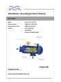
ALF Filter
Model : ALF-R, ALF-S, ALF-P
Standard (Steel) : ASME VIII or EN 13445
Standard (Glass fiber) : ASME X or EN13121
Valid for : 10S/15S/20S/30S
: 20P/30P/40P
: 20R/30R/40R/50R/60R/80R
English EN
Original manual
ALF Instruction Manual UM_Filter_100B03
ALFA LAVAL COPENHAGEN A/S
Installation, Operating & Safety Manual

Alfa Laval Copenhagen A/S
ALF – Installation, Operating and Safety Manual
The instructions given in this manual are intended as a general
instruction to Alfa Laval Filter type ALF
Alfa Laval reserves the right to make changes at any time without prior notice.
Any comments regarding possible errors and omissions or suggestions for improvement of this
publication would be gratefully appreciated. Please forward this information to the address below.
If further clarification regarding this manual is required, please contact your local Alfa Laval
representative.
Copies of this publication can be ordered from your local Alfa Laval Company.
This instruction replaces all previous manuals including
ALF instruction manual UM_Filter_100B01
ALF instruction manual UM_Filter_100B02
Published by: Alfa Laval Copenhagen A/S
Maskinvej 5
DK-2860 Søborg
Denmark
© Copyright Alfa Laval Copenhagen A/S
This manual and its content must not be copied, reproduced, transmitted or disclosed to any third
party without consent of Alfa Laval Copenhagen A/S.

Alfa Laval Copenhagen A/S
ALF – Installation, Operating and Safety Manual
Table of contents
1. Contents
1.
Contents ............................................................................................. 3
2.
Safety Instructions and Warnings ....................................................... 5
2.1
General Safety Regulations ............................................................... 6
2.2
Safety Regulations during Installation ................................................ 6
2.3
Safety Regulations during Operation and Maintenance .................... 6
2.4
Noise Emission .................................................................................. 6
2.5
Modifications and Reconstruction ...................................................... 7
3.
Storage guidelines ............................................................................. 8
3.1
Storage .............................................................................................. 8
3.2
Standstill ............................................................................................ 8
4.
Installation .......................................................................................... 9
4.1
Guidelines ......................................................................................... 9
4.2
Unpacking ......................................................................................... 9
4.3
Lifting ............................................................................................... 10
4.4
Foundation ...................................................................................... 11
4.5
Mechanical Installation .................................................................... 11
4.6
Electrical Installation ........................................................................ 15
4.7
Parts position ................................................................................... 16
5.
Main Components ............................................................................ 18
5.1
TYPE ALF-R .................................................................................... 18
5.2
TYPE ALF-S .................................................................................... 19
5.3
TYPE ALF-P .................................................................................... 20
6.
Operating instructions ...................................................................... 21
6.1
Field of Application .......................................................................... 21
6.2
Operating Principle .......................................................................... 21
6.3
Operating precautions ..................................................................... 21
6.4
Normal Operation ............................................................................ 23

Alfa Laval Copenhagen A/S
ALF – Installation, Operating and Safety Manual
6.5
ALF Filter Start, Operation and Shut down – 2Touch ....................... 25
6.6
ALF Filter Start, Operation and Shut down – S7 Panel .................... 28
7.
Maintenance .................................................................................... 31
7.1
Introduction ...................................................................................... 31
7.2
Safety Instructions ........................................................................... 31
7.3
Removal and Insertion of the Filter Basket ...................................... 33
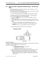
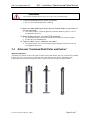
7.4
Alfa Laval “Combined Shaft Puller and Pusher” ............................... 35
8.
Trouble Shooting. ............................................................................. 36
9.
Spare Parts ...................................................................................... 38
9.1
Ordering Spare Parts ....................................................................... 38
9.2
Alfa Laval Service ............................................................................ 38
10.
Index ................................................................................................ 39
11.
APPENDIX A: Tables ....................................................................... 40
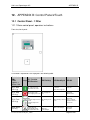
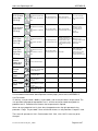
12.
APPENDIX B: Control Panel 2Touch ............................................... 43
12.1
Control Panel - 1 Filter ..................................................................... 43
13.
Appendix C: ALF Control Panel S7 .................................................. 63
13.1
Control Panel
-
1 Filter ..................................................................... 63

Alfa Laval Copenhagen A/S
ALF – Installation, Operating and Safety Manual
ALF Instruction Manual UM_Filter_100B03
Page 5 of 67
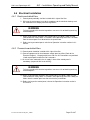
2. Safety Instructions and Warnings
The following symbols in this manual point out safety precautions. It means your
attention is needed and your safety is involved.
WARNING
This symbol is used to indicate the presence of a hazard, which can or will
cause severe personal injury, if the warning is ignored.
CAUTION
Certain passages of the text will be marked with a caution mark. This mark
indicates the presence of hazard, which will or can cause property damage if the
instructions are not observed.
NOTE
This type of instruction indicates a situation, which, if not avoided, could result in
damage to the equipment.

Alfa Laval Copenhagen A/S
ALF – Installation, Operating and Safety Manual
ALF Instruction Manual UM_Filter_100B03
Page 6 of 67
2.1 General Safety Regulations
The following general safety rules must be followed on every occasion:
• The installation and operating manual contains vital information that must be
considered during all handling of the ALF filter. All personnel who are in
contact with the equipment must read the operating and installation manual.
The operating manual should be kept available near the equipment.
• If the safety regulations are not followed, there is a risk of injuries as well as
damage to the machinery and the surrounding environment. If these safety
regulations have not been followed, Alfa Laval cannot be claimed responsible.
If manuals are translated to local language the unit complies with the European
Machinery Directive 2006/42/EC and EN ISO 12100-1/2:2003 standards.
For countries within the EU and the associated EFTA countries, manuals MUST
be available in local language before installing and operating the unit.
2.2 Safety Regulations during Installation
Only authorized and qualified personnel should carry out the installation.
All work on the machinery must be performed when it is not in operation and
the main power supply is switched off.
All local regulations regarding transport and lifting must be followed at all
times.
2.3 Safety Regulations during Operation and Maintenance
Never open the filter during operation
Never put hands, other parts of your body or foreign objects into the
machinery without making sure the mains supply has been switched off
2.4 Noise Emission
Peak level sound pressure level occur when the filter is flushing and back
flushing.
In an indoor installation the sound pressure level will be significantly higher due to
the reflection of sound from walls and surroundings.
In order to minimize the sound pressure level at the machinery, it is
recommended to install in a room with low reflection of sound.
WARNING
Always wear ear protection when working next to a filter in operation. High
sound pressure levels can occur at flushing or back flushing

Alfa Laval Copenhagen A/S
ALF – Installation, Operating and Safety Manual
ALF Instruction Manual UM_Filter_100B03
Page 7 of 67
2.5 Modifications and Reconstruction
Please note that the machinery must not be altered or modified in any way if not
directly approved by Alfa Laval.
Use of original spare parts and accessories guarantee a safe operation. Use of
parts from other manufacturers can lead to premature failure of the machinery,
cause damage to the machine and surrounding area and jeopardize the
warranty.
WARNING
Noise hazards
• Use ear protection in noisy environments.
Crush hazards
• Do not work under hanging load.
• Wear head protection during installation and maintenance of the
equipment.
Cut hazards
• Wear gloves when handling machined parts.

Alfa Laval Copenhagen A/S
ALF – Installation, Operating and Safety Manual
ALF Instruction Manual UM_Filter_100B03
Page 8 of 67
3. Storage guidelines
3.1 Storage
Unless otherwise agreed, Alfa Laval delivers the equipment ready to be put in
operation upon arrival and after installation.
If it is necessary to store equipment for a longer period (1 month or more), certain
precautions shall be made in order to protect and prevent unnecessary wear of
the equipment.
Filters shall be stored preferably in their packing case (ALU Pack) & in the
original wooden box and in an environment protected from rain, dust, sands &
direct sun. Storage temperature shall be maintained between -10 to +60
0
C (14 to
140°F) and the relative humidity between 15 and 95% RH.
NOTE
There should absolutely not be any ozone producing equipment in the
storage room, like operating electric motors or arc welding. Ozone destroys
many rubber materials.
Do not store organic solvents or acids in the storage room.
Avoid heat and ultraviolet radiation.
3.2 Standstill
If the machinery is to be out of operation for a period of 3 days or more, the
following precautions shall be taken:
• Drain the filter
• Flush the filter with potable water
Note
If the filter(s) is out of operation for more than three (3) days, then filter(s) shall
be drained and flushed with potable water in order to avoid corrosion on the
internal metallic parts.
3.2.1 Restart
• Visually check outside for defects
• Close Drain valves (option)
• Ensure proper venting of pipe system to avoid air pockets in system
• After start up - monitor the operation of the unit for approx. 10 minutes

Alfa Laval Copenhagen A/S
ALF – Installation, Operating and Safety Manual
ALF Instruction Manual UM_Filter_100B03
Page 9 of 67
4. Installation
4.1 Guidelines
For details on Dimensions, Connections, Loads, Service area, etc.: See the
order specific dimension drawing.
The ALF filter is either a complete machine or a partly completed machine
depending of what components the ordered filter consist of.
NOTE
It is the responsibility of the party that commissions/installs the filter to ensure
that the instructions given on the declaration of incorporation/ declaration of
conformity are followed prior to the first startup of the filter.
All electrical installations must be done in accordance with local regulations. A
certified electrician should carry out this job.
During working on the electrical installations the main power supply must be shut
off at all times.
For all signal cabling it is recommended to use screened cables only.
WARNING
Emergency stop must be installed as per local regulations.
4.2 Unpacking
When unpacking, take care not to damage the filter
Make sure that the ALF filter has not been damaged during the transport.
If transport damages are found, please contact local Alfa Laval agent.

Alfa Laval Copenhagen A/S
ALF – Installation, Operating and Safety Manual
ALF Instruction Manual UM_Filter_100B03
Page 10 of 67
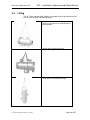
4.3 Lifting
The ALF filter should only be lifted by using proper lifting slings fitted to the ALF
filter as according to the following drawing.
Lifting of filter
s
mounted with lifting lugs.
Lifting lug is present on all according to the
lifting lug table.
Lifting of filter
s
without lifting lugs
Lifting
of
filter
s
for vertical installations:
Lifting lugs on the End cover flange.

Alfa Laval Copenhagen A/S
ALF – Installation, Operating and Safety Manual
ALF Instruction Manual UM_Filter_100B03
Page 11 of 67
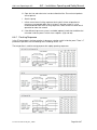
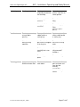
4.3.1 Lifting Lug Table
The following sizes are always supplied with lifting lugs:
ALF 15-S
ALF 20-S ALF 20-R
ALF 30-S ALF 30-R ALF 30-P
ALF 40-R ALF 40-P
ALF 50-R
ALF 60-R
ALF 80-R
Always use approved and certified equipment for the lifting. Refer to dimensional
drawing for the specific ALF filter for the weight of the equipment.
When lifting a filter, then use proper and approved rope slings and make sure
that the filter is prevented from tilting or rotating. Center of gravity is stated on the
dimensional drawing.
The ALF filter must be empty during lifting or transportation in order to avoid
unstable lifts and damage to the ALF filter.
WARNING
Always use lifting slings
with appropriate strength and dimension to handle the
weight of the ALF Filter
Always lift the ALF
filter by the lifting points, as shown above
Make sure that the ALF filter is empty before lifting.
4.4 Foundation
The ALF filters that are equipped with support feet or mounting brackets must be
fastened securely to the floor or a steel structure.
The maximum static foundation load calculation can be purchased on a
foundation drawing on request.
It is important that the foundation is made so that the filter is installed in
completely horizontal or vertical position to ensure correct fitting of piping
In vibrating environments or upon installation in earthquake zones loads on
nozzles and foundation bolting should be considered carefully prior to installation.
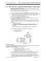
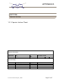
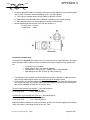
4.5 Mechanical Installation
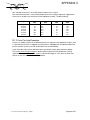
1. Make sure there is a sufficient service area according to below table for pulling
out the flow diverter shaft or filter basket for maintenance purposes.

Alfa Laval Copenhagen A/S
ALF – Installation, Operating and Safety Manual
ALF Instruction Manual UM_Filter_100B03
Page 12 of 67
Service distance for
Size (R, S, P)
(minimum)
Shaft
(mm above flange)
Basket
(mm from end cover
flange)
10 320 500
15 420 700
20 500 800
30 555 1050
40 650 1300
50 850 1600
60 1150 2150
80 1600
(from shell)
2600
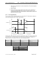
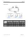
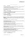
2. Proper Pipe Support shall be considered for the flushing pipe line. Otherwise due
to the high velocity, flushing pipe will be damaged. Suitable support shall be
considered for filter types ALF 30, ALF 40, ALF 50, ALF 60 and ALF 80.
3. Ensure the flow direction is correct. (Refer to section “Operating instructions”).
4. Flushing valve on ALF 20 and larger models are a wafer type butterfly valve. The
pipe work must allow the valve free entry into the pipe, when it turns.
5. Filter shall not be installed with the flow diverter shaft or actuator downwards.
6. Do not mount butterfly valves directly on the filter inlet or main outlet flanges.
There is a risk that the valve disc contacts the flange internals and could not be
opened or closed properly.
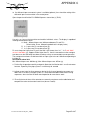
7. Non-return valves causes turbulent flows and is not recommended in front of the
filter. Ensure minimum 6 times pipe diameter from the non-return valve to the filter
inlet.
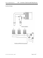
8. Flushing pipe can be connected to pipe system after a heat exchanger in order to
obtain back pressure for the flushing outlet. (See Installation example)
9. Flushing valve shall be tightened until the valve does not leak.
NOTE
Make sure the flushing valve is centred and not excessively tightened. There is
risk that the valve body can break during operation.
10. To avoid water hammer and excessive flow during back flushing initiation,
flushing pipe should be installed so that the pipe can be water filled at all times.
11. Make sure differential pressure (DP) between filter’s inlet & flushing outlet must
not exceed below values.
i. For (ALF 40, 50, 60 & 80) = 2.5 barg.
ii. For (ALF 10, 15, 20, & 30) =3.0 barg.
NOTE
DP pressure beyond above mentioned values could create serious damage on
the filter basket & other internal parts.

Alfa Laval Copenhagen A/S
ALF – Installation, Operating and Safety Manual
ALF Instruction Manual UM_Filter_100B03
Page 13 of 67

Alfa Laval Copenhagen A/S
ALF – Installation, Operating and Safety Manual
ALF Instruction Manual UM_Filter_100B03
Page 14 of 67
Installation Example

Alfa Laval Copenhagen A/S
ALF – Installation, Operating and Safety Manual
ALF Instruction Manual UM_Filter_100B03
Page 15 of 67
4.6 Electrical Installation
4.6.1 Electric controlled filters
1. Control panel preferably shall be installed within sight of the filter.
2. Wiring to the control panel must be in accordance to the electrical drawings and
the installation must comply with local regulations.
WARNING
Failure to comply with electrical regulations can cause risk of death by touching
electrified parts.
3. When using electrical actuators with junction box as an option, make sure the
junction box with safety switch is installed in close proximity to the filter. All cables
from the control panel must be wired via the junction box.
4. Before turning on control panel, refer the to Operation instruction section in this
manual.
4.6.2 Pneumatic controlled filters
12. Control panel should be installed within sight of the filter.
13. Connect compressed air hose between control panel and filter (Refer to the
Electrical Diagram). Use polyamide hoses Ø6 mm. Air Connections are provided
in both control panel and on the filter’s actuators.
14. A shut off valve mounted in the air supply in front of the control panel is
mandatory (not part of Alfa Laval delivery)
WARNING
Failure to comply with electrical regulations can cause risk of death by touching
electrified parts.
15. When using pneumatic actuators with junction box as an option, make sure the
junction box with safety switch is installed in close proximity to the filter’s body. All
cables from the control panel must be wired via the junction box.
16. Before turning on the control panel, refer to the Operation instruction section in
this manual.

Alfa Laval Copenhagen A/S
ALF – Installation, Operating and Safety Manual
ALF Instruction Manual UM_Filter_100B03
Page 16 of 67
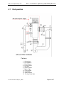
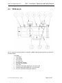
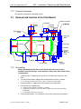
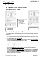
4.7 Parts position
Positions:
1. Service Area
2. Pipe Supports
3. Flow Direction
4. Flushing Valve
5. Actuators
6. Shut-Off Valve
7. Bypass Pipe
11. Flushing Pipe
14. Outlet Pipe
17. Shut-Off Valve
P Flushing Outlet Pipe

Alfa Laval Copenhagen A/S
ALF – Installation, Operating and Safety Manual
ALF Instruction Manual UM_Filter_100B03
Page 17 of 67
4.7.1 Piping Installation
The piping should be arranged in as short and easily assembled parts as
possible.
Size of piping should be appropriate for the size on the ALF filter (see dimension
drawing).
Choose piping details and associated equipment in materials that will meet the
demands by the specific process application.

Alfa Laval Copenhagen A/S
ALF – Installation, Operating and Safety Manual
ALF Instruction Manual UM_Filter_100B03
Page 18 of 67
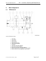
5. Main Components
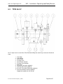
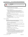
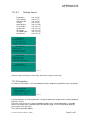
5.1 TYPE ALF-R
ALF-R: A pressure vessel of carbon steel Rubber lined inside for corrosion protection containing a
strainer for filtration of water
1.
Filter Body
2.
Filter Basket
3.
Flow Diverter
4.
Flushing Valve
5.
Flow Diverter Actuator
6.
Flushing Valve Actuator
7.
End Cover
8.
Ventilation Connection (optional)
9.
Drainage Connection (optional)
10.
Pressure Transmitter Connection (optional)
11.
Davit for Horizontal Version (optional on some models)
12.
Davit for Vertical Version (optional on some models)

Alfa Laval Copenhagen A/S
ALF – Installation, Operating and Safety Manual
ALF Instruction Manual UM_Filter_100B03
Page 19 of 67
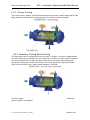
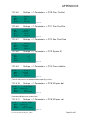
5.2 TYPE ALF-S
ALF-S: A pressure vessel of Stainless steel with a rubber lined end cover containing a strainer for
filtration of water
Filter Body
1.
Filter Body
2.
Filter Basket
3.
Flow Diverter
4.
Flushing Valve
5.
Flow Diverter Actuator
6.
Flushing Valve Actuator
7.
End Cover
8.
Ventilation Connection (optional on Size 20 and 30)
9.
Drainage Connection (optional on Size 20 and 30)
10.
Pressure Transmitter Connection (optional)

Alfa Laval Copenhagen A/S
ALF – Installation, Operating and Safety Manual
ALF Instruction Manual UM_Filter_100B03
Page 20 of 67
5.3 TYPE ALF-P
ALF-P: A pressure vessel of Glass Fibre Reinforced Polyester containing a strainer for filtration of
water
1.
Filter Body
2.
Filter Basket
3.
Flow Diverter
4.
Flushing Valve
5.
Flow Diverter Actuator
6.
Flushing Valve Actuator
7.
End Cover
8.
Ventilation Connection (optional)
9.
Drainage Connection (optional)
10.
Pressure Transmitter Connection (optional)
11.
Davit for Horizontal Version (optional)
Support feet (optional on 30 and 40)
Page is loading ...
Page is loading ...
Page is loading ...
Page is loading ...
Page is loading ...
Page is loading ...
Page is loading ...
Page is loading ...
Page is loading ...
Page is loading ...
Page is loading ...
Page is loading ...
Page is loading ...
Page is loading ...
Page is loading ...
Page is loading ...
Page is loading ...
Page is loading ...
Page is loading ...
Page is loading ...
Page is loading ...
Page is loading ...
Page is loading ...
Page is loading ...
Page is loading ...
Page is loading ...
Page is loading ...
Page is loading ...
Page is loading ...
Page is loading ...
Page is loading ...
Page is loading ...
Page is loading ...
Page is loading ...
Page is loading ...
Page is loading ...
Page is loading ...
Page is loading ...
Page is loading ...
Page is loading ...
Page is loading ...
Page is loading ...
Page is loading ...
Page is loading ...
Page is loading ...
Page is loading ...
Page is loading ...
-
 1
1
-
 2
2
-
 3
3
-
 4
4
-
 5
5
-
 6
6
-
 7
7
-
 8
8
-
 9
9
-
 10
10
-
 11
11
-
 12
12
-
 13
13
-
 14
14
-
 15
15
-
 16
16
-
 17
17
-
 18
18
-
 19
19
-
 20
20
-
 21
21
-
 22
22
-
 23
23
-
 24
24
-
 25
25
-
 26
26
-
 27
27
-
 28
28
-
 29
29
-
 30
30
-
 31
31
-
 32
32
-
 33
33
-
 34
34
-
 35
35
-
 36
36
-
 37
37
-
 38
38
-
 39
39
-
 40
40
-
 41
41
-
 42
42
-
 43
43
-
 44
44
-
 45
45
-
 46
46
-
 47
47
-
 48
48
-
 49
49
-
 50
50
-
 51
51
-
 52
52
-
 53
53
-
 54
54
-
 55
55
-
 56
56
-
 57
57
-
 58
58
-
 59
59
-
 60
60
-
 61
61
-
 62
62
-
 63
63
-
 64
64
-
 65
65
-
 66
66
-
 67
67


Alfa Laval ALF-P Installation, Operating & Safety Manual
- Type
- Installation, Operating & Safety Manual
Ask a question and I''ll find the answer in the document
Finding information in a document is now easier with AI
Related papers
-
Alfa Laval Astepo clean filler Owner's manual
-
-
-
-
-
-
-
-
-
Other documents
-
Artsound ASW55 W Datasheet
-
Alfa Network AWAP411 Quick Installation Manual
-
Bernard Controls AQ Range LOGIC Installation & Operation Manual
-
-
 Alf Reader Starter Kit Quick start guide
-
iNOXPA C-TOP Installation, Service & Maintenance Manual
-
 Bakers Pride Oven ALF-F User manual
-
 2Touch 2150 series Installation guide
-
-
Furuno FE800 Installation guide


