Fairchild Low Pressure Motorized Pressure Regulator User manual

Type
User manual

This manual is also suitable for

1
25
20
17
6
3
3
10
10
13
6
8
10
10
13
(3-200)
(40-200)
(20-180)
(20-100)
(20-60)
(60-100)
(3-150)
(7-400)
(15-700)
(0-15)
(0-35)
(3-150)
(7-400)
(15-700)
10
16
80
81
.5-30
6-30
3-27
3-15
3-9
9-15
.5-20
1-60
2-100
0-2
0-5
.5-20
1-60
2-100
360
290
285
150
80
80
260
200
201
208
206
302
200
201
208
48
38
38
20
11
11
43
28
28
17
28
41
28
28
17
48
38
38
21
11
11
43
28
28
17
28
41
28
28
17
25
20
20
10
6
5
64
14
14
13
14
21
14
14
13
25
20
20
10
6
5
14
14
13
14
21
14
14
13
Table 1. Estimated Full Range Pressure Adjusting Time (seconds) 12 VDC Supply
GENERAL INFORMATION
The DC Pulse Input unit allows incremental adjustment of
regulator output pressure and provides for various
adjustment times for full range operation.
The DC Pulse Input unit contains a Clock Generator/
Translator Board which allows for operation with a
12 VDC or 24 VDC pulse input signal for use with an
External Controller with a 12 VDC or a 24 VDC output.
[.03-2]
[0.4-2]
[0.2-1.8]
[0.2-1.0]
[0.2-.6]
[0.6-1]
[.03-1.5]
[.07-4]
[.15-7]
[ 00-.15]
[ 00-.35]
[.03-1.5]
[.07-4]
[.15-7]
26
21
19
8
4
4
26
11
11
8
12
16
11
11
8
FAIRCHILD 24XS SERIES M/P CONVERTERS
DC PULSE INPUT UNIT
Operating Manual
188
150
149
75
45
38
130
100
107
105
103
150
100
107
105
Mode of Operation
Full Step - High Full Step - Low Half Step - High Half Step - Low
Full Range Adjustment Times (seconds)
Regulator Pressure
Model Ranges Min. Max. Min. Max. Min. Max. Min. Max.
psig [BAR] (kPa)
Vacuum - 10 Outside of Specs.
13
11
10
4
2
2
13
6
7
4
6
8
6
7
4
(3-200)
(40-200)
(20-180)
(20-100)
(20-60)
(60-100)
(3-150)
(7-400)
(15-700)
(0-15)
(0-35)
(3-150)
(7-400)
(15-700)
10
16
80
81
.5-30
6-30
3-27
3-15
3-9
9-15
.5-20
1-60
2-100
0-2
0-5
.5-20
1-60
2-100
360
290
285
150
80
80
260
200
201
208
206
302
200
201
208
48
38
38
20
11
11
43
28
28
17
28
41
28
28
17
48
38
38
21
11
11
43
28
28
17
28
41
28
28
17
25
20
20
10
6
5
22
14
14
13
14
21
14
14
13
25
20
20
10
6
5
22
14
14
13
14
21
14
14
13
Table 2. Estimated Full Range Pressure Adjusting Time (seconds) 24 VDC Supply
[.03-2]
[0.4-2]
[0.2-1.8]
[0.2-1.0]
[0.2-.6]
[0.6-1]
[.03-1.5]
[.07-4]
[.15-7]
[ 00-.15]
[ 00-.35]
[.03-1.5]
[.07-4]
[.15-7]
18
15
14
8
4
4
16
12
11
8
12
16
12
11
8
188
150
150
75
45
38
130
100
107
105
103
150
100
107
105
Mode of Operation
Full Step - High Full Step - Low Half Step - High Half Step - Low
Full Range Adjustment Times (seconds)
Regulator Pressure
Model Ranges Min. Max. Min. Max. Min. Max. Min. Max.
psig [BAR] (kPa)
Vacuum - 10
2
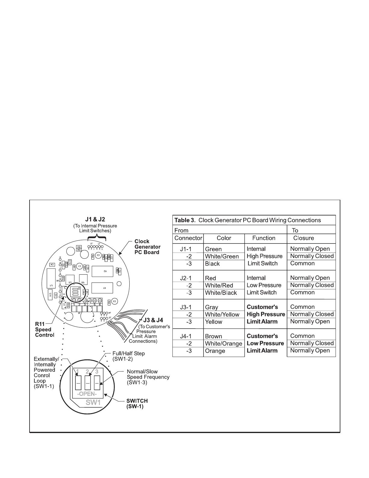
Figure 1. Clock Generator PC Assembly
Remove power from unit when changing
SW1-2 from half step mode to full step mode:
Switching from half step mode to full step
mode when the power is on can result in
motor operation at 1/2 its torque capability.
3.
4.
5.
6.
Turn the Normal/Slow Switch (SW1-3) to the Off/
Open position to achieve adjustment of pressure
over the full range when the stepper motor is
running at high speed.
Adjust the R11 Speed Control to fine-tune the
adjustment time. Refer to the column “High” of the
appropriate table on page 1 for the specific regula-
tor model and pressure range.
Turn the Normal/Slow Switch (SW1-3) to the On/
Closed position to achieve adjustment of pressure
over the full range when the stepper motor is
running at low speed.
Adjust the R11 Speed Control to fine-tune the
adjustment time. Refer to the column “Low” of the
appropriate table on page 1 for the specific regula-
tor model and pressure range.
ADJUSTMENTS
The following adjustments are provided:
Full/Half Step Mode Adjustment
NOTE:
1.
Normal/Slow Speed Frequency Selection
2.
Turn the Full/Half Step Switch (SW1-2) to the
Off/Open position for half step operation. Turn
the switch to the On/Closed position for full step
operation.
Refer to Tables 1. and 2. on page 1, to select the
required Full Range Adjustment Time.
Full/Half Step Mode
Normal/Slow Speed Frequency Selection
Externally/Internally Powered Control Loop
Limit Switch Adjustment
3
Figure 4. Controller (Pulse Input) using the non-isolated loop supply.
Figure 3. Controller (Pulse Input) using the dual isolated loop supply.
Adjustments (continued)
Externally/Internally Powered Control Loop
7.
Turn the Externally/Internally Switch (SW1-1) to
its appropriate configuration in accordance with
how the customer has his controller wired to the
Clock Generator Board. For more information,
see Figures 2, 3 & 4 below.
Additional Adjustments
Limit Switch Adjustment
Adjust the Low and High Limit Pressure Switches by
removing the Motor Assembly Cover and tuning the adjust-
ment screw on the top of the Motor Assembly. Decals
indicate the direction in which to turn the screws to change
the High and Low output limit pressures.
Figure 2. Controller (Pulse Input) using the isolated loop supply.
Service Kits
Table 5.
Model
OM-1000DCPI
Litho in USA
Rev. A 4/02
MAINTENANCE
Leakage
High Bleed
Difficult to adjust
TROUBLE-SHOOTING
Table 4. Trouble-Shooting
Probelm
Solution
Check Body Screw tightness.
Check Diaphragm.
Check Relief Pintle and Relief Seat
for damage or contamination.
Check Adjusting Screw and Ball
lubrication.
19495-1
19494-1
15704-1, -2, -3
15705-1, -2
For replacement of all elastomers and inter-
nal filters install the following Service Kits:
Model 10
Model 16
Model 80
Model 81
WARNING: Do Not attempt to repair circuit boards.
Unauthorized repair will void warranty.
The information set forth in the foregoing Installation, Operation and Maintenance Instructions shall not be
modified or amended in any respect without prior written consent of Fairchild Industrial Products Company. In
addition, the information set forth herein shall be furnished with each product sold incorporating Fairchild's unit
as a component thereof.
LEGAL NOTICE:
  • Page 1 1
  • Page 2 2
  • Page 3 3
  • Page 4 4

Fairchild Low Pressure Motorized Pressure Regulator User manual

Type
User manual
This manual is also suitable for

Ask a question and I''ll find the answer in the document

Finding information in a document is now easier with AI