Fairchild Motorized Pressure Regulator User manual

Type
User manual

Fairchild Motorized Pressure Regulator is a versatile device designed to provide precise and reliable pressure control in various industrial applications. With its TTL (+5 VDC) input, it allows for easy integration with digital control systems. The regulator features adjustable pressure ranges, enabling customization to specific requirements. Its stepper motor ensures accurate pressure adjustments, while the integral Translator Board facilitates control via clock pulses. Furthermore, it offers manual and computer control options, providing flexibility in operation.

Fairchild Motorized Pressure Regulator is a versatile device designed to provide precise and reliable pressure control in various industrial applications. With its TTL (+5 VDC) input, it allows for easy integration with digital control systems. The regulator features adjustable pressure ranges, enabling customization to specific requirements. Its stepper motor ensures accurate pressure adjustments, while the integral Translator Board facilitates control via clock pulses. Furthermore, it offers manual and computer control options, providing flexibility in operation.

1
7500
6000
5900
3000
1800
1500
4500
4500
3900
4800
6400
4500
4500
3900
(3-200)
(40-200)
(20-180)
(20-100)
(20-60)
(60-100)
(3-150)
(7-400)
(15-700)
(0-15)
(0-35)
(3-150)
(7-400)
(15-700)
10
16
80
81
.5-30
6-30
3-27
3-15
3-9
9-15
.5-20
1-60
2-100
0-2
0-5
.5-20
1-60
2-100
550
550
600
800
800
800
500
800
750
750
800
800
800
750
750
14300
11550
11400
6400
3200
3200
13000
8800
8250
6000
9600
12800
8800
8250
6000
300
300
350
500
600
500
450
450
300
800
800
450
450
300
Table 1. Estimated Full Range Pressure Adjusting Time (seconds) 12 VDC Supply
GENERAL INFORMATION
The TTL (+5) Input unit allows incremental adjustment of
regulator output pressure and provides for various ad-
justment times for full range operation.
The TTL Input unit contains an integral Translator Board
that converts clock pulses into control logic to drive the
stepper motor.
[.03-2]
[0.4-2]
[0.2-1.8]
[0.2-1.0]
[0.2-.6]
[0.6-1]
[.03-1.5]
[.07-4]
[.15-7]
[ 00-.15]
[ 00-.35]
[.03-1.5]
[.07-4]
[.15-7]
Vacuum - 10 Outside of Specifications
FAIRCHILD 24XS SERIES M/P CONVERTERS
TTL (+5 VDC) INPUT UNIT
Operation and Maintenance Instructions
Mode of Operation
Full Step Half Step
Regulator Pressure Total Pulses Max. Total Pulses Max.
Model Ranges 0-100% Frequency 0-100% Frequency
psig [BAR] (kPa) Output (Hz) Output (Hz)
7150
6050
6000
3200
1600
1600
6500
4800
4550
3200
4800
6400
4800
4550
3200
(3-200)
(40-200)
(20-180)
(20-100)
(20-60)
(60-100)
(3-150)
(7-400)
(15-700)
(0-15)
(0-35)
(3-150)
(7-400)
(15-700)
10
16
80
81
.5-30
6-30
3-27
3-15
3-9
9-15
.5-20
1-60
2-100
0-2
0-5
.5-20
1-60
2-100
800
800
800
800
800
800
800
800
800
800
800
800
800
800
800
14400
12000
11200
6400
3200
3200
12800
9600
8800
6400
9600
12800
9600
8850
6400
550
550
600
800
800
800
500
800
650
800
800
800
800
650
800
Table 2. Estimated Full Range Pressure Adjusting Time (seconds) 24 VDC Supply
[.03-2]
[0.4-2]
[0.2-1.8]
[0.2-1.0]
[0.2-.6]
[0.6-1]
[.03-1.5]
[.07-4]
[.15-7]
[ 00-.15]
[ 00-.35]
[.03-1.5]
[.07-4]
[.15-7]
Vacuum - 10
Mode of Operation
Full Step Half Step
Regulator Pressure Total Pulses Max. Total Pulses Max.
Model Ranges 0-100% Frequency 0-100% Frequency
psig [BAR] (kPa) Output (Hz) Output (Hz)
2
The Home Reference Switch is adjusted at the
factory to provide an electrical output signal at
0 psig output pressure.
ADJUSTMENT / OPERATIONS
Home Reference Switch Adjustment
NOTE:
1.
Manual Control Operation
1.
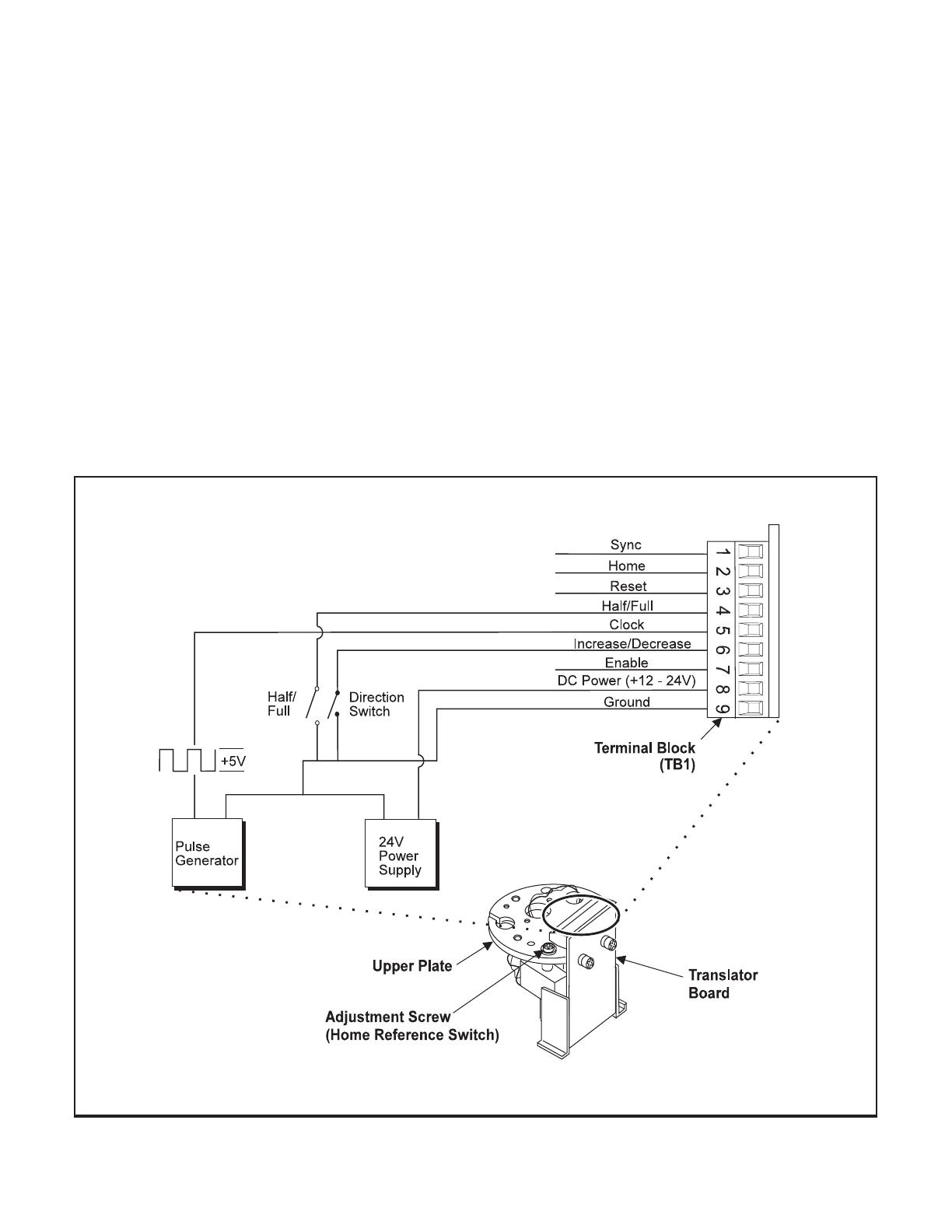
To change the Home Output Value turn the Adjust-
ment Screw clockwise to decrease pressure or
counterclockwise to increase pressure till the out-
put signal occurs. For more information, see Figure
1. “Manual Control Circuit” below.
Use a 12V or a 24V Power Supply together with a
Pulse Generator to generate step pulses. For
more information, see Figure 1. “Manual Control
Circuit” below.
Figure 1. Manual Control Circuit.
2.
3.
4.
5.
Refer to Tables 1. and 2. on page 1, to select the
Estimated Pulses for Pressure Range Adjustment.
Find the Regulator Model and the specific Pressure
Range being used.
Select Full or Half Step operation and set the pulse
generator frequency as indicated under the Max.
Frequency (HZ) column. The Total Pulses 0-
100% Output column shows the approximate num-
ber of pulses required to drive the Regulator over
the full range of pressure.
Turn the Pulse Generator to the On or Off position
to start or stop the stepper motor. Each pulse at the
Clock input to the Translator Board results in one
motor step of 1/200th of a shaft rotation of the
motor.
3
Figure 2. Computer Control Translator Board Timing Chart.
Adjustment / Operations (continued)
Computer Control Operation
1.
• Clock
1.
• Increase/Decrease
1.
To show the timing relationships between the sig-
nals applied to the Terminal Block (TB1) when a
computer is used to control the TTL Input unit, see
Figure 2. “Computer Control Translator Board Tim-
ing Chart” below.
A low input pulse on terminal 5 advances the motor
by one increment. This occurs on the rising edge of
the pulse.
When the input to terminal 6 is High, the motor
decreases the regulator output pressure. When the
input is Low, the motor increases the regulator
output pressure.
• Half/Full
1.
• Enable
1.
• Reset
1.
When the input to terminal 4 is Low, the controller
operates in Full Step Mode (200 steps per revolu-
tion of the motor shaft). When the input to terminal
4 is High, the controller operates in Half Step Mode
(400 steps per revolution of the motor shaft).
When the input to terminal 7 is Low, the Translator
Circuit is disabled. Power to the stepper motor is
turned off and input signals to the Translator Board
have no effect on the motor drive circuits.
When the external circuit connected to terminal 3
is in a Low state, the Translator Board Controller is
reset to a 0101 state.
Service Kits
Table 4.
Model
OM-1000TTLI
Litho in USA
Rev. B 06/07
MAINTENANCE
Leakage
High Bleed
Difficult to adjust
TROUBLE-SHOOTING
Table 3. Trouble-Shooting
Probelm
Solution
Check Body Screw tightness.
Check Diaphragm.
Check Relief Pintle and Relief Seat
for damage or contamination.
Check Adjusting Screw and Ball
lubrication.
19495-1
19494-1
15704-1, -2, -3
15705-1, -2
For replacement of all elastomers and inter-
nal filters install the following Service Kits:
Model 10
Model 16
Model 80
Model 81
WARNING: Do Not attempt to repair circuit boards.
Unauthorized repair will void warranty.
  • Page 1 1
  • Page 2 2
  • Page 3 3
  • Page 4 4

Fairchild Motorized Pressure Regulator User manual

Type
User manual

Fairchild Motorized Pressure Regulator is a versatile device designed to provide precise and reliable pressure control in various industrial applications. With its TTL (+5 VDC) input, it allows for easy integration with digital control systems. The regulator features adjustable pressure ranges, enabling customization to specific requirements. Its stepper motor ensures accurate pressure adjustments, while the integral Translator Board facilitates control via clock pulses. Furthermore, it offers manual and computer control options, providing flexibility in operation.

Ask a question and I''ll find the answer in the document

Finding information in a document is now easier with AI