Page is loading ...

© Copyright 2017 Liberty Pumps Inc. All rights reserved
Installer: Please leave this manual with the
owner / operator for future reference.
Prior to installation, record Model, Serial Number, and
Code Number from pump nameplate for future reference.
MODEL # ________________________
SERIAL # ________________________
CODE # ________________________
INSTALLATION
DATE ________________________
ASME112.3.4
CSA B45.9
7000 Apple Tree Avenue
Bergen, NY 14416
Phone: (800) 543-2550
Fax: (585) 494-1839
www.libertypumps.com
Contents
1.) General Information and Safety
Guidelines
2.) Installation
3.) Maintenance and Troubleshooting
Installation Manual 7212000E
Model 404 and 405 Automatic Drain Pump
404 Models Available:
404 Residential 115v
404/A (Alarm)
404/A-EYE (NightEye
®
Alarm)
404CV (Check Valve)
404CV/A
404CV/A-EYE
405 Models Available:
405 Commercial 115v
405HV Commercial 230v
405/A (Alarm)
405/A-EYE (NightEye
®
Alarm)
All Units Contain
Certified Pump
404CV Models Only

© Copyright 2017 Liberty Pumps Inc. All rights reserved 2
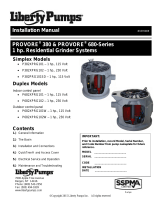
Figure 2: Product dimensions. Dimensions
are rounded to the nearest 1/8”
Before installation, read the following instructions carefully. Each Liberty pump is individually factory tested to ensure proper
performance. Closely following these instructions will eliminate potential operating problems, assuring years of trouble-free service.
Risk of electric shock. Always disconnect the pump from the power source before handling or making adjustments.
The electrical connections and wiring for a pump installation should only be made by qualified personnel.
Explosion hazard during installation. PVC cleaners, primers, and cements can release explosive vapors. These heavier than air
vapors can accumulate in the tank. The heat of soldering or sweating copper or other metal pipe can ignite these vapors causing a
violent explosion. If the unit is to be connected to copper discharge or vent piping, all solvent welded PVC joints must be allowed to
cure a minimum of 24 hours. The access cover must be removed to allow the tank to be thoroughly ventilated prior to sweating
copper pipe near the unit.
This pump is supplied with a grounding conductor and grounding-type attachment plug. To reduce the risk of electric shock, be
certain that it is connected to a Ground Fault Circuit Interrupter (GFCI) receptacle that meets the latest requirements per UL 943
including End of Life Provision and protection from Reverse Line-Load Miswire.
Always wear rubber boots when water is on the floor and you must unplug the pump.
DO NOT bypass grounding wires or remove ground prong from attachment plugs. DO NOT use an extension cord.
This pump requires a separate, properly fused and grounded branch circuit. Make sure the power source is properly sized for the
voltage and amperage requirements of the pump, as noted on the nameplate.
The electrical outlet shall be within the length limitations of the pump power cord, and at least 4 feet above floor level to minimize
possible hazards from flood conditions.
The installation must be in accordance with the National Electric Code, Uniform Plumbing Code, International Plumbing Code, as
well as all applicable local codes and ordinances.
Keep clear of suction and discharge openings. To prevent injury, never insert fingers into pump while it is plugged in.
DO NOT use this product for flammable or corrosive liquid.
DO NOT use this product in applications where human contact with the pumped fluid is common (such as swimming pools,
fountains, etc.)
NEVER dispose of materials such as paint thinner or other chemicals down drains, as they can chemically attack and damage
pump components, potentially causing product malfunction or failure.
Model 404 Do not use this pump in water over 140
F.
Model 405 Do not use these pumps in water over 180°F
DO NOT DO NOT use pumps in mud, sand, cement, oil or chemicals.
DO NOT modify the pump in any way.
DO NOT lift or carry pump by power cord.
DO NOT remove any tags from pump or cords.
If pump is installed during construction before power is available, it must
be protected from the environment to prevent water from entering
through the cord plug end, etc.
1. General Information and Safety Guidelines
2. Installation
Figure 1: Typical
residential installation
(this is a recommended
installation only).

© Copyright 2017 Liberty Pumps Inc. All rights reserved 3
DON’T!
Fig. 1 Piggyback plug installation.
TEMPORARY
MANUAL
OPERATION
NORMAL
INLET: The pump has two available ports: one on the top, the other on the side. Either can be used as a vent or inlet. Using the
appropriate piping (1-1/2” on the model 404 and 2” on models 405, 405HV) connect the fixture to the pump. Note: a trap shall be used
between the fixture and pump, a flange type is recommended. HAND-TIGHTEN TO PUMP. DO NOT OVERTIGHTEN OR CROSS-
THREAD.
A. DISCHARGE: HAND-TIGHTEN ONLY. Install a union just above the pump to facilitate removal if necessary for cleaning or
service. Install a check valve just above the union (as close to the pump as possible) to prevent the backflow of water after each
pump cycle.
B. VENT: Provision is made for a vent stack to allow extra volume for high suds conditions, and to ensure proper drainage of the
fixture. HAND-TIGHTEN ONLY. DO NOT CAP-OFF VENT. DO NOT use ONE-WAY QUICK-VENTS or AIR ADMITTENCE
VALVES as they will not guarantee proper fixture performance. The vent pipe should have a union to facilitate removal if required
and shall be connected directly to a building or house vent.
C. POWER CORD: The pump power cord is equipped with a grounding conductor and grounding-type 3-prong plug. It should be
connected to a separately fused, grounded, 3-wire grounding-type receptacle of 15-amp capacity with the proper voltage for your
model. Make sure all electrical wiring and connections are in accordance with the National Electric Code and all applicable local
codes.
MODEL 404 (including CV, /A, /A-EYE) - 115 volts
MODEL 405 (including /A, /A-EYE) - 115 volts
MODEL 405HV - 230 volts
Risk of electric shock. Always disconnect the pump from
the power source before handling or making adjustments.
DO NOT remove the plug or ground prong.
DO NOT use an extension cord.
D. CHECK VALVE: 404/CV, 404CV/A, and 404CV/A-EYE come with a check valve in order to meet ASME112.3.4 / CSAB45.9. This
check valve must be threaded into the discharge port of the 404 cover. HAND-TIGHTEN ONLY, WITH APPROPRIATE THREAD
SEALANT OR TEFLON TAPE. DO NOT CROSS THREAD.
E. ALARM: 404s and 405s with /A or /A-EYE come with a Liberty alarm. For instructions on using this alarm, please read the included
alarm manual.
The 404 and 405-series pumps come factory-equipped with a float switch mounted within the tank. These models come with two
cords - one to the float switch and the other to the pump motor. The switch cord has a series (piggyback) plug enabling the pump cord
to be plugged into the back of it (see Fig. 4). The purpose of this design is to allow temporary manual operation of the pump.
For automatic operation using Liberty's supplied switch, the two cords should be interconnected and plugged into a separately fused,
grounded outlet of proper amp capacity for your selected pump model. (See the pump’s nameplate for electrical specifications of your
model.) Both cords are equipped with 3-prong plugs and must be plugged into a properly grounded 3-wire receptacle. DO NOT
REMOVE THE GROUND PRONGS.
Figure 3: Switch / power cord use.
Figure 4: Pump float switch tether length.

© Copyright 2017 Liberty Pumps Inc. All rights reserved 4
For manual operation, or in the event of switch failure, the pump cord can be separated and plugged into the electrical outlet, directly
bypassing the switch. 208-230V single phase pumps should only be operated without the float switch by using the circuit breaker or
panel disconnect. Do not let the pump run dry for extended periods.
Application: The 404 and 405-series drain pumps are designed for use in gray wastewater applications. They will handle small debris
and solids such as laundry lint (up to 3/8”) associated with normal gray water drainage from a sink. Larger solids should be kept out of
the pump system. The 405-series is designed for commercial applications where higher temperature drain water (up to 180 degrees F.)
may be used.
Each unit is individually factory tested to ensure proper adjustment and operation. If the unit fails to operate properly, re-read the
instructions to see that they have been followed correctly. Routine maintenance is not required on the pump itself, but associated
connections may require occasional attention. Lint and foreign objects should be removed from the trap periodically. The check valve
on the discharge should also be checked for freedom of operation at the same time.
The pump is automatically turned on and off by use of a float switch mounted within the tank. This switch can be easily removed and
checked for operation by removing the access cover located on top of the unit. Once the access cover has been removed a rubber plug
must be lifted to free up the switch cord. The switch is mounted to a rod which can be removed by lifting or pulling upward.
IMPORTANT: Do not adjust the tether length. If replacing the switch, make sure to maintain the correct tether length for your
model per the following diagram. (Tether length is the distance of cord measured between the clamp and top of float switch.)
NOTE: Liberty Pumps, Inc. assumes no responsibility for damage or injury due to disassembly beyond float removal in the field.
Disassembly, other than at Liberty Pumps or its authorized service centers, automatically voids warranty.
Problem
Cause
Correction
Pump will not turn
on or shut off.
Blown fuse or other interruption of
power; improper voltage.
Check that the unit is securely plugged in.
Have an electrician check all wiring for proper
connections and adequate capacity.
Plugged vent, or quick-vent in use.
Be sure that an unrestricted vent at least 1-¼”
in diameter is in use. Quick-vents shall not be
used.
Defective switch or build-up on tank
wall restricting free movement of
float switch.
*Remove access cover and check that float is
free to move. If build-up restricts float, clean
and reinstall. If defective, replace switch.
Pump runs or hums
but does not pump.
Discharge is blocked or restricted.
Check the discharge line for blockage,
including ice if the line passes through or into
cold areas.
Check valve is stuck closed or
installed wrong.
Remove and examine for freedom of
operation and proper installation.
Total lift height has been reached
(see Fig. 2)
Try routing pipe to a lower level. If not
possible, another pumping station may be
required at a level of roughly half the total lift.
Pump impeller is jammed.
*Disassemble the receiver and bottom base
of pump. Remove foreign material.
Reassemble.
Trap or inlet piping is clogged.
Check the trap and inlet piping for restrictions.
Pump short-cycles.
Plugged vent, or quick-vent in use.
Be sure that an unrestricted vent at least 1-¼”
in diameter is in use. Quick-vents shall not be
used.
Defective switch.
*Remove access cover and check that float is
free to move. If build-up restricts float, clean
and reinstall. If defective, replace switch.
Check valve was not installed, is
stuck open, or is leaking.
Remove and examine for freedom of
operation and proper installation.
3. Maintenance and Troubleshooting

© Copyright 2017 Liberty Pumps Inc. All rights reserved 5
Pump runs
periodically when
fixtures are not in
use.
Check valve was not installed, is
stuck open, or is leaking.
Remove and examine for freedom of
operation and proper installation.
Faucets are dripping.
Repair faucets to eliminate dripping.
Water or soap suds
come out of vent
pipe.
Vent pipe is too short or too small in
diameter.
Be sure that an unrestricted vent at least 1-
¼” in diameter is in use.
Defective switch.
*Remove tank cover and check that float is
free to move. If build-up restricts float, clean
and reinstall. If defective, replace switch.
Rate of in-flow exceeds pump
output.
Use valve on the inlet to reduce rate of inflow.
Pump operates
noisily.
Foreign objects in impeller cavity.
*Disassemble the receiver and bottom base
of pump. Remove foreign material.
Reassemble.
Piping to house structure is too
rigid.
Replace a portion of the discharge pipe with
rubber hose to absorb noise.
MODEL 404 AND 405
PERFORMANCE CURVES AT 80° F WATER TEMP
0
5
10
15
20
25
30
35
40
0 10 20 30 40 50 60
FLOW (GPM)
HEAD (FEET)
MODEL 404
MODEL 405
405 @ 180°F
Figure 5: Performance curves for 404 and 405.

© Copyright 2017 Liberty Pumps Inc. All rights reserved 6
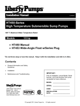
Liberty Pumps, Inc. warrants that its products are free from all factory defects in material and workmanship for a period of
3 years from the date of purchase. The date of purchase shall be determined by a dated sales receipt noting the model
and serial number of the pump. The dated sales receipt must accompany the returned pump if the date of return is more
than 3 years from the "CODE" (date of manufacture) number noted on the pump nameplate.
The manufacturer's sole obligation under this Warranty shall be limited to the repair or replacement of any parts found by
the manufacturer to be defective, provided the part or assembly is returned freight prepaid to the manufacturer or its
authorized service center, and provided that none of the following warranty-voiding events have taken place.
The manufacturer shall not be liable under this Warranty if the product has not been properly installed; if it has been
disassembled, modified, abused or tampered with; if the electrical cord has been cut, damaged or spliced; if the pump
discharge has been reduced in size; if the pump has been used in water temperatures above the advertised rating, or in
water containing sand, lime, cement, gravel or other abrasives; if the product has been used to pump chemicals or
hydrocarbons; if a non-submersible motor has been subjected to excessive moisture; or if the label bearing the serial,
model and code number has been removed. Liberty Pumps, Inc. shall not be liable for any loss, damage or expenses
resulting from installation or use of its products, or for indirect, incidental, and consequential damages, including costs of
removal, reinstallation or transportation.
THE WARRANTIES SET FORTH ABOVE ARE IN LIEU OF ALL OTHER WARANTIES, EXPRESSED OR IMPLIED,
INCLUDING WITHOUT LIMITATION, ANY WARRANTY OF MERCHANTABILITY OR FITNESS FOR A PARTICULAR
PURPOSE, AND ALL SUCH OTHER WARRANTIES ARE HEREBY DISCLAIMED AND EXCLUDED BY LIBERTY
PUMPS, INC.
4. 3 Year Limited Warranty
/