Page is loading ...

DT-305
360º Dual Technology Low
Voltage Occupancy Sensor
Ceiling Mount
Quick Start Guide
THIS UNIT IS PRESET FOR BASIC
OPERATION AS DESCRIBED IN THIS
GUIDE. ADJUSTMENT IS OPTIONAL.
For full operational details, adjustment and
more features of the product, see the Installation
Instructions at www.wattstopper.com
Installation shall be in accordance with all
applicable regulations, and codes.
SENSOR PLACEMENT 10’ MAX. HEIGHT
MOUNTING
WARNING
TURN POWER OFF AT CIRCUIT BREAKER
BEFORE INSTALLING POWER PACKS.
Load #1
Load #2
(Optional)
DT-305
Standard wiring with local off switch
Rear Housing
Depluggable
Terminal
Front Cover
Ceiling
Spring Clips (2)
Blue
Control Out
+24V
Common
Low Voltage
Class 2
Line
Voltage
Line
Neutral
Feed Through
Power Pack
Black
Red
#1 #2
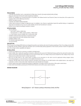
Line Voltage
Switches
LVS-1
Load
Rear Housing
Depluggable
Terminal
Front Cover
Ceiling
Spring Clips (2)
Blue
Control Out
Black
+24V
Low Voltage
Class 2
Line Voltage
Line
Neutral
Feed Through
Power Pack
Man.Switch
Red
DT-305
Manual-On wiring with low voltage momentary switch
Common
For low voltage
momentary switch set
DT-305 DIP switches:
1 = Off
2 = On
3 = On
Man.Switch
Common
Jumper
Back
of
LVS-1
CONNECTING WIRES
• Care should be taken to separate high voltage power from low voltage (Class 2) control wiring.
• All connections to sensor are low voltage, Class 2.
Rear
housing
Depluggable
terminal
4" Octagonal J-Box
(at least 1.5" deep)
Front
cover
Ceiling
Screws
To octagon box:
Rear
housing
Depluggable terminal
Front
cover
Ceiling
Spring clips (2)
Through ceiling tile:
Sensor
28'
30'
Sensor
Pendant xtures
Do NOT mount a ceiling sensor above a suspended
fixture. Use a ceiling/wall mount sensor mounted to
the wall below the plane of the bottom of the fixture.
Hot air supply
6’
Sensor
Mount sensor at least 6’ away from hot air supply
White
Black
Red
Line Voltage
Wire Color Legend

FACTORY PRESET OPERATION
Time delay 20 minutes
LED indicators Enabled
ON Mode
Auto-ON: Both techs must activate to
turn on load, either one keeps it on.*
PIR sensitivity High
Ultrasonic 80%
* DIP switch setting must be changed when using a low
voltage momentary switch. See wiring diagram.
Warm-up Period
Warm-up occurs during installation and after power outages
lasting 5 minutes or more. Initially, the load turns ON for 30
to 60 seconds. If there is no detection within 1-minute the
load turns off. If occupancy is detected, remains ON until the
space is vacated and the time delay has elapsed.
TROUBLESHOOTING
Lights do not turn on when entering the room.
Neither LED
Flashes
1. Check that the circuit breaker has been turned back on.
2. Check all sensor and power pack wire connections.
3. Check for 24VDC input to the sensor between the red and black low voltage wires.
• If 24VDC is present, replace the sensor.
• If 24VDC is not present, check the high voltage connections to the power pack.
• If high voltage connections are good and high voltage is present, replace the power pack.
Red LED does
not flash
1. When power is initially applied to the sensor, there is a warm-up period of 30 to 60 seconds before the
LED becomes active.
2. Make sure PIR sensitivity is set to 100% (DIP switch #8 is in the “on” position).
Green LED does
not flash
Ultrasonic sensitivity setting may need to be increased. Turn adjustment trimpot clockwise until the LED
begins to flash when movement occurs.
Green LED is on
continuously
Check ultrasonic sensitivity trimpot. Fully counterclockwise position is the override for the sensor. Turn
trimpot clockwise until LED flashes only when movement occurs in the desired coverage area.
Red and Green
LEDs flash
1. Check all sensor and power pack connections.
2. Check if Light Level is connected.
• If so, verify Light Level functionality is required and press and hold the Light Level button for 5
seconds to make sure it is not holding OFF the load.
• If Light Level functionality is not required reference the wire diagrams for proper wire connections.
3. Check for 24VDC at the power pack blue and black wire connections to sensor while sensor is active.
• If there is no voltage, replace the sensor.
• If there is voltage, check for 24VDC between the blue and black wire at the power pack. If 24VDC is
present and the relay is not closing, replace the power pack.
• If 24VDC is not present, check for a break in the low voltage wiring.
Lights do not turn off automatically.
Green LED flashes Reduce ultrasonic sensitivity by turning adjustment pot counter-clockwise until it only flashes when
movement occurs.
Red LED flashes
briefly and Green
LED does not flash
Check to see if you have used the Manual Switch connection. Do not connect anything to this terminal
if you are not using a low voltage momentary switch between the sensor and power pack.
Red LED randomly
flashes
Reduce PIR sensitivity by turning DIP switch 8 to the off position.
Lights do not turn
off
1. Check all sensor and power pack wire connections.
2. Disconnect power pack blue wire.
• If lights do not turn off, check power pack wiring. Replace the power pack if necessary.
• If lights turn off, the problem may be the sensor or wiring between the sensor and power pack.
3. Reconnect the blue wire.
• Turn sensitivity and time delay to minimum, and allow the sensor to time out.
• If lights turn off, the sensor is working properly – adjust sensitivity and time delay for the sensor.
• If lights do not turn off, check the wiring between the sensor and power pack.
• If wiring is correct, replace the sensor.
5/2008
09809r2
Please
Recycle
2800 De La Cruz Blvd.
Santa Clara, CA 95050
Phone: 800.879.8585
www.wattstopper.com
/