
Wattstopper
®
Ultrasonic Low Voltage Occupancy Sensor with Manual On Feature (v3)
Détecteur de présence à ultrasons basse tension avec marche en mode manuel (v3)
Sensor de ocupación ultrasónico de bajo voltaje con función de encendido manual (v3)
Installation Instructions • Instructions d’Installation • Instrucciones de Instalación
No: 24254 – 01/19 rev. 2
Catalog Numbers • Les Numéros de Catalogue • Números de Catálogo: UT-305-1, UT-305-2, UT-305-3
Country of Origin: Made in China • Pays d’origine: Fabriqué en Chine • País de origen: Hecho en China
SPECIFICATIONS
Voltage ................................18-28VDC/VAC, half wave rectified AC
Current Consumption ...............................................................25mA
Power Supply ...........................................Wattstopper Power Packs
Operating Temperature .............................32° to 131°F (0° to 55°C)
Time Delay Adjustment ............................30 seconds to 30 minutes
Walk-Through Mode .......... 3 minutes if no activity after 30 sec.
Test Mode .................................... 5 sec. upon DIP switch reset
Ultrasonic Coverage
Model UT-305-1 ..................................................... up to 500 ft
2
Model UT-305-2 ................................................... up to 1000 ft
2
Model UT-305-3 ................................................... up to 2000 ft
2
Sensitivity Adjustment ............. Minimum to Maximum (trimpot)
Frequency .......................................................................40kHz
UL & CUL Listed for use with Wattstopper Power Packs
U.S. Patents: 7,277,012
DESCRIPTION AND OPERATION
The Wattstopper UT-305 sensors turn lighting systems on and off
based on occupancy.
The UT-305 can be configured to turn lighting on, and hold it on as
long as it detects cccupancy. After no movement is detected for a user
specified time (5 to 30 minutes) the lights are switched off. A “walk-
through” mode can turn lights off after only 3 minutes, if no activity is
detected after 30 seconds of an occupancy detection.
The UT-305 operates on 24V supplied by Wattstopper Power Packs.
The sensors can operate on 24VDC, 24VAC, or half wave rectified AC.
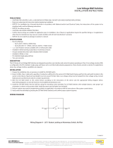
COVERAGE PATTERN
The UT-305 is available in 3 models. Each model has a different size
coverage pattern. The coverage shown represents walking motion at a
mounting height of 8 to 10 feet. For building spaces with lower levels of
activity or with obstacles and barriers, coverage size may decrease.
0
5'
12'
16'
23'
0
5'
16'23'33' 12'
12'
16'
23'
12' 16' 23' 33'
UT-300/305-3
UT-300/305-2
UT-300/305-1
UT-300/305-3
HALLWAY
APPLICATIO
N
PLACEMENT GUIDELINES
Depending upon obstacles such as furniture or partitions, the area
of coverage may be less or more than the sensing distances shown
in the coverage pattern. This must be considered when planning the
number of sensors and their placement. It is also recommended to
place the sensor 4 to 6 feet away from air supply ducts.
Mount the sensor to the ceiling. The UT-305 is designed for a
ceiling height of about 8-10 feet. Mounting above or below this range
will significantly affect the coverage patterns. As a general rule, each
occupant should be able to clearly view the sensor.
Open Office Area Coverage: To get complete coverage in an open
office area, install multiple sensors so that there is approximately
20% overlap with each adjacent sensor’s ultrasonic coverage area.
2QH87
&RYHUDJH$UHD
8OWUDVRQLF
2YHUODS

2
LVS-1
Load
Rear Housing
Depluggable
Te
rminal
Front Cover
Ceiling
Spring Clips (2)
Blue
Control Out
Black
+24V
Low Voltage
Class 2
Line Voltage
Line
Neutral
Feed Through
Power Pack
Man.Switch
Red
UT-305
Common
For low voltage
momentary switch, set
DIP switch #6 ON
Man.Switch
+24V
Jumper
Back
of
LVS-1
Load #1
Load #2
(Optional)
UT-305
Rear Housing
Depluggable
Te
rminal
Front Cover
Ceiling
Spring Clips (2)
Blue
Control Out
+24V
Common
Low Voltage
Class 2
Line
Voltage
Line
Neutral
Feed Through
Power Pack
Black
Red
#1 #2
Line Voltage
Switches
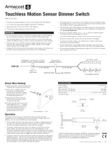
WIRING DIRECTIONS
Each Wattstopper BZ series power pack can supply power for 5 UT-305 sensors.
When using more sensors than this, multiple power packs are required.
Refer to the wiring diagram for the following procedures:
Connect the low voltage:
• RED wire (+24VDC) from power pack to the +24V terminal on the sensor.
• BLACK wire (Return) from power pack to Common terminal on the sensor.
• BLUE wire from power pack to Control Out terminal on sensor.
To add a manual switch such as the LVS-1 Momentary Toggle Switch, or RS2-3
Low Voltage Momentary Switch to the above applications–connect:
• Wire from one side of switch to +24V terminal on sensor.
• Wire from other side of switch to Man Switch terminal on sensor.
WARNING: TURN THE POWER OFF AT THE
CIRCUIT BREAKER BEFORE WIRING.
UT-305
Ultrasonic
Occupancy Sensor
U.S.Patents:
5,640,113
Patent Pending
40kHz Ultrasonic
+24VDC/VAC
Connect to Watt Stopper
Class 2 Power Packs
For Indoor Use Only
03624r2
Control Out.
Man. Switch
+24V
Common
LISTED
88T9
Appliance
Control
v3
Wiring
terminals
CONNECTING WIRES
• Care should be taken to separate high voltage power from low voltage (Class 2) control wiring.
• All connections to sensor are low voltage, Class 2.
Standard wiring with local off switch Manual-On wiring with low voltage momentary switch

3
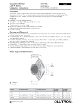
MOUNTING THE SENSOR
Directly to Ceiling
1. Attach the plastic spring clips to the edge of the sensor in the slots provided.
2. Cut a 3.5” to 4” round hole in the acoustic ceiling tile at the mounting location. A 3.5” hole
is recommended for a secure fit.
3. Pull the low voltage wire from the power pack to the sensor through the hole.
4. Connect the low voltage wires to the appropriate terminals on the sensor.
5. Push the sensor up through the hole until the Spring Clips hold the sensor securely in
place.
6. Snap the front cover onto the sensor.
Using an Octagonal J-Box
1. Pull the low voltage wires from the power pack into the J-Box through the conduit
knockout.
2. Connect the low voltage wires to the appropriate terminals on the sensor.
3. Loosen the appliance mounting screws attached to the J-Box
4. Align the sensor in the J-Box so that the mounting screws on the box match the key
holes on the sensor’s rear housing.
5. Push the sensor up into the J -Box and twist it so that the mounting screws are seated in
the keyhole slots.
6. Tighten the two screws to secure the sensor to the J-Box.
7. Snap the front cover onto the sensor.
'HSOXJJDEOHWHUPLQDO
5HDU
+RXVLQJ
2FWDJRQDO-%R[
DWOHDVWGHHS
)URQW
&RYHU
&HLOLQJ
6FUHZV
J-Box Mount
SENSOR ADJUSTMENT
NOTE: This unit is pre-set for basic operation as described in this guide. Adjustment is optional.
The sensors are factory preset to allow for quick installation in most applications.
Verification of proper wiring or coverage, or customizing the sensor’s settings can
be done using the following procedures. To make adjustments, open the Front
Cover with a small screwdriver.
Before making adjustments, make sure the office furniture is installed, lighting
circuits are turned on, and the HVAC systems are in the overridden/ on position.
VAV systems should be set to their highest airflow. Set the Time Delay to the
desired settings. See DIP Switch Setting.
To Test Occupancy Sensors
1. Ensure the Time Delay is set for Test Mode* using the “Test Mode/20
minutes” setting. (DIP Switches 1, 2, & 3 are OFF).
2. Ensure that the Ultrasonic Sensitivity trimpot is set to about 70%, clockwise.
3. Remain still. The LED should not flash. The lights should turn off after 5
seconds. (If not, see Troubleshooting.)
4. Move about the coverage area. The lights should come ON. Adjust the Ultrasonic Sensitivity as necessary to provide the desired
coverage (Green LED indicates activation from the ultrasonic sensor).
When testing and adjustment are complete, reset DIP Switches to the desired settings, and replace the cover on the sensor.
*Test Mode is a temporary state that starts when you first set the sensor’s DIP Switches for the “Test Mode/20 minutes” (Switches 1, 2,
3 OFF). If you need to invoke the Test Mode and the DIP Switches are already set for Test Mode/20 minutes, toggle DIP Switch 1 ON,
then back to the OFF position. This provides a 10 minute test period. During the test period, the Time Delay is only 5 seconds.
.H\KROHVORWV
IRUPRXQWLQJWR
RFWDJRQDOER[
'RXEOHJDQJ
PXGULQJ
PRXQWLQJKROHV
',3VZLWFKHV
21
(&(
8OWUDVRQLF
WUDQVGXFHU
FRQHV
8OWUDVRQLF
DFWLYLW\
/('*UHHQ
/LJKWOHYHO
SXVKEXWWRQ
8OWUDVRQLF
VHQVLWLYLW\WULPSRW
Rear
housing
Depluggable terminal
Front
cover
Ceiling
Spring clips (2)
Ceiling Mount

4
DIP SWITCH SETTING
Time Delay: Switches 1, 2, 3
The sensor will hold the lights ON as long as occupancy is detected. The time delay countdown starts when no
motion is detected. After no motion is detected for the length of the time delay, the sensor will turn the lights OFF.
Walk-Through Switch 4
Walk-Through mode turns the lights OFF three minutes after the area is initially occupied, if no motion is
detected after the first
30 seconds. If motion continues beyond the first 30 seconds, the selected time delay applies.
Service: Switch 5
To override all sensor functions, set DIP Switch 5 to the ON position. The green LED will come on and stay on
for the duration of the override. This bypasses the occupancy control functions of the sensor, but still allows
the lights to be manually controlled with a light switch, if one is installed.
On Mode: Switch 6
The Manual ON function is facilitated by installing a momentary switch such as a Wattstopper LVS-1
Momentary Toggle Switch, or RS2-3 Low Voltage Momentary Switch. This switch connects to the sensor’s
Manual (Man.) Switch and +24V terminals as shown in the wiring diagram. Each time the switch is pressed,
the load changes state. The sensor’s operation as related to the manually operated switch is determined by
the setting for DIP Switch 6.
Manual On: In this mode, the switch is required to turn ON the load. The sensor is then used to keep the load
on, based on occupant activity. After the time delay ends, if there is no movement detected within the
30 second re-trigger period the manual switch must be used to turn ON the load.
Automatic On: This mode uses occupancy as well as switch activation to turn the load ON. A manual switch
provides the following additional functionality:
1. The load can be turned ON by manual switch activation and it stays on as long as occupancy is detected. The sensor time delay
operates as programmed. When the load turns OFF due to lack of occupancy detection, the load can be turned ON again by
occupancy detection or switch activation.
2. Activating the manual switch while the load is ON turns the load OFF.
• When the load is turned OFF manually, as long as the sensor continues to detect occupancy the load stays OFF. For the
selected time delay, the lights stay OFF and the sensor reverts to the automatic-on mode.
• When the load is turned OFF manually, pressing the switch again turns the load ON and the sensor reverts to the automatic-on mode.
• Once the sensor returns to automatic-on mode, either the switch or occupancy detection can turn the load ON.
OVERLOAD PROTECTION
The occupancy sensor has a built in overload protection function that will automatically turn OFF the control output when the load
current exceeds 200mA. The sensor LED will then blink rapidly (~ 10Hz) to provide a visual indication of an overload condition. When
the load current is corrected or returns to normal, the control output will turn back ON.
TROUBLESHOOTING
For any unexpected operation:
1. Check DIP switch settings.
2. Make sure the switches are set according to the defined settings in the DIP Switch Setting chart.
Lights do not turn on with occupancy, and the LED does not ash:
1. Check that the circuit breaker has been turned back on.
2. The Ultrasonic Sensitivity setting may need to be increased.
3. Turn clockwise as needed.
4. Check all sensor and power pack wire connections.
5. Check for 24V input to the sensor.
• If 24V is present, replace the sensor.
• If 24V is not present, check that high voltage is present to power pack.
If it is, replace power pack.
Lights do not turn off automatically:
1. The sensor may be experiencing activations from outside the controlled area or from some type of interference (see “Unwanted
Sensor Activations” below).
2. Check all sensor wire connections.
3. Disconnect power pack’s blue wire:
• If the lights do not turn off, replace power pack. Reconnect blue wire.
• If the lights turn off, the problem may be in the sensor–to check:
• Reconnect the blue wire.
• Turn sensitivity and time delay to minimum and allow the sensor to time out.
If the lights turn off, the sensor is working properly (see number 1, above, and “Sensor Adjustment” for readjustment of sensor).
4. Set sensitivity and time delay to minimum and allow the sensor to time out.
If the lights turn off, the sensor is working properly (see number 1, above, and “Sensor Adjustment” for readjustment of sensor).
Switch#
5 minutes
10 minutes
15 minutes
20 minutes
25 minutes
30 minutes
30 seconds
123
Time Delay
Test Mode/20 min
5
Auto On
Manual On
6
Normal
Service
Service
= ON
= OFF
= Factory Setting
4
Disabled
Enabled
Walk-Through
On Mode

5
Unwanted Sensor Activations (LED ashes):
Possible causes
1. The ultrasonic sensitivity may be too high causing detection outside of desired coverage area.
2. Sensor located too close to HVAC or VAV vents with heavy air flow.
3. If LED is flashing rapidly (~10Hz), an overload condition exists. When this is corrected, the sensor will return to normal operation.
Possible solutions
1. Reduce the ultrasonic sensitivity (counterclockwise) as needed (see “Sensor Adjustment”).
2. Relocate the sensor.
3. Check the blue wire connection. If necessary, replace the power pack.
ORDERING INFORMATION
Catalog# Description
UT-305-1 Ultrasonic Occupancy Sensor, up to 300 sq ft coverage, Low Voltage with Manual On Feature
UT-305-2 Ultrasonic Occupancy Sensor, up to 1000 sq ft coverage, Low Voltage with Manual On Feature
UT-305-3 Ultrasonic Occupancy Sensor, up to 2000 sq ft coverage, Low Voltage with Manual On Feature
BZ-50 Power Pack: 120/277VAC, 50/60Hz, 20A ballast or incandescent
BZ-150 Power Pack: 120/277VAC, 50/60Hz, 20A ballast or incandescent, with Hold-On and Hold-Off capability
BZ-200 Power Pack: 120/277VAC, 50/60 Hz, 20A Ballast/ELV/MLV/Incandescent/LED, 16A, E-Ballast/CFL/Plug Load
BZ-250 Power Pack: 120/277VAC, 50/60 Hz, 20A, Ballast/ELV/MLV/Incandescent/LED, 16A E-Ballast/CFL/Plug Load,
with Hold-On/Hold-Off capability
BZ-250-347 Power Pack: 120/347VAC, 50/60 Hz, 16A Ballast/ELV/MLV/Incandescent/LED/ E-Ballast/CFL, 15A Plug Load,
with Hold-On/Hold-Off capability
Sensors are White. BZ series power packs supply power for up to 5 UT-305 sensors.
Page is loading ...
Page is loading ...
Page is loading ...
Page is loading ...
Page is loading ...
Page is loading ...
Page is loading ...
Page is loading ...
Page is loading ...
Page is loading ...

800.879.8585
www.legrand.us/wattstopper
No. 24254 – 01/19 rev. 2
© Copyright 2019 Legrand All Rights Reserved.
© Copyright 2019 Tous droits réservés Legrand.
© Copyright 2019 Legrand Todos los derechos reservados.
Wattstopper warranties its products to be free
of defects in materials and workmanship for a
period of five (5) years. There are no obligations
or liabilities on the part of Wattstopper for
consequential damages arising out of, or in
connection with, the use or performance of this
product or other indirect damages with respect
to loss of property, revenue or profit, or cost of
removal, installation or reinstallation.
Wattstopper garantit que ses produits sont
exempts de défauts de matériaux et de fabrication
pour une période de cinq (5) ans. Wattstopper
ne peut être tenu responsable de tout dommage
consécutif causé par ou lié à l’utilisation ou
à la performance de ce produit ou tout autre
dommage indirect lié à la perte de propriété, de
revenus, ou de profits, ou aux coûts d’enlèvement,
d’installation ou de réinstallation.
Wattstopper garantiza que sus productos
están libres de defectos en materiales y mano
de obra por un período de cinco (5) años. No
existen obligaciones ni responsabilidades por
parte de Wattstopper por daños consecuentes
que se deriven o estén relacionados con el
uso o el rendimiento de este producto u otros
daños indirectos con respecto a la pérdida
de propiedad, renta o ganancias, o al costo
de extracción, instalación o reinstalación.
WARRANTY INFORMATION INFORMATIONS RELATIVES À LA GARANTIE INFORMACIÓN DE LA GARANTÍA
INFORMACIÓN PARA PEDIDOS
N.º de catálogo Descripción
UT-305-1 Sensor de ocupación ultrasónico, de hasta 300 pies cuadrados de cobertura, bajo voltaje con función de
encendido manual
UT-305-2 Sensor de ocupación ultrasónico, de hasta 1000 pies cuadrados de cobertura, bajo voltaje con función de
encendido manual
UT-305-3 Sensor de ocupación ultrasónico, de hasta 2000 pies cuadrados de cobertura, bajo voltaje con función de
encendido manual
BZ-50 Fuente de alimentación: 120/277 V CA, 50/60 Hz, balasto o carga incandescente de 20 A
BZ-150 Fuente de alimentación: 120/277 V CA, 50/60 Hz, balasto o carga incandescente de 20 A, con capacidad de
mantenimiento de conexión y desconexión
BZ-200 Fuente de alimentación: 120/277 V CA, 50/60 Hz, balasto de 20 A/ELV/MLV/incandescente/LED, 16 A, balasto E/
CFL/carga mediante enchufe
BZ-250 Fuente de alimentación: 120/277 V CA, 50/60 Hz, balasto de 20 A/ELV/MLV/incandescente/LED, 16 A, balasto E/
CFL/carga mediante enchufe, con capacidad de mantenimiento de conexión y desconexión
BZ-250-347 Fuente de alimentación: 120/347 V CA, 50/60 Hz, balasto de 16A/ELV/MLV/incandescente/LED, balasto E/CFL/
carga mediante enchufe, con capacidad de mantenimiento de conexión y desconexión
Los sensores son de color blanco Los fuentes de alimentación de la serie BZ proporcionan alimentación para hasta 5 sensores UT-305.
-
 1
1
-
 2
2
-
 3
3
-
 4
4
-
 5
5
-
 6
6
-
 7
7
-
 8
8
-
 9
9
-
 10
10
-
 11
11
-
 12
12
-
 13
13
-
 14
14
-
 15
15
-
 16
16


Ask a question and I''ll find the answer in the document
Finding information in a document is now easier with AI
in other languages
- français: Legrand UT-300-2-U Guide d'installation
- español: Legrand UT-300-2-U Guía de instalación
Related papers
-
Legrand DT-305 Dual Technology Low Voltage Ceiling Occupancy Sensor (TriLingual) Installation guide
-
-
-
-
-
-
Legrand DT-200-U Operating instructions
-
-
-
Other documents
-
wattstopper DW-100-347 Installation Instructions Manual
-
Intermatic IOS-CMP-DT-U Operating instructions
-
 On-Q/Legrand RS-250 User manual
-
wattstopper DT-300 Installation Instructions Manual
-
-
 Hubbell Lighting Components Low Voltage Switches Installation guide
-
Hubbell Wiring Device-Kellems PD1463 PD2549 Installation guide
-
 Armacost Lighting 511122 Installation guide
-
 Lutron Electronics LOS-W Series Installation Instructions Manual
-
STEINEL TR 100 User manual


