Tripp Lite SmartPro SMX3000XLRT2UA User manual

Category
Uninterruptible power supplies (UPSs)
Type
User manual
1
Owner’s Manual
Warranty
Registration
Register online today for a
chance to win a FREE Tripp Lite
product! www.tripplite.com/warranty
1111 W. 35th Street, Chicago, IL 60609 USA
www.tripplite.com/support
Important Safety Instructions 2
Mounting 4
Quick Installation 6
Optional Installation 7
Basic Operation 9
Storage and Service 17
Battery Replacement 18
Warranty Registration 20
Español 21
Français 41
SmartPro
®
2U Rackmount
Intelligent, Line-Interactive UPS Systems
120V Sine Wave Output • 750VA—1,000VA
SMART750RMXL2U
(AGSM8268)
SMART1000RM2U
(AGSM8267)
Not suitable for mobile applications.
Copyright © 2012 Tripp Lite. All rights reserved. SmartPro
®
is a registered trademark of Tripp Lite.
201205048 93-3149.indb 1 6/19/2012 11:33:27 AM
2
Important Safety Instructions
SAVE THESE INSTRUCTIONS
This manual contains important instructions that should be followed during the installation, operation
and storage of this product. Failure to heed these warnings may affect the warranty.
UPS Location Warnings
• Use caution when lifting the UPS. Because of the considerable weight of all rackmount UPS
systems, at least two people should assist in lifting and installing them.
• InstalltheUPSindoors,awayfromexcessmoistureorheat,dustordirectsunlight.
• Forbestperformance,theambienttemperatureneartheUPSshouldbebetween0°Cand40°C
(between32°Fand104°F).
• LeaveadequatespacearoundallsidesoftheUPSforproperventilation.Donotobstructitsvents
or fan openings.
• WhenmountingtheUPSsysteminatowerorientation,makesuretheLCDScreenpanelisatthe
topoftheUPS,notatthebottom.
• Donotmountunitwithitsfrontorrearpanelfacingdown(atanyangle).Mountinginthismanner
will seriously inhibit the unit’s internal cooling, eventually causing product damage not covered
under warranty.
UPS Connection Warnings
• TheUPScontainsitsownenergysource(battery).Theoutputterminalsmaybeliveevenwhenthe
UPSisnotconnectedtoanACsupply.
• ConnecttheUPStoaproperlygroundedACpoweroutlet.DonotmodifytheUPS’spluginaway
thatwouldeliminatetheUPS’sconnectiontoground.DonotuseadaptersthateliminatetheUPS’s
connection to ground.
• DonotplugtheUPSintoitself;thiswilldamagetheUPSandvoidyourwarranty.
• If you are connecting the UPS to a motor-powered AC generator, the generator must provide
filtered,frequency-regulatedcomputer-gradeoutput.ConnectingtheUPStoageneratorwillvoid
itsUltimateLifetimeInsurance.
Equipment Connection Warnings
• Useofthisequipmentinlifesupportapplicationswherefailureofthisequipmentcanreasonably
beexpectedtocausethefailureofthelifesupportequipmentortosignificantlyaffectitssafety
oreffectivenessisnotrecommended.Donotusethisequipmentinthepresenceofaflammable
anestheticmixturewithair,oxygenornitrousoxide.
• DonotconnectsurgesuppressorsorextensioncordstotheoutputoftheUPS.Thismightdamage
theUPSandmayaffectthesurgesuppressorandUPSwarranties.
201205048 93-3149.indb 2 6/19/2012 11:33:27 AM
3
Battery Warnings
• Batteriescanpresentariskofelectricalshockandburnfromhighshort-circuitcurrent.Observe
properprecautions.Donotdisposeofthebatteriesinafire.DonotopentheUPSorbatteries.
Donotshortorbridgethebatteryterminalswithanyobject.UnplugandturnofftheUPSbefore
performingbatteryreplacement.Usetoolswithinsulatedhandles.Therearenouser-serviceable
partsinsidetheUPS.Batteryreplacementshouldbeperformedonlybyauthorizedservicepersonnel
usingthesamenumber andtypeofbatteries(SealedLead-Acid).Thebatteriesarerecyclable.
Refertoyourlocalcodesfordisposalrequirementsorvisitwww.tripplite.com/UPSbatteryrecycling
forrecycling information.TrippLiteoffersacompleteline ofUPS SystemReplacement Battery
Cartridges(R.B.C.).VisitTripp Liteon the Webat www.tripplite.com/support/battery/index.cfmto
locatethespecificreplacementbatteryforyourUPS.TheRBCTypecanalsobefoundonthelabel
affixedtotheBatteryRetentionPlate.
• Duringhot-swapbatteryreplacement,theUPSwillnotprovidebackuppowerintheeventofa
blackout or other power interruptions.
• DonotoperatetheUPSwithoutbatteries.
External Battery Connection Warnings
• When adding external battery packs to select models with external battery pack connectors,
connect only Tripp Lite-recommended battery packs of the correct voltage and type. Do
not connect or disconnect battery packs when the UPS is operating on battery power.
Visitwww.tripplite.com/support/battery/index.cfmtolocatethesupportedbatterytype(s)foryourUPS.
Important Safety Instructions
201205048 93-3149.indb 3 6/19/2012 11:33:27 AM
4
A
AB
C
CB
1
2
3
4
D
D
Mounting (Rack)
Mountyourequipmentineithera2-postor4-postrackorrackenclosure.Theusermustdetermine
thefitnessofhardwareandproceduresbeforemounting.Ifhardwareandproceduresarenotsuitable
for your application, contact the manufacturer of your rack or rack enclosure. The procedures
described in this manual are for common rack and rack enclosure types and may not be appropriate
for all applications.
Note: The illustrations may differ from your model.
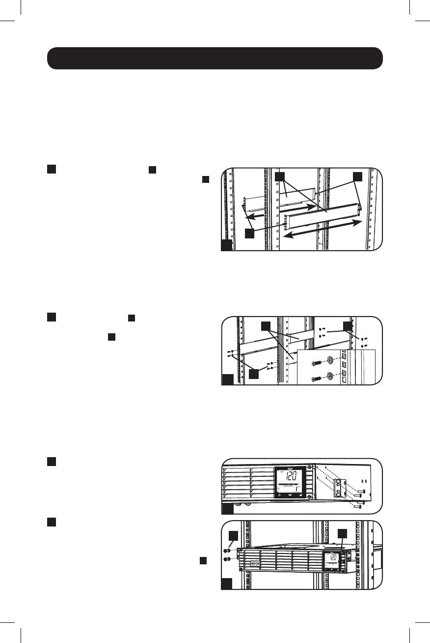
4-Post Mounting
1
The included plastic pegs
A
will temporarily
support the empty rackmount shelves
B
while you install the permanent mounting
hardware.Insertapegnearthecenterofthe
front and rear bracket of each shelf as
shown. (Each front bracket has 6 holes and
each rear bracket has 3 holes.) The pegs will
snap into place.
Afterinstallingthepegs,expandeachshelf
to match the depth of your rack rails. The
pegswillfitthroughthesquareholesinthe
rack rails to support the shelves. Refer to the
rack unit labels to confirm that the shelves
are level in all directions. Note: The support
ledge of each shelf must face inward.
2
Secure the shelves
B
to the mounting rails
permanently using the included screws and
cup washers
C
as shown. Place the cup
washer between the screw and the rack so
that the screw enters the wider opening of
the cup washer first.
Place 4 screws total at the front and 4
screws total at the back.
Tighten all screws before proceeding.
WARNING: Do not attempt to install your
equipment until you have inserted and
tightened the required screws. The
plastic pegs will not support the weight
of your equipment.
3
Attachyourequipment’smountingbracketsto
the forward mounting holes of the cabinet using
the hardware included with your equipment.
The mounting bracket “ears” should face
forward. (Some equipment may have
pre-installedorintegralmountingbrackets.)
4
With theaidof anassistant(if necessary),
lift your equipment and slide it into the
shelves. Attach the equipment mounting
brackets to the forward mounting rails with
user-supplied screws and washers
D
.
Tighten all screws securely.
201205048 93-3149.indb 4 6/19/2012 11:33:31 AM
5
Mounting (Rack) continued
2-Post Mounting/Wall Mounting
2-postmountingrequiresaTrippLite2-PostRackmountInstallationKit(model:2POSTRMKITWM,
sold separately).
WallmountingrequiresaTrippLiteWallMountKit9(2POSTRMKITWM,soldseparately).
Mounting (Tower)
WARNING: When mounting the UPS system in a tower or wall-mount orientation, make sure
the LCD Screen panel is at the top of the UPS, not at the bottom.
Note: To mount the UPS in an upright (tower) position, 2-9USTAND is required (sold separately).
Rotate the LCD Screen panel for easy viewing
whiletheUPSistowermounted.Insertasmall
screwdriver, or other tool, in the slots on either
side of the panel. Pop the panel out, rotate it
and pop the panel back in place.
201205048 93-3149.indb 5 6/19/2012 11:33:32 AM
6
2
3
A
1
Quick Installation
1
Plug the UPS into an outlet on
a dedicated circuit.
Note: After you plug the UPS into a live AC
outlet, the UPS (in “Standby” mode) will
automatically charge its batteries, but will
not supply power to its outlets until it is
turned ON.
2
Plug your equipment into
the UPS.*
* Your UPS is designed to support only electronic
equipment. You will overload the UPS if the total
VA ratings for all the equipment you connect
exceeds the UPS’s Output Capacity. To find your
equipment’s VA ratings, look on its nameplates.
If the equipment is listed in amps, multiply the
number of amps by 120 to determine VA.
(Example: 1 amp × 120 = 120 VA) If you are
unsure if you have overloaded the UPS’s outlets,
see LOAD icon description in LCD Interface
section underBasicOperation.
3
Turn the UPS ON.
Press and hold the button
A
for one
second. The alarm will beep once briefly.
Note: UPS system will function properly upon initial
startup, however, maximum runtime for the unit’s
battery will only be accessible after it has been
charged for 24 hours.
201205048 93-3149.indb 6 6/19/2012 11:33:34 AM
7
USB
RS232
USB
RS232
USB
RS232
1A
1B
2A
4-5
2B
Optional Installation
These connections are optional. Your UPS will function properly without these connections.
1
USB and RS-232 Serial
Communications
UsetheincludedUSBcable(see
1A
)orDB9
serial cable (see
1B
) to connect the
communication port on your computer to the
communicationportofyourUPS.Installon
your computer the Tripp Lite PowerAlert
Software appropriate to your computer’s
operating system.
2
EPO Port Connection
This optional feature is only for those
applications which require connection to a
facility’sEmergencyPowerOff(EPO)circuit.
WhentheUPSisconnectedtothiscircuit,it
enables emergencyshutdownof the UPS’s
inverter.
Usingthe cableprovided, connectthe EPO
portofyourUPS(see
2A
)toauser-supplied
normally closed or normally open switch
according to the circuit diagram (see
2B
).
The EPO port is not a phone line surge
suppressor;donotconnectaphonelineto
this port.
201205048 93-3149.indb 7 6/19/2012 11:33:36 AM
8
3
A
Optional Installation continued
3
External Battery Connection
(Select Models)
Your UPS comes with a robust internal
battery system; external batteries are
needed only to extend runtime. Adding
external batteries will increase recharge time
as well as runtime. This UPS supports
BP24V15RT2U (limit 1), BP24V28-2U (limit
1) and BP24V70-3U (multi-pack).
The illustration (see
3
) shows the location of your UPS’s External Battery Connector
A
where
you will insert the battery pack cable. Complete installation instructions for your battery pack
appear in the battery pack owner’s manual. Make sure that cables are fully inserted into their
connectors. Small sparks may result during battery connection; this is normal.
Do not connect or disconnect battery packs when the UPS is running on battery power.
CAUTION! When an external battery pack is connected, make sure the AC load does not
exceed the nameplate rating. Select models are derated when an external battery pack
is connected. See UPS nameplate label for derating details.
Model Name
Wattage with Internal
Batteries Only
Wattage with External
Batteries Attached
SMART1000RM2U 800W N/A
SMART750RMXL2U 600W 450W
Note:
1. The runtime will automatically recalculate once the External Battery Pack Tool process is complete.
2. If the setup will no longer include external batteries, the UPS can be congured to work without external
batteries via the LCD Screen. See External Battery Settings Control section under Basic Operation for details.
3. If external battery packs are removed, the UPS must be reset to “NO EXTERNAL BATTERY” via the LCD
interface or the External Battery Conguration Program available on the Tripp Lite website. Failure to do so
may result in damage to the internal batteries due to over-charging.
201205048 93-3149.indb 8 6/19/2012 11:33:37 AM
When connecting external batteries to the UPS, go to the Tripp Lite website at www.tripplite.
com/en/support/bpcong/index.cfm to download the External Battery Pack Utility software to
congure your UPS for external battery support.
9
Note: This LCD image is shown
with all icons illuminated. Under
normal conditions, only select
icons will be lit.
Basic Operation
LCD Interface
3-Digit Display:Thisdisplayisgenerallyusedtoshowvaluesforagiven“Display”
or “Control” screen.
“ON/OFF” Button
To turn the UPS ON:AfteryouplugtheUPSintoaliveACoutlet,theUPS(in
“Standby” mode) will automatically charge its batteries, but will not supply
powertoitsoutletsuntilitisturnedON.WiththeUPSpluggedintoaliveAC
walloutlet,pressandholdthe“ON/OFF”buttonforonesecond.*TheUPSwill
beeponcetoindicateONstatus.Releasethebutton.
To cold-start the UPS:Ifutilitypowerisabsent,youcan“cold-start”theUPS
(i.e., turn it on and supply power for a limited time from its batteries) by pressing
andholdingthe“ON/OFF”buttonforonesecond.*TheUPSwillbeeponceto
indicateONstatus.Releasethebutton.
To turn the UPS OFF:WiththeUPSONandreceivingutilitypower,pressand
holdthe“ON/OFF”buttonfor2.5seconds.*TheUPSwillbeeponcetoindicate
OFF status. Then unplug the UPS from the wall outlet. The UPS will be
completely off.
* If the user unintentionally presses the ON/OFF button, the OFF function can be temporarily
canceled by continuing to hold the ON/OFF button until the UPS beeps and then, without
releasing it, momentarily press either the MODE button or the ENTER/MUTE button. Once
both buttons are released, the UPS will remain ON.
“MODE” Button
To enable viewing of power displays and control menu options, tap this button. See
“DisplayPowerConditions”&“ControlMenuOptions”fordetails.
Can be used in conjunction with the ON/OFF button to cancel the “OFF”
function.See“ON/OFFButton”instructionsabove.
CanbeusedinconjunctionwiththeENTER/MUTEbuttontorestoretheLCDto
FactoryMode.See“ControlMenuOptions.”
201205048 93-3149.indb 9 6/19/2012 11:33:38 AM
10
Basic Operation continued
“ENTER/MUTE” Button
To toggle settings options while viewing a control menu option, tap this button.
TheUPSpower failurealarmcan also betemporarily silenced bytappingthis
button. Once silenced, an alarm will automatically re-sound to indicate low
batteryconditionsandcannolongerbesilenced.*
•Can be used in conjunction with the ON/OFF button to cancel the “OFF”
function.See“ON/OFFButton”instructionsabove.
•CanbeusedinconjunctionwiththeENTER/MUTEbuttontorestoretheLCD
toFactoryMode.See“ON/OFFButton”instructions.
Note: Alarm-free silent operation is available by setting the alarm to disable (see
CONTROL MENU OPTIONS / ALARM ENABLE-DISABLE section).
Battery Capacity:Thiswillbeactiveinall“Display”modes,butisnotshownin
“Control” modes.
AC Input: This indicates that the unit is running in Line Mode and supplying AC
powertoequipmentconnectedtotheoutput.
Battery Input:ThiswillflashtoindicatethattheUPSisnotreceivingACinput
andisrunningininvertermode.TheBatteryInputiconisalsousedinconjunction
withtheEVENTSicontoindicateOnBatteryevents.
Replace Battery Icon: In the event that UPS batteries expire and require
replacement, this icon and the warning icon will flash. This icon will also flash
after a failed UPS self-test (see the BASIC OPERATION / CONTROL MENU
OPTIONS/SELF-TESTsectionformoreinformation).
Warning: This will flash to let the user know that there is a warning condition and
immediateactionmustbetaken:
1.For Replace Battery: Replace Battery and Warning icons flash during any
normal“Display”mode.
2.ForOverload:Load,WarningandLoadPercentageiconswillflash,thealarm
willsoundrepeatedlyandtheLCDscreenwillswitchfromtheuser-selected
displaymodetoLoadPercentage.OverloadindicationisavailableinbothAC
and battery modes.
CAUTION! Any overload condition that is not correct by the user
immediately may cause the UPS to shut down and cease supplying output
power in the event of a blackout or brownout.
EVENTS Icon: Displayedinconjunction with the AVRicon and BATTiconsto
indicatethenumberofOnBatteryorAVReventsthathaveoccurred.
Alarm Off:Indicatesthatthealarmisdisabled.
201205048 93-3149.indb 10 6/19/2012 11:33:39 AM
11
Basic Operation continued
Alarm On: Indicatesthatthealarmisenabled.
INPUT Icon: Indicatesthatthe3-digitvaluedisplayedistheInputVoltage.
OUTPUT Icon: Indicatesthatthe3-digitvaluedisplayedistheOutputVoltage.
LOAD Icon:Displayedintwomodes:
1.Displayedinconjunctionwiththe%iconand3-digitvaluetoindicatetheload
percentage.
2.Displayed in conjunction with KWH/Day and 3-digit value to indicate daily
power consumption.
3.BoththeLOADiconandWarningiconwillflashtoindicateanoverload.
BATT Icon: Displayedintwomodes:
1.BATTicon(displayedinconjunctionwith%iconand3-digitvalue)indicates
theBatteryCapacity%.
2.BATTiconisshownwithTESTicontoindicateself-testmodeorcontrolmode.
% Icon:Indicatesunitsof%.
TEST Icon:DisplayedinconjunctionwithBATTicontoindicatethattheUPSis
performingaself-test.
RUNTIME Icon:DisplayedinconjunctionwiththeMINiconand3-digitvalueto
indicate Runtime in minutes.
MIN Icon:Indicatesunitsofminutes.
1.Displayed in conjunction with RUNTIME icon and 3-digit value to indicate
battery runtime in minutes.
2.Displayedinconjunctionwiththe3-digitvalue(reporting“LCD”)toindicatethe
minimum brightness.
VWA Icon: ThisisamultipurposeiconwhichindicatesunitsofVolts,VA,Watts,
orAmps(V,VA,W,orAwillbeshown).
K Icon: DisplayedinconjunctionwiththeWtoindicateKilowatts.Itisalsoused
inconjunctionwiththeWHand/DAYiconstoindicateKilowattHoursperDay.
H and /DAY Icons:Displayedinconjunctionwith“K”and“W”iconstoindicate
KilowattHoursperday(KWH/DAY).
Sensitivity Icon: DisplayedtosettheACinputlinesensitivitysetting.Sensitivity
settingsavailableare100%(Normal=nodelay),50%(halfdelay),and25%
(full delay).
201205048 93-3149.indb 11 6/19/2012 11:33:39 AM
12
SCROLL Icon: When enabled, the display will automatically cycle through each
DISPLAY mode of the LCD once per two-second interval. If a button is pressed
while Scroll Mode is enabled, the scroll function will pause for 10 seconds to allow
the user to manually make menu selections before resuming scroll.
Automatic Voltage Regulation Icon: Indicates that the AC input is either low or
high and that the AVR function is actively boosting or cutting the line. The AVR
icon is also used in conjunction with the EVENTS icon to indicate AVR events.
EXTERNAL BATTERY Icon (Select Models): Displayed only when the EXTERNAL
BATTERY SETTING CONTROL is active.
BATTERY CAPACITY Icon: Used to better describe the battery capacity bar graph.
Basic Operation continued
Display Power Conditions
Use the button to advance through power conditions.
1. Voltage In 2. Voltage Out 3. Estimated Runtime
(in minutes)
4. Load %
5. Load Wattage* 6. KWH/Day** 7. Battery Capacity %
* Load Wattage is displayed in watts up to “999” and then will be displayed in Kilowatts.
** The Kilowatt Hour usage per day reports daily power consumption of equipment connected to the UPS in KWH
in a 24-hour cycle. Press and hold the
button for 4 seconds to reset the accumulator to “0.”
Note: When the UPS is in Battery Mode (power is supplied to the output from the batteries), the BATTERY icon will be
lit in the display instead of the AC INPUT icon. The values displayed are random values used for example reference.
201205048 93-3149.indb 12 6/19/2012 11:33:40 AM
13
Basic Operation continued
Control Menu Options
Enable/Disable Alarm
Tap the buttonrepeatedlytoadvancetotheLCDdisplayfeaturingthe icon. Press the
buttontoselectONorOFFalarmmodesettings.Thelastoptiondisplayedbeforenavigatingaway
from this menu option will be the selected setting.
Note: Disabling the alarm via this control menu option will silence the alarm under all conditions, including low
battery conditions.
LCD Brightness
Tap the buttonrepeatedlytoadvancetotheLCDBrightnessdisplaymarked“LCD.”Pressthe
button to select Medium Backlight (default), High Backlight or Dim Backlight. The last option
displayed before navigating away from this menu option will be the selected setting.
Note: The default brightness is set at medium. Any time a button is pressed, the LCD will engage the high brightness
setting. After 2 minutes of inactivity, the backlight will revert to the selected setting until a button is pressed.
Self-test
Tap the buttonrepeatedlytoadvancetotheTESTBATTdisplay.Pressthe button to initiate
the test. The testwilllastapproximately10seconds as the UPS switches to battery to test the
capacitywithaload.Uponcompletionofthetest,thedisplaywillindicatePASorBAD(passorbad)
for20seconds,andthenreturntothehomescreen.Connectedequipmentcanremainonduring
thetest.DonotunplugyourUPStotestit;thiswillremovesafeelectricalgrounding.
Note: If the self-test result is BAD, it may be due to the batteries not being charged for 24 hours. Fully charge the
batteries and repeat the self-test. Please refer to the note under Step 3 on Page 6.
Scroll Control
This setting is normally set to “OFF.” Setting it to “ON” allows the user to select the option to
automaticallyscrolleachoperatingconditionoftheUPS(suchasInputVoltage,OutputVoltageand
Runtime) automatically.
Tap the button repeatedly to advance to the Scroll display as shown above.
Press the button to advance to the next available option. The last option displayed, before
navigating away from this menu option, will be the selected setting.
Note:
1. Each condition is displayed in 2-second intervals.
2. If a button is pressed while Scroll Mode is enabled, the scroll function will pause for 10 seconds to allow the
user to manually make menu selections.
201205048 93-3149.indb 13 6/19/2012 11:33:40 AM
14
ON Battery Events
ThisfeatureallowstheusertoviewthenumberoftimestheUPShasexperiencedanONBattery
Event. To reset the counter to “0,” press and hold the button.
Basic Operation continued
Tap the buttonrepeatedlytoadvancetotheONBatteryEventsdisplay,asshownabove.
Note: The value displayed is a random value used for example reference.
AVR Events
Thisfeature allowstheusertoview thenumberoftimesthe UPShasexperiencedanAutomatic
VoltageRegulationEvent.Toresetthecounterto“0,”pressandholdthe button.
Tap the buttonrepeatedlytoadvancetotheAVRdisplay,asshownabove.
Note: The value displayed is a random value used for example reference.
Power Sensitivity
Thissettingisnormallysetto100%,whichenablestheUPStoprotectagainstwaveformdistortions
initsACinput.Whensuchdistortionoccurs,theUPSwillnormallyswitchtoprovidingpuresinewave
powerfromitsbatteryreservesforaslongasthedistortionispresent.Insomeareaswithpoorutility
powerorwheretheUPS’sinputpowercomesfromabackupgenerator,frequentbrownoutsand/or
chronicwaveformdistortioncouldcausetheUPStoswitchtobatterytoooften,drainingitsbattery
reserves. You may be able to reduce how often your UPS switches to battery due to waveform
distortionorbrownoutsbyexperimentingwithdifferentsettings.Asthesettingisreduced,theUPS
becomes more tolerant of variations in its input power’s AC waveform.
Note: When experimenting with different settings, operate connected equipment in a safe test mode so that the
effect on the equipment of any waveform distortions in the UPS’s output can be evaluated without disrupting critical
operations. The experiment should last long enough to assure that all expected line conditions are encountered.
201205048 93-3149.indb 14 6/19/2012 11:33:41 AM
15
YES
Basic Operation continued
Tap the button repeatedly to advance to Sensitivity display, as shown on the previous page.
Press the button to advance through the options. The last option displayed, before navigating
away from this menu option, will be the selected setting.
External Battery Setting Control (Select Models)
ThiscontrolmenuoptiononlyappearswhentheUPSisconfiguredusingtheExternalBatteryUtility
softwareandisreporting“YES”intheExternalBatteryLCDControlScreen.Thissettingisnormally
setto“YES.”TheonlyavailableLCDinterfaceconfigurationoptionistochangethesettingfrom“YES”
to“NO”externalbatteries.
Note: See the Optional Installation section for information on configuring the UPS for external battery operation
using the External Battery Utility software.
Tap the buttonrepeatedlytoadvancetotheExternalBatterydisplay,asshownabove.
TosettheUPSto“NO”ExternalBattery,pressandholdthe buttonfor3.5seconds.
Note: The Battery Runtime calculation is based on this setting. The runtime will automatically recalculate once the
external battery setting is configured for “NO” external batteries.
Factory Mode Reset
TheLCDsettingscanberestoredtoFactoryModebyholdingtheMODEandENTER/MUTEbuttons
simultaneouslyfor5secondswhileinanydisplaymode.
CAUTION: This action cannot be undone. The user must reconfigure the UPS for external
batteries if the UPS’s setup includes external batteries.
201205048 93-3149.indb 15 6/19/2012 11:33:41 AM
16
15A 120V
NEMA 5-15R
Basic Operation continued
Other UPS Features (Rear Panel)
AC Outlets: All models include NEMA 5-15R outlets. These outlets provide your
connected equipment with AC line power during normal operation and battery
power during blackouts and brownouts. The UPS protects equipment connected
to these outlets against damaging surges and line noise. If you have a serial or
USB connection to your UPS, you can remotely reboot connected equipment by
turning the outlets OFF and ON using Tripp Lite’s PowerAlert Software. The outlets
are divided into one or more load banks (labelled “LOAD 1,” etc.) which may be
remotely switched OFF and ON without interrupting power to equipment
connected to the other outlets. Outlets labelled “UNSWITCHED” may not be
remotely switched o.
Communications Ports (USB or RS-232): These ports connect your UPS to any
workstation or server. Use with Tripp Lite’s PowerAlert Software and included
cables to enable your computer to automatically save open les and shut down
equipment during a blackout. Also use PowerAlert Software to monitor a wide
variety of AC line power and
UPS operating conditions. Consult your PowerAlert
Software manual or contact Tripp Lite Customer Support for more information.
See “USB and RS-232 Serial Communications” in the “Optional Installation”
section for installation instructions.
EPO (Emergency Power O) Port: Your UPS features a EPO port that may be
used to connect the UPS to a contact closure switch to enable emergency inverter
shutdown. See Optional Installation.
Accessory Slot: Remove the small cover panel from this slot to install optional
accessories to remotely monitor and control your UPS. Refer to your accessory’s
manual for installation instructions. Contact Tripp Lite Customer Support at
(773) 869-1234 for more information, including a list of available SNMP, network
management and connectivity products.
External Battery Connector (optional on select models): Use to connect
Tripp Lite external battery packs for additional runtime. Refer to instructions
available with the battery pack for complete connection information and safety
warnings. Visit www.tripplite.com/support/battery/index.cfm to locate the supported
battery type(s) for your UPS.
Input Breaker: Your UPS features one breaker that protects your UPS. If
breaker trips, remove some of the load on the circuit, then reset it by pressing
the breaker switch in.
Ground Screw: Use
this to connect any equipment that requires a chassis ground.
201205048 93-3149.indb 16 6/19/2012 11:33:42 AM
the
17
Storage and Service
Storage
BeforestoringyourUPS,turnitcompletelyOFF:withtheUPSONandreceivingutilitypower,press
andholdthe“ON/OFF”buttonfortwoseconds(analarmwillbeeponcebrieflyaftertheintervalhas
passed);then,unplugtheUPSfromthewalloutlet.IfyoustoreyourUPSforanextendedperiodof
time,rechargetheUPSbatteriesonceeverythreemonths:plugtheUPSintoawalloutlet;allowit
tochargefor12hours;andthenunplugitandplaceitbackinstorage.IfyouleaveyourUPSbatteries
dischargedforanextendedperiodoftime,theywillsufferapermanentlossofcapacity.
Service
AvarietyofExtendedWarrantyandOn-SiteServiceProgramsarealsoavailablefromTrippLite.For
more information on service, visit www.tripplite.com/support. Before returning your product for
service,followthesesteps:
1. Review the installation and operation procedures in this manual to insure that the service
problem does not originate from a misreading of the instructions.
2. If the problem continues, do not contact or return the product to the dealer. Instead, visit
www.tripplite.com/support.
3. Iftheproblemrequiresservice,visitwww.tripplite.com/supportandclicktheProductReturnslink.
FromhereyoucanrequestaReturnedMaterialAuthorization(RMA)number,whichisrequired
for service. This simple online form will ask for your unit’s model and serial numbers, along with
other general purchaser information. The RMA number, along with shipping instructions, will be
e-mailedtoyou.Anydamages(direct,indirect,specialorconsequential)totheproductincurred
during shipment to Tripp Lite or an authorized Tripp Lite service center is not covered under
warranty. Products shipped to Tripp Lite or an authorized Tripp Lite service center must have
transportationchargesprepaid. Mark the RMAnumberon the outsideofthe package. Ifthe
product is within its warranty period, enclose a copy of your sales receipt. Return the product for
serviceusinganinsuredcarriertotheaddressgiventoyouwhenyourequesttheRMA.
201205048 93-3149.indb 17 6/19/2012 11:33:42 AM
18
1
3
2
4 x screws
4 x screws
4
Battery Replacement
Undernormalconditions,theoriginalbatteriesinyourUPSwilllastmanyyears.SeeSafetysection
beforereplacingbatteries.Thebatteries aredesignedforhot-swapreplacement (i.e.,leavingthe
UPSinONmode),butsomequalifiedservicepersonnelmaywishtoputtheUPSintheOFFmode
anddisconnectequipmentbeforeproceeding.
Note: Refer to the label on the battery retention plate for the R.B.C. part number.
SMART750RMXL2U and SMART1000RM2U Battery (RBC24VLCD)
Replacement Procedure
2
Remove Battery Retention Plate
3
Disconnect Batteries
4
Remove/Recycle Batteries
1
Remove Front Panel
201205048 93-3149.indb 18 6/19/2012 11:33:45 AM
19
7
8
4 x screws
4 x screws
5
6
Battery Replacement
5
Add New Batteries
6
Connect Batteries
7
Replace Battery Retention Plate
8
Replace Front Panel
201205048 93-3149.indb 19 6/19/2012 11:33:48 AM
20
FCC Notice, Class B
This device complies with part 15 of the FCC Rules. Operation is subject to the following two conditions: (1) This
device may not cause harmful interference; and (2) this device must accept any interference received, including
interference that may cause undesired operation.
Note: This equipment has been tested and found to comply with the limits for a Class B digital device, pursuant
to part 15 of the FCC Rules. These limits are designed to provide reasonable protection against harmful
interference when the equipment is operated in a commercial environmen
t. This equipment generates, uses, and
can radiate radio frequency energy, and, if not installed and used in accordance with the instruction manual, may
cause harmful interference to radio communications. Operation of this equipment in a residential area is likely to
cause harmful interference in which case the user will be required to correct the interference at his own expense.
The user must use shielded cables and connectors with this equipment. Any changes or modications to this
equipment not expressly approved by Tripp Lite could void the user’s authority to operate this equipment.
Regulatory Compliance Identication Numbers
For the purpose of regulatory compliance certications and
identication, your Tripp Lite product has been assigned a
unique series number. The series number can be found on the
product nameplate label, along with all required approval
markings and information. When requesting compliance
information for this product, always refer to the series number.
The series number should not be confused with the marking
name or model number of the product.
Tripp Lite has a policy of continuous improvement. Product specications are subject to change without notice.
Note on Labeling
Two symbols are used on the label.
V~ : AC Voltage
V
: DC Voltage
Warranty Registration
Visit www.tripplite.com/warranty today to register the warranty for your new Tripp Lite product.
You’ll be automatically entered into a drawing for a chance to win a FREE Tripp Lite product!*
* No purchase necessary. Void where prohibited. Some restrictions apply. See Web site for details.
1111 W. 35th Street, Chicago, IL 60609 USA
www.tripplite.com/support
201205048 933149-EN
201205048 93-3149.indb 20 6/19/2012 11:33:48 AM
  • Page 1 1
  • Page 2 2
  • Page 3 3
  • Page 4 4
  • Page 5 5
  • Page 6 6
  • Page 7 7
  • Page 8 8
  • Page 9 9
  • Page 10 10
  • Page 11 11
  • Page 12 12
  • Page 13 13
  • Page 14 14
  • Page 15 15
  • Page 16 16
  • Page 17 17
  • Page 18 18
  • Page 19 19
  • Page 20 20
  • Page 21 21
  • Page 22 22
  • Page 23 23
  • Page 24 24
  • Page 25 25
  • Page 26 26
  • Page 27 27
  • Page 28 28
  • Page 29 29
  • Page 30 30
  • Page 31 31
  • Page 32 32
  • Page 33 33
  • Page 34 34
  • Page 35 35
  • Page 36 36
  • Page 37 37
  • Page 38 38
  • Page 39 39
  • Page 40 40
  • Page 41 41
  • Page 42 42
  • Page 43 43
  • Page 44 44
  • Page 45 45
  • Page 46 46
  • Page 47 47
  • Page 48 48
  • Page 49 49
  • Page 50 50
  • Page 51 51
  • Page 52 52
  • Page 53 53
  • Page 54 54
  • Page 55 55
  • Page 56 56
  • Page 57 57
  • Page 58 58
  • Page 59 59
  • Page 60 60

Tripp Lite SmartPro SMX3000XLRT2UA User manual

Category
Uninterruptible power supplies (UPSs)
Type
User manual

Ask a question and I''ll find the answer in the document

Finding information in a document is now easier with AI